Table of Contents
Advertisement
Available languages
Available languages
Advertisement
Chapters
Table of Contents

Related Manuals for Eurotherm 3216i


Summary of Contents for Eurotherm 3216i
- Page 1 E U ROT H E R M User Guide Manuel Utilisateur Bedienungsanleitung...
- Page 2 This booklet includes: User Guide (HA029005 Issue 2) Manuel Utilisateur (HA029005FRA Indice 1) Bedienungsanleitung (HA029005GER Ausgabe 1)
-
Page 3: Table Of Contents
3200i Series Process Indicators and Alarm Units Applies to Model numbers 3216i, 32h8i and 3204i Contents What Instrument Do I Have?..................4 Unpacking Your Indicator ........................5 Dimensions Front Views ........................5 Dimensions – Side and Top Views ....................... 6 Step 1: Installation ..........................7 1.4.1... - Page 4 Indicator Power Supply ........................16 Example Wiring Diagram ........................16 Digital Communications (Optional) ....................17 2.10 Additional Connections for 3216i ...................... 18 2.10.1 Input/Output 1 & Output 2 ............................... 18 Safety and EMC Information ..................19 Installation Safety Requirements....................... 20 Switch On ........................
- Page 5 Issue 2 of this manual applies to firmware version 1.03 and contains the following changes:- Load cell and shunt calibration explained in more detail. Separate ‘Set 2’ codes for 32h8i/3204i and 3216i for clarity Add note on sensor break for transducers Add note on FM DIN3440 indicators.
-
Page 6: What Instrument Do I Have
4. Changeover use the indicator. For features not covered in this relay User Guide, a detailed Engineering Manual, Part No and Transmitter HA029006, and other related handbooks can be downloaded from www.eurotherm.co.uk. 32h8i/SG Strain gauge As 32h8i 3204i As 3216i As 32h8i Part number HA029005. -
Page 7: 1.1 Unpacking Your Indicator
Model 3216i 1.1 Unpacking Your Indicator The following items are included in the box: Latching • Indicator mounted in its sleeve 48mm ears (1.89in) • Two panel retaining clips • AN IP65 sealing gasket mounted on the sleeve 48mm •... -
Page 8: 1.3 Dimensions - Side And Top Views
1.3 Dimensions – Side and Top Views Side View –1/8 DIN & 1/4 DIN Side View –1/16 DIN 48mm (1.89in) 96mm (3.78in) 90mm (3.54in) Top View – 1/16 & 1/8 DIN 48mm (1.89in) 90mm (3.54in) Latching ears 90mm (3.54in) Panel retaining clip IP65 Sealing Gasket d = Fascia depth 1.25mm (0.5in) Part number HA029005. -
Page 9: Step 1: Installation
- 0.0 + 0.6 The indicator can be mounted on a panel up to Model Model 32h8i 15mm thick 3216i 1.77 inch -0.00, +0.02 To ensure IP65 and NEMA 4 front sealing against dust and water, mount on a non-textured surface. -
Page 10: Recommended Minimum Spacing Of Indicators
Recommended minimum spacing of 1.4.4 To Remove the Indicator from its 1.4.3 indicators. Sleeve The indicator can be unplugged from its sleeve by easing the latching ears outwards and pulling it Applies to all Model sizes forward out of the sleeve. When plugging it back into its sleeve, ensure that the latching ears click 10mm (0.4 inch) back into place to maintain the IP65 sealing. -
Page 11: 1.5 Ordering Code
(3216i only) 11. Warranty Standard Unit Digital input A (not 32h8i/SG, Standard XXXXX FM Alarm Unit optional in 3216i) Extended WL005 DIN 3440 alarm unit RS232 & Digital input A (includes Dig In A except Strain Gauge Input 32h8i only 12. -
Page 12: Step 2: Wiring
Logic (SSR drive) output Relay output Contact input mA analogue output 2.1 Terminal Layout 3216i Indicator Ensure that you have the correct supply for your indicator. Check order code of the indicator supplied Digital input A Input/Output 1 10V Potential divider... -
Page 13: 2.2 Terminal Layout 32H8I Indicator
2.2 Terminal Layout 32h8i Indicator Ensure that you have the correct supply for your indicator. Check order code of the indicator supplied Line Supply 100 to 240Vac 50/60Hz OP3 DC Output 1 (OP1) Transmitter Retrans Dig in B Low Voltage Supply 24Vac/dc Changeover Supply V/mA... -
Page 14: 2.3 Terminal Layout 3204I Indicators
2.3 Terminal Layout 3204i Indicators Ensure that you have the correct supply for your indicator. Check order code of the indicator supplied Output 1 (OP1) AA Relay (OP4) Digital A(+) Communications Digital Input B RS232 or RS485 B(-) 3204i Indicator DC Retrans (OP3) mA only Digital... -
Page 15: 2.4 Wire Sizes
0-10V SUB21/IV10, is available preferably shielded. 806Ω for 3216i and 3204i. - Negative • It is not recommended to Sensor break alarm does not operate when this adaptor connect two or more instruments to one thermocouple. -
Page 16: Outputs - 1/8 And 1/4 Din Indicators
Outputs - 1/8 and 1/4 DIN * General Notes about Relays and Inductive Loads Indicators High voltage transients may occur when switching 32h8i and 3204i indicators are supplied as standard inductive loads such as some contactors or solenoid with two changeover relay outputs. valves. -
Page 17: Output 3 Retransmission (Output 2 3216I)
Switching: 12Vdc at 40mA max • • Output functions: PV retransmission. Contact open > 500Ω. Contact closed < 200Ω • • Output 2 non-isolated on 3216i Input functions: Please refer to the list in the quick codes. 2.6.3 Transmitter Supply 2.6.5 Transducer Supply A fixed 24Vdc supply is available to power an external transducer (not 3216i). -
Page 18: Indicator Power Supply
Indicator Power Supply Example Wiring Diagram This shows 32h8i connected to a strain gauge bridge. Before connecting the indicator to the power line, make sure that the line voltage corresponds to the description on the identification label. Fuse 3D 3C LB 2B Use copper conductors only. -
Page 19: Digital Communications (Optional)
Digital Communications (Optional) RS485 Connections Digital communications uses the Modbus protocol. The interface may be ordered as RS232 or RS485 (2- wire). * RS232/RS485 2-wire • Isolated 240Vac CATII. communications converter RS232 Connections eg Type KD485 Rx Tx 220Ω termination Screen resistor on last instrument in the line... -
Page 20: Additional Connections For 3216I
2.10 Additional Connections for 3216i DC Output Connections for the 3216i indicator are similar to the • Not isolated from the sensor input OP1/2 3216 controller. • 2.10.1 Input/Output 1 & Output 2 Software configurable: 0-20mA or 4-20mA. I/O1 may be configured as input or output. -
Page 21: Safety And Emc Information
3. Safety and EMC Information GENERAL This indicator is intended for industrial temperature The information contained in this manual is subject to change without notice. While every effort has been and process applications when it will meet the requirements of the European Directives on Safety and made to ensure the accuracy of the information, your supplier shall not be held liable for errors contained EMC. -
Page 22: Installation Safety Requirements
Caution: Charged capacitors may be used to clean other exterior surfaces of the product. Before removing an instrument from its sleeve, Installation Safety Requirements disconnect the supply and wait at least two minutes to allow capacitors to discharge. It may be convenient to Safety Symbols partially withdraw the instrument from the sleeve, then pause before completing the removal. - Page 23 Caution: Live sensors operator and marked as the disconnecting device for the instrument. The indicator is designed to operate if the temperature sensor is connected directly to an electrical heating Overcurrent protection element. However, you must ensure that service The power supply to the system should be fused personnel do not touch connections to these inputs appropriately to protect the cabling to the units.
- Page 24 Over-temperature protection in conditions of conductive pollution, fit an air filter to the air intake of the cabinet. Where condensation is When designing any control system it is essential to likely, for example at low temperatures, include a consider what will happen if any part of the system thermostatically controlled heater in the cabinet.
- Page 25 • For general guidance refer to Eurotherm Controls EMC Installation Guide, HA025464. • When using relay outputs it may be necessary to fit a filter suitable for suppressing the emissions.
-
Page 26: Switch On
4. Switch On ▲ ▼ Press to change the flashing New Indicator character to the required code shown in the quick code tables –see next page. Note: An If the indicator is new and has not previously been indicates that the option is not fitted. configured it will start up showing the ‘Quick Start’... - Page 27 Kg/cm parameters mmWG 0-80mV inWG 0-20mA mmHG 4-20mA Up to 2 decimal places on 3216i and 3204i Torr Linear 32h8i only Up to 4 decimal places on 32h8i 0-10Vdc 1-5Vdc Colour change on top part of display only 2-10Vdc 0-5Vdc Part number HA029005.
-
Page 28: Part Number Ha
SET 2 32h8i & 3204i H 3 L W V OP4 (AA Relay) Digital input A and B Unconfigured Unconfigured Unconfigured Unconfigured Relay Output Analogue Output (Dig in A not available on 32h8i/SG) Alarm 1 PV Retransmission Alarm 4 Alarm High alarm 4-20mA High alarm... - Page 29 SET 2 - 3216i h L g w x IO1 and OP2 OP4 (AA Relay) Digital input A Relay or Logic Output Analogue Output Unconfigured Unconfigured Alarm 1 PV Retransmission Alarm 4 High alarm 4-20mA High alarm Alarm Low alarm...
-
Page 30: To Re-Enter Quick Code Mode
If the Quick Codes do not appear during start up, This may be downloaded from this means that the indicator has been configured in www.eurotherm.co.uk. a deeper level of access, see previous note. The quick codes may then not be valid and are therefore not shown. -
Page 31: Front Panel Layout
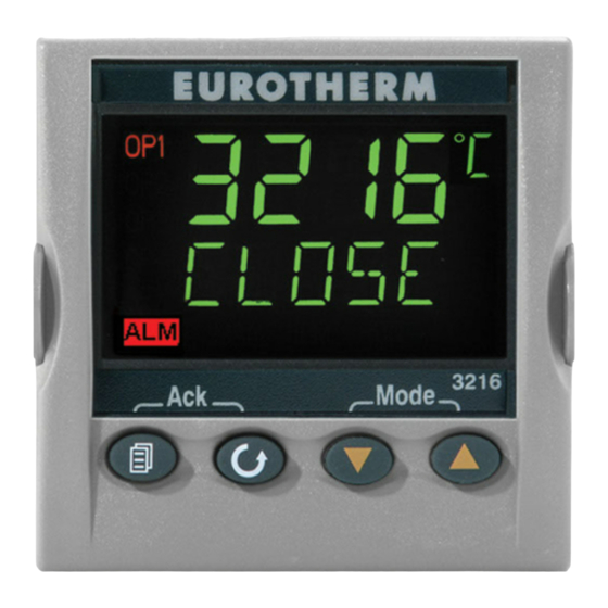
1, and a low alarm is configured to Lit when output 1 is ON operate output 4, the scrolling messages ‘ALARM This appears in 3216i only and is lit 1 HIGH’ and ‘ALARM 4 LOW’ are shown when output 2 is ON together with the beacons ‘ALM’, ‘OP1’... -
Page 32: Alarm Indication
Alarm Indication 4.3.3 Sensor Break Indication 4.3.1 Up to four alarms can be configured. If any alarm An alarm condition (S.br) is indicated if the sensor occurs, the red ALM beacon will flash. A scrolling or the wiring between sensor and indicator becomes text message will describe the source of the alarm, for open circuit. -
Page 33: Operator Parameters In Level 1
Operator Parameters in Level 1 The value of the parameter is shown in the upper Operator level 1 is designed for day to day operation display. In level 1 the value is read only. of the indicator and access to these parameters is not protected by a pass code. -
Page 34: Tare Correction
4.4.1 Tare Correction Alternatively, a digital input may have been set by selecting T in the quick codes (section 4.1) to provide Tare correction can be made in Operator Level 1. It is this function via an external source such as a switch used, for example, when it is required to weigh the or pushbutton. -
Page 35: Operator Level 2
5. Operator Level 2 ▲ ▼ Press to enter the Level 2 provides access to additional parameters. It is pass code. Default = ‘2’ protected by a security code. If an incorrect code is entered the indicator To Enter Level 2 reverts to Level 1. -
Page 36: Level 2 Parameters
Level 2 Parameters Backscroll is achieved when you are in this list by As in Level 1, press to step through the list of parameters. The mnemonic of the parameter is ▲ repeatedly pressing while holding down shown in the message centre. After five seconds a scrolling text description of the parameter appears. - Page 37 Mnemonic Scrolling Display and description Range STRAIN GAUGE CALIBRATION TYPE Select the calibration for the Strain gauge SG.TYP SHnt type of sensor in use. bridge Comparison ComP Load cell CELL SHUNT CALIBRATION To set the high calibration point for a bridge OFF or 40.0 to 100.0% SHUNT type strain gauge or pressure transducer.
- Page 38 Mnemonic Scrolling Display and description Range CUSTOMER ID Customised instrument identification number 0 to 9999 CURRENT RECIPE NUMBER The recipe currently in use. No recipe REC.NO none See also section 5.4 1 to 5 selected 1 - 5 Fail is shown if no FaiL recipe is saved STORE...
- Page 39 Mnemonic Scrolling Display and description Range DISPLAY UNITS The display units are shown in the top right hand UNITS corner of the display in normal operation. Units available are:- Kelvin none No units displayed Perc Percentage Pascals * Mpascals * Kpascals * Bar * mbar...
-
Page 40: Strain Gauge Calibration
Strain Gauge Calibration 5.3.1 To configure the different modes:- The 32h8i/SG indicator is designed to operate with symmetrical bridge type strain gauges, nominally In operator level 2:- 350Ω in each arm. It is generally necessary to calibrate the instrument to the transducer in use. This Press until SG.TYP is shown in the lower can be done in Operator Level 2 using any one of... -
Page 41: Load Cell Calibration
5.3.2 Load Cell Calibration In level 2, press until LO.CAL is shown in Connect a load cell as shown below:- the lower display Remove all weight from the load cell and press Fuse 3D 3C LB 2B ▲ ▼ to select yes Txdcr The indicator will show busy as it calibrates... -
Page 42: Comparison Calibration
5.3.3 Comparison Calibration 5.3.4 Shunt Calibration Comparison calibration is most appropriate when A bridge type strain gauge is connected as shown. calibrating the indicator against a second reference Depending on the type of gauge, R may be device. included internally or supplied as a separate item. The load cell is connected as shown in the previous example. -
Page 43: Manual Calibration
5.3.5 Manual Calibration 5.3.6 Automatic Calibration Remove all pressure from the transducer to Remove all pressure from the transducer to establish a zero reference establish a zero reference In operator level 2, press until SHUNT is In operator level 2, press until AUT.SG is shown in the lower display. -
Page 44: Calibration Using A Digital Input
5.3.7 Calibration Using a Digital Input A digital input may have been set by selecting ‘Z’ in the quick codes (section 4.1) to allow the transducer to be calibrated automatically via an external source such as a switch or pushbutton. In this case pressing the button will have the same effect as selecting yes in 3 above. -
Page 45: Recipes
Recipes 5.4.2 To Load a Recipe It is possible to store operating values in up to five In the list of parameters, press to select different recipes by taking a snapshot of the current rec.no settings and storing these in a recipe number. Select a recipe number from 1 to 5 in which the Examples, of typical operating parameters may be required settings have been stored. -
Page 46: Fm And Din 3440 Alarm Units
FM and DIN 3440 Alarm Units Further details on latching and inverted alarms can be found in the Engineering Manual Part No. 3200 indicators supplied to Function code FM are FM HA029006. approved. 3200 indicators supplied to Function code DN are approved to DIN3440. - Page 47 E U ROT H E R M Manuel Utilisateur...
- Page 49 Indicateurs de procédé et unités d'alarme de la série 3200i S'applique aux modèles 3216i, 32h8i et 3204i Table des matières Présentation générale de l'appareil..............4 Déballer l'indicateur ......................5 Dimensions - Vues de face .....................5 Dimensions – Vues de côté et de dessus ................6 Etape 1 : installation ......................7...
- Page 50 2.6.1 Sortie 1 & Sortie 4 (relais AA) ..........................14 2.6.2 Sortie 3 Retransmission (Sortie 2 pour le 3216i) ..................... 15 2.6.3 Alimentation capteur/transmetteur........................15 2.6.4 Entrées logiques A et B............................15 2.6.5 Alimentation d'un transducteur..........................15 Alimentation électrique de l'indicateur................16 Exemple de schéma de câblage ...................
- Page 51 Niveau opérateur 2 ..................34 Pour passer en niveau 2 .......................34 5.1.1 Pour revenir en niveau 1 ............................34 Paramètres de niveau 2......................35 Calibration de la jauge de contrainte ..................40 5.3.1 Calibration de la cellule de mesure ........................41 5.3.2 Calibration par comparaison..........................42 5.3.3 Calibration par shunt..............................42 5.3.4...
-
Page 52: Présentation Générale De L'appareil
Manuel de configuration détaillé 2 Logique relais inverseur (référence HA029006) et d'autres manuels associés 32h8i/SG 1/8 DIN Jauge de Comme 32h8i sur le site www.eurotherm.co.uk. contrainte 3204i 1/4 DIN Comme Comme 32h8i 3216i Référence HA029005FRA Indice 1.0 Septembre 05. -
Page 53: Déballer L'indicateur
Modèle 3216i Déballer l'indicateur La boîte contient les éléments suivants : • Indicateur monté dans son boîtier 48 mm Clips de • Deux clips de fixation sur panneau verrouillage • Un joint d'étanchéité IP65 monté sur le boîtier 48 mm •... -
Page 54: Dimensions - Vues De Côté Et De Dessus
Dimensions – Vues de côté et de dessus Vue de côté –1/8 DIN & 1/4 DIN Vue de côté –1/16 DIN 48 mm 96 mm 90 mm Vue de dessus – 1/16 & 1/8 48 mm 90 mm Clips de verrouillage 90 mm Clip de fixation Joint d'étanchéité... -
Page 55: Etape 1 : Installation
45 mm Modèle 32h8i - 0,0 + 0,6 3216i Prière de lire les consignes de sécurité de la section 3 avant toute utilisation. Le manuel EMC portant la 92 mm - 0,0 + 0,8 référence HA025464 contient de plus amples 45 mm informations sur l'installation. -
Page 56: Espacement Minimal Entre Indicateurs
Espacement minimal entre 1.4.4 Pour retirer l'indicateur de son 1.4.3 indicateurs. boîtier L'indicateur peut être retiré de son boîtier par traction vers l'avant après déblocage des pattes Applicable à tous les modèles d'ancrage. Au remontage dans le boîtier, s'assurer que les pattes d'ancrage sont bien engagées afin que 10 mm l'indice de protection IP65 soit maintenu. -
Page 57: Code De Commande
32h8i Dimension 1/8 DIN (horizontal) 1-10 V continu 6. Options 3204i Dimension 1/4 DIN Résistance de shunt Non équipé (3216i mA (2,49 Ω) uniquement) 2. Fonction Entrée logique A (pas sur le 11. Garantie Appareil standard 32h8i/SG, en option sur le... -
Page 58: Etape 2 : Câblage
Légende des symboles utilisés dans les schémas électriques Sortie logique (SSR) Sortie relais Entrée contact Sortie analogique mA Bornier de raccordement Indicateur 3216i Vérifier la compatibilité de l'indicateur avec l'alimentation réseau. Vérifier avec le code de commande de l'indicateur livré Entrée logique A Module diviseur de tension 10 V Entrée/sortie 1... -
Page 59: Bornier De Raccordement - Indicateur 32H8I
Bornier de raccordement - Indicateur 32h8i Vérifier la compatibilité de l'indicateur avec l'alimentation réseau. Vérifier avec le code de commande de l'indicateur livré Alimentation réseau Alimentation 100 à 240 V alternatif 50/60Hz Entrée OP3 DC Sortie 1 (OP1) logique B Retrans Relais transmetteur... -
Page 60: Bornier De Raccordement - Indicateurs 3204I
Bornier de raccordement - Indicateurs 3204i Vérifier la compatibilité de l'indicateur avec l'alimentation réseau. Vérifier avec le code de commande de l'indicateur livré Sortie 1 (OP1) Relais AA (OP4) Communications A(+) numériques Entrée logique B B(-) RS232 ou RS485 Indicateur 3204i Retrans DC (OP3) mA uniquement Entrée... -
Page 61: Section Des Fils
Entrée thermocouple Entrées tension linéaires Un diviseur de tension Positif externe est nécessaire Entrée Négatif pour les modèles 3216i et 0-10 V 3204i, il porte la • Utiliser un câble de compensation approprié, de référence SUB21/IV10. préférence blindé. Référence HA029005FRA Indice 1.0... -
Page 62: Sorties - Indicateurs 1/8 Et 1/4 Din
Sorties - Indicateurs 1/8 et 1/4 DIN ces transitoires peuvent occasionner des perturbations susceptibles de nuire au bon fonctionnement de Les indicateurs 32h8i et 3204i sont livrés de manière l'instrument. standard avec deux sorties relais inverseur. Pour ce type de charge, il est recommandé de protéger le contact travail du relais de commutation avec un 2.6.1 Sortie 1 &... -
Page 63: Sortie 3 Retransmission (Sortie 2 Pour Le 3216I)
Contact ouvert > 500 Ω. Contact fermé < 200 Ω • Fonctions de la sortie : retransmission de PV. • Fonctions de l'entrée : se reporter à la liste dans • Sortie 2 non isolée sur le modèle 3216i les codes rapides. 2.6.3 Alimentation capteur/transmetteur 2.6.5 Alimentation d'un transducteur Il existe une source 24 V continu pour l'alimentation Le modèle 32h8i/SG comporte une alimentation 10 V... -
Page 64: Alimentation Électrique De L'indicateur
Alimentation électrique de Exemple de schéma de câblage l'indicateur Cet exemple illustre un modèle 32h8i relié à un pont de jauge. Avant de connecter l'indicateur au réseau électrique, vérifier que la tension de ligne correspond à la description figurant sur Fusible l'étiquette d'identification. -
Page 65: Communications Numériques (En Option)
Communications numériques (en option) Connexions RS485 Les communications numériques utilisent le protocole Modbus. L'interface peut être commandée au choix au * Convertisseur de standard RS232 ou RS485 (2 fils). communications bifilaire • Isolée 240 V ca CATII. RS232/RS485, par exemple Connexions RS232 de type KD485 Rx Tx... -
Page 66: Connexions Supplémentaires Pour Le 3216I
3216i • Sortie Etat non actif (OFF) : <300 mV, <100 µA Les connexions pour l'indicateur 3216i sont identiques à celles du régulateur 3216. • Fonctions de la sortie : alarme ou événement 2.10.1 Entrée/Sortie 1 & Sortie 2 Sortie DC L'E/S1 peut être configurée comme entrée ou comme... -
Page 67: Informations Relatives À La Sécurité Et À La Compatibilité Électromagnétique
3. Informations relatives à la l'application d'un dossier de construction technique. Cet appareil répond aux exigences générales sécurité et à la compatibilité d'environnement industriel décrites dans la norme EN électromagnétique 61326. Pour plus d'informations sur la conformité du produit, consulter le dossier de construction technique. Cet indicateur est destiné... -
Page 68: Exigences De Sécurité De L'installation
Révision et réparation éviter ce phénomène, avant d'utiliser le régulateur débranché, il faut se relier à la terre. Cet indicateur ne comporte aucune pièce sur laquelle Nettoyage l'utilisateur peut intervenir. Prendre contact avec le fournisseur pour toute réparation. Ne pas nettoyer les étiquettes avec de l'eau ou des produits à... - Page 69 Personnel pas relier l'alimentation alternative à l'entrée basse tension de la sonde et aux entrées et sorties bas niveau. L'installation doit uniquement être effectuée par du Utiliser exclusivement des conducteurs en cuivre pour personnel qualifié. les connexions (sauf pour les entrées thermocouple) et veiller à...
- Page 70 Tension nominale Ce produit a été conçu pour satisfaire aux exigences de la norme BSEN61010, catégorie d'installation II, degré de La tension maximale appliquée entre les bornes pollution 2. Ces exigences sont définies de la manière suivantes ne doit pas dépasser 240 V alternatif : suivante : •...
- Page 71 : • un défaut du régulateur dont la sortie de • Pour les indications générales, consulter le guide chauffage fonctionnerait en permanence d'installation CEM HA025464 d'Eurotherm • Automation. une vanne ou un contacteur externe restant en position chauffage •...
- Page 72 applications types, nous recommandons les filtres Schaffner FN321 ou FN612. • Si l'unité doit être utilisée avec un matériel sur table, branché sur une prise d'alimentation standard, la conformité aux normes d'émissions commerciales et de l'industrie légère doit être respectée. Dans ce cas, afin de satisfaire aux exigences en matière d'émissions conduites, il faut installer un filtre secteur adapté.
-
Page 73: Mise Sous Tension
4. Mise sous tension Appuyer sur n'importe quelle touche premier caractère est remplacé par un caractère Indicateur neuf clignotant ‘-‘. Si l'indicateur est neuf et n'a pas été configuré ▲ ▼ Appuyer sur pour substituer au auparavant, il démarre en affichant les codes de caractère clignotant le code à... - Page 74 WG 0-80 mV inWG 0-20 mA mm Hg 4-20 mA Jusqu'à 2 décimales avec les 3216i et 3204i Torr Linéaire (32h8i uniquement) Jusqu'à 4 décimales avec le 32h8i 0-10 V continu 1-5 V continu Changement de couleur uniquement sur la partie supérieure de l'afficheur...
- Page 75 Inhibition de l'alarme Avec coupure d'alimentation Alarme haute Réinitialisation du pic Pour le modèle Alarme haute Alarme basse Gel de PV 3216i, se reporter Alarme basse Vitesse de variation Correction de la tare aux codes Vitesse de variation Avec rupture capteur Calibration supplémentaires à...
- Page 76 Codes rapides supplémentaires pour le modèle 3216i - JEU 2 Sortie relais ou logique Sortie analogique Alarme 2 (3216i uniquement) Retransmission de PV Alarme haute (3216i uniquement) Alarme basse 4-20 mA Vitesse de variation - Montée 0-20 mA Nouvel indicateur d'alarme...
-
Page 77: Rappel Du Mode De Configuration Rapide
(cf. remarque précédente). Les codes modèle 3200i (référence HA029006). Il peut être rapides peuvent ensuite ne pas être valables et ne sont téléchargé sur le site www.eurotherm.co.uk. par conséquent pas affichés. Référence HA029005FRA Indice 1.0 Septembre 05. -
Page 78: Disposition De La Face Avant
1 et si une Allumé lorsque la sortie 1 est sur ON alarme basse est configurée pour commander la Apparaît uniquement sur le modèle 3216i sortie 4, les messages défilants ‘ALARME 1 et est allumé lorsque la sortie 2 est sur ON HAUTE’... -
Page 79: Indication D'alarme
Indication d'alarme 4.3.3 Indication de rupture capteur 4.3.1 Il est possible de configurer jusqu'à quatre alarmes. Un état d'alarme (S.br) est affiché si le capteur ou le En cas d'alarme, le voyant rouge ALM clignote. Un câblage entre le capteur et le régulateur devient un message déroulant indique la source de l'alarme, par circuit ouvert. -
Page 80: Paramètres Opérateur De Niveau 1
Paramètres opérateur de niveau 1 La valeur du paramètre est indiquée sur l'afficheur Le niveau opérateur 1 est conçu pour l'utilisation supérieur. Dans le niveau 1, la valeur est en lecture quotidienne de l'indicateur et l'accès à ces paramètres seule. n'est pas protégé... -
Page 81: Correction De La Tare
4.4.1 Correction de la tare Il est aussi possible de paramétrer une entrée logique en sélectionnant T dans les codes rapides (point 4.1) La correction de la tare peut être effectuée au niveau pour fournir cette fonction par le biais d'une source opérateur 1. -
Page 82: Pour Passer En Niveau 2
5. Niveau opérateur 2 ▲ ▼ Appuyer sur pour saisir le code d'accès. Le niveau 2 permet d'accéder à des paramètres Valeur par défaut = ‘2’ supplémentaires. Il est protégé par un code de sécurité. En cas de saisie d'un code erroné, l'indicateur Pour passer en niveau 2 revient au niveau 1. -
Page 83: Paramètres De Niveau 2
Paramètres de niveau 2 Si aucune touche n'est actionnée pendant 30 secondes, le régulateur revient sur l'écran HOME. Comme dans le niveau 1, appuyer sur pour faire Pour faire défiler la liste dans le sens inverse, appuyer défiler la liste des paramètres. La mnémonique de ▲... - Page 84 Mnémo- Affichage déroulant et description Plage nique TYPE DE CALIBRATION DE LA JAUGE DE CONTRAINTE Sélectionne Pont de jauge de SG.TYP SHnt la calibration pour le type de capteur utilisé. contrainte Comparaison COMP Cellule de mesure CELL CALIBRATION DU SHUNT Pour configurer le point haut de SHUNT OFF ou 40 0 à...
- Page 85 Mnémo- Affichage déroulant et description Plage nique PAGE D'ACCUEIL Configure le paramètre qui sera affiché sur Variable de régulation HOME l'écran HOME en fonctionnement normal Consigne de l'alarme PV + consigne de pv.aL l'alarme PV + consigne de p.a.ro l'alarme en lecture seule ID CLIENT Numéro d'identification personnalisé...
- Page 86 Mnémo- Affichage déroulant et description Plage nique UNITES D'AFFICHAGE Les unités d'affichage sont affichées dans UNITES l'angle supérieur droit de l'afficheur en fonctionnement normal. Les unités suivantes sont disponibles : Kelvin néant Aucune unité affichée Perc Pourcentage Pascals * Mpascals * Kpascals * Bar * milli Bar *...
- Page 87 ☺ Appuyer sur à n’importe quel moment pour revenir immédiatement à l'écran HOME en haut de la liste. ☺ Maintenir enfoncé pour défiler de manière continue dans la liste ci-dessu Référence HA029005FRA Indice 1.0 Septembre 05. S'applique à la version 1.02 du logiciel...
-
Page 88: Calibration De La Jauge De Contrainte
Calibration de la jauge de La calibration pour chacun de ces éléments peut être réalisée au niveau 2 de la manière décrite dans contrainte les sections suivantes. Différents transducteurs de jauge de contrainte peuvent être reliés à un indicateur 32h8i/SG. Il est Pour configurer les différents modes : généralement nécessaire de calibrer l'appareil pour le transducteur utilisé. -
Page 89: Calibration De La Cellule De Mesure
5.3.1 Calibration de la cellule de mesure Il faut maintenant ajouter un poids qui représente la pleine échelle de la cellule de Brancher une cellule de mesure de la manière mesure indiquée ci-dessous : Répéter l'opération ci-dessus pour calibrer le point haut HI.CAL. -
Page 90: Calibration Par Comparaison
5.3.2 Calibration par comparaison 5.3.3 Calibration par shunt La calibration par comparaison est la plus adaptée Une jauge de contrainte de type pont est branchée dans le cas de la calibration de l'indicateur par de la manière indiquée. Selon le type de gauge, rapport à... -
Page 91: Calibration Manuelle
5.3.4 Calibration manuelle 5.3.5 Calibration automatique Supprimer toute la pression du transducteur Supprimer toute la pression du transducteur pour établir une référence zéro pour établir une référence zéro Au niveau 2, appuyer sur pour aller Appuyer sur pour aller jusqu'à SHUNT jusqu'à... -
Page 92: Calibration À L'aide D'une Entrée Logique
5.3.6 Calibration à l'aide d'une entrée logique Une entrée logique peut avoir été configurée par sélection de Z dans les codes rapides (point 4.1), pour permettre de calibrer automatiquement le transducteur à l'aide d'une source externe comme un interrupteur ou un bouton-poussoir. Dans ce cas, l'appui sur le bouton a le même effet que la sélection de yes dans le point 3 ci-dessus. -
Page 93: Recettes
Recettes 5.4.2 Chargement d'une recette Il est possible d'enregistrer des valeurs de Dans la liste de paramètres, appuyer sur fonctionnement dans un maximum de cinq recettes pour sélectionner rec.no différentes en prenant un instantané des paramètres actuels et en les mémorisant dans un numéro de Sélectionner un numéro de recette compris recette. - Page 94 Référence HA029005FRA Indice 1.0 Septembre 05. S'applique à la version 1.02 du logiciel...
- Page 95 E U ROT H E R M Bedienungsanleitung...
- Page 97 Klemmenbelegung 3204i Anzeiger ..................12 Kabelquerschnitt........................13 Fühlereingang (Messeingang) ....................13 Ausgänge - 1/8 und 1/4 DIN Anzeiger...................14 2.6.1 Ausgang 1 & Ausgang 4 (AA Relais)........................14 2.6.2 Ausgang 3 DC Ausgang (Ausgang 2 3216i) ......................15 Bestellnummer HA029005GER. Ausgabe 1.0 Okt 05. Für Geräte ab Softwareversion 1.02...
- Page 98 2.6.5 Transducerversorgung.............................. 15 Anzeiger Spannungsversorgung................... 16 Beispiel Anschlussdiagramm....................16 Digitale Kommunikation (optional)..................17 2.10 Zusätzliche Anschlüsse für 3216i ..................18 2.10.1 Eingang/Ausgang 1 & Ausgang 2 ........................18 Sicherheit und EMV ..................19 Sicherheitsanforderungen ....................20 Einschalten ..................... 24 Neuer Anzeiger ........................24 4.1.1...
- Page 99 Dehnungsmessstreifen Kalibrierung..................38 5.3.1 Kraftmessdosen Kalibrierung ..........................38 5.3.2 Vergleichs Kalibrierung............................39 5.3.3 Shunt Kalibrierung..............................39 5.3.4 Manuelle Kalibrierung..............................40 5.3.5 Automatische Kalibrierung .............................40 5.3.6 Kalibrierung über einen Digitaleingang ......................41 Rezepte ..........................42 5.4.1 Werte in einem Rezept speichern ........................42 5.4.2 Ein Rezept laden.................................42 Bestellnummer HA029005GER. Ausgabe 1.0 Okt 05.
-
Page 100: Welches Gerät Haben Sie
Verdrahtung, Konfiguration und Bedienung Ihres 32h8i/SG Dehnungs- Wie 32h8i Anzeigermodells. Funktionen, die nicht in dieser messstreifen Anleitung erwähnt werden, finden Sie im 3204i As 3216i Wie 32h8i Konfigurations Handbuch, Bestellnummer HA029006. Bestellnummer HA029005GER. Ausgabe 1.0 Okt 05. Für Geräte ab Softwareversion 1.02... -
Page 101: Packungsinhalt
Packungsinhalt Modell 3216i Überprüfen Sie beim Auspacken des Reglers die Verpackung auf folgenden Inhalt: • Anzeiger im Gehäuse Außen- 48 mm klammern • Zwei Halteklammern • Eine IP65 Dichtung am Gehäuse • Ein Zubehörpaket mit einem RC-Glied für 48 mm jeden Relaisausgang und einem 2,49 Ω... -
Page 102: Abmessungen - Seitenansicht Und Draufsicht
Abmessungen – Seitenansicht und Draufsicht Seitenansicht – 1/8 DIN & 1/4 DIN Seitenansicht – 1/16 DIN 48 mm 96 mm 90 mm Draufsicht – 1/16 & 1/8 DIN 48 mm 90 mm Außenklammern 90 mm Rückhalteklammern IP65 Dichtung d = Tiefe der Front 1,25 mm Bestellnummer HA029005GER. -
Page 103: Schritt 1: Installation
45 mm Modell Die Oberfläche der Schalttafel sollte eben sein, Modell 32h8i - 0,0 + 0,6 3216i damit die Schutzarten IP65 und NEMA 4 gewährleistet werden können. Bitte lesen Sie vor Einbau des Reglers die 92 mm - 0,0 + 0,8... -
Page 104: Minimalabstände Zwischen Anzeigern
Minimalabstände zwischen Anzeigern 1.4.4 Wechsel eines Anzeigers 1.4.3 Die hier angegebenen Mindestwerte sind Durch Auseinanderziehen der Außenklammern und für alle Anzeigermodelle gleich. nach vorne ziehen des Anzeigers können Sie das Gerät aus dem Gehäuse entnehmen. Wenn Sie das Gerät zurück in das Gehäuse stecken, 10 mm versichern Sie sich, dass die Außenklammern einrasten. -
Page 105: Bestellcodierung
3204i 1/4 DIN mA Bürde (2,49 Ω) Keine (nur 3216i) 2. Funktion Digitaleingang A (nicht 11. Garantie Standardgerät 32h8i/SG, optional in 3216i) XXXXX Standard FM Alarmeinheit RS232 & Digitaleingang A (beinhaltet Dig ein A außer DIN 3440 Alarmeinheit 32h8i/SG) Dehnungsmessstreifen Eingang 12. -
Page 106: Schritt 2: Verdrahtung
In den Anschlussdiagrammen verwendete Symbole Logikausgang (SSR Relaisausgang Kontakteingang mA Analogausgang gesteuert) Klemmenbelegung Anzeiger 3216i Achten Sie auf die richtige Spannungsversorgung für Ihren Regler. Überprüfen Sie die Bestellcodierung des gelieferten Geräts. Digitaleingang A Eingang/Ausgang 1 10 V Spannungsteiler AA Relais (OP4) Modul Best. -
Page 107: Klemmenbelegung Anzeiger 32H8I
Klemmenbelegung Anzeiger 32h8i Achten Sie auf die richtige Spannungsversorgung für Ihren Regler. Überprüfen Sie die Bestellcodierung des gelieferten Geräts. OP3 DC 24 V Ausgang 1 Signalausg. Transmitter- Versorgung 100 bis 240 V AC 50/60 Hz Dig.eingang B (OP1) Wechsler V/mA versorgung ODER Kleinspannung 24 V AC/DC Klemmenbelegung für... -
Page 108: Klemmenbelegung 3204I Anzeiger
Klemmenbelegung 3204i Anzeiger Achten Sie auf die richtige Spannungsversorgung für Ihren Regler. Überprüfen Sie die Bestellcodierung des gelieferten Geräts. Ausgang 1 (OP1) AA Relais (OP4) Digitale A(+) Kommunikation Digitaleingang B RS232 oder RS485 B(-) 3204i Anzeiger DC Signalausgang (OP3) Nur mA Digital- eingang A 24V Transmitterversorgung... -
Page 109: Kabelquerschnitt
V+ und V-. Für mV ist kein Widerstand nötig. unsymmetrischen Leitungswiderständen oder Leckströmen Messfehler verursachen. Lineare Spannungseingänge • Nicht von Logikausgängen und Digitaleingängen Für die Geräte 3216i und isoliert. 0-10 V 3204i ist ein externer Thermoelementeingang Spannungsteiler nötig. Eingang •... -
Page 110: Ausgänge - 1/8 Und 1/4 Din Anzeiger
Ausgänge - 1/8 und 1/4 DIN * Allgemeine Anmerkungen über Relais und induktive Lasten Anzeiger Beim Schalten von induktiven Lasten, wie z. B. Die Geräte 32h8i und 3204i werden mit zwei einigen Kontaktgebern oder Magnetventilen, kann es Wechsler Relaisausgängen als Standard geliefert. zu Störspitzen im Hochspannungsbereich kommen. -
Page 111: Ausgang 3 Dc Ausgang (Ausgang 2 3216I)
• Kontakt offen > 500 Ω. • Ausgangsfunktionen: PV Signalausgang. Kontakt geschlossen < 200 Ω • • Ausgang 2 ist im 3216i nicht isoliert. Eingangsfunktionen: Siehe Liste des Quick Start Codes 2.6.3 Transmitterversorgung 2.6.5 Transducerversorgung Eine feste 24 V DC Versorgung dient der Versorgung eines externen Wandlers (nicht 3216i). -
Page 112: Anzeiger Spannungsversorgung
Anzeiger Spannungsversorgung Beispiel Anschlussdiagramm Das Beispiel zeigt einen 32h8i mit Messbrücke. 1. Bevor Sie das Gerät an die Versorgungs- spannung anschließen, überprüfen Sie, dass die Netzspannung der Gerätespannung (siehe Sicherung Geräteaufkleber) entspricht. 32h8i/SG Anzeiger 2. Verwenden Sie nur Kupferleitungen. Signal | Txdcr Versorgung 3. -
Page 113: Digitale Kommunikation (Optional)
Digitale Kommunikation (optional) RS485 Anschlüsse Die digitale Kommunikation verwendet das Modbus Protokoll. Die Schnittstelle können Sie als RS232 oder RS485 (2-Leiter) bestellen. • * RS232/RS485 2-Leiter Isoliert 240 V AC CATII. Kommunikationsumsetzer RS232 Anschlüsse z. B. Typ KD485 Rx Tx 220 Ω... -
Page 114: Zusätzliche Anschlüsse Für 3216I
2.10 Zusätzliche Anschlüsse für 3216i DC Ausgang Die Anschlüsse des Anzeigers 3216i entsprechen • Nicht vom Fühlereingang isoliert. OP1/2 denen des Reglers 3216. • 2.10.1 Eingang/Ausgang 1 & Ausgang 2 Softwarekonfigurierbar: 0-20 mA oder 4-20 mA. Die Ausgänge können Logik (SSR gesteuert), Relais oder mA DC sein. -
Page 115: Sicherheit Und Emv
Das Gerät entspricht den allgemeinen Richtlinien für industrielle Umgebung, definiert in EN Sollte das Gerät einen Fehler aufweisen, kontaktieren 61326. Weitere Details finden Sie in den technischen Sie bitte die nächste Eurotherm Niederlassung. Unterlagen. Bestellnummer HA029005GER. Ausgabe 1.0 Okt 05. -
Page 116: Sicherheitsanforderungen
Achtung: Geladene Kondensatoren Sicherheitsanforderungen Bevor Sie den Regler aus dem Gehäuse entfernen, Sicherheits Symbole nehmen Sie das Gerät vom Netz und warten Sie etwa 2 Minuten, damit sich Kondensatoren entladen Im Folgenden werden die auf dem Gerät angebrachten können. Halten Sie diese Zeit nicht ein, können Sicherheits-Symbole erklärt:: Kondensatoren mit gefährlicher Spannung geladen Achtung, (siehe dazugehörige... - Page 117 Achtung: Fühler unter Spannung Isolation Der Anzeiger ist so konstruiert, dass der Die Installation muss einen Trennschalter oder einen Temperaturfühler direkt mit einem elektrischen Leistungsschalter beinhalten. Bauen Sie diesen Heizelement verbunden werden kann. Es liegt in Ihrer Schalter in der Nähe des Systems und gut erreichbar Verantwortung dafür zu sorgen, dass Servicepersonal für den Bediener ein.
- Page 118 Umgebung Schirm des Temperatursensors erden. Verbinden Sie den Schirm nicht mit dem Maschinengehäuse. Leitende Verschmutzungen dürfen nicht in den Anlagen- und Personensicherheit Schaltschrank gelangen. Um eine geeignete Umgebungsluft zu erreichen, bauen Sie einen Beim Entwurf eines Regelsystems sollten Sie sich Luftfilter in den Lufteintritt des Schaltschranks ein.
- Page 119 Achten Sie darauf, die Leitungslänge so kurz wie • Stellen Sie sicher, dass die Installation gemäß den möglich zu halten. "Eurotherm EMV-Installationshinweisen", Bestellnummer HA 150 976, durchgeführt wird. • Bei Relaisausgängen müssen Sie eventuell einen geeigneten Filter einsetzen, um die Störaussendung zu unterdrücken.
-
Page 120: Einschalten
4. Einschalten 1. Drücken Sie eine Taste. Das erste Zeichen wechselt auf ein blinkendes ‘-‘. Neuer Anzeiger ▲ ▼ 2. Ändern Sie mit oder die blinkende Haben Sie einen neuen, unkonfigurierten Anzeiger, Stelle, bis der gewünschte Code erscheint (Quick zeigt dieser beim ersten Einschalten den ‘Quick Code Tabelle auf der nächsten Seite). -
Page 121: Für Geräte Ab Softwareversion
Parameter 0-80 mV mmWG 0-20 mA inWG 4-20 mA mmHG 3216i und 3204i: Bis zu 2 Dezimalstellen Linear nur 32h8i Torr 32h8i: Bis zu 4 Dezimalstellen. 0-10 V DC Farbwechsel nur im oberen Anzeigebereich. 1-5 V DC 2-10 V DC 0-5 V DC Bestellnummer HA029005GER. - Page 122 Mit Netzausfall Maximalalarm Maximalalarm Automatische Null- Minimalalarm Minimalalarm und Bereichs- Gradientenalarm Gradientenalarm kalibrierung Mit Fühlerbruch und Mit Fühlerbruch und Nur 32h8I/SG Für 3216i gelten Netzausfall Netzausfall zusätzliche Codes Maximalalarm Maximalalarm (folgende Seite) Minimalalarm Minimalalarm ▼ Gradientenalarm Gradientenalarm Bestellnummer HA029005GER. Ausgabe 1.0 Okt 05.
- Page 123 Zusätzliche Quick Codes für 3216i - SET 2 Relais- oder Logikausgang Analogausgang Alarm 2 (nur 3216i) PV Signalausgang (nur 3216i) Maximalalarm 4-20 mA Minimalalarm 0-20 mA Positiver Gradientenalarm Neuer Alarm Flag Fühlerbruch Netzausfall Mit Fühlerbruch Maximalalarm Minimalalarm Logikausgang Gradientenalarm Digitaleingang (3216i) Mit Netzausfall Alarmbestätigung...
-
Page 124: Erneutes Aufrufen Des Quick Code Modus
4.1.1 Erneutes Aufrufen des Quick Code Vorkonfigurierte Anzeiger oder Modus weitere Starts Die ‘Quick Konfiguration’ können Sie jederzeit Die kurze Start Sequenz besteht aus einem aufrufen, indem Sie: Selbsttest, während dem alle Anzeigen aufleuchten und die Softwareversion gezeigt wird. Den Anzeiger ausschalten. Der Anzeiger zeigt kurz den Quick Code und startet Das Gerät mit gedrückter Taste... -
Page 125: Bedienoberfläche
Meldung erscheinen. Ist z. B. ein Max Alarm auf Leuchtet, wenn Ausgang 1 EIN ist Ausgang 1 und ein Min Alarm auf Ausgang 4 Nur 3216i. Leuchtet, wenn Ausgang 2 aktiv, werden die Meldungen ‘ALARM 1 HIGH’ EIN ist und ‘ALARM 4 LOW’ gezeigt und die Anzeigen ‘ALM’, ‘OP1’... -
Page 126: Alarmanzeige
Alarmanzeige 4.3.3 Fühlerbruchanzeige 4.3.1 Sie können bis zu 4 Alarme konfigurieren. Wird ein Sobald eine Leerlaufbedingung am Fühler oder an der Alarm aktiv, blinkt die ALM Anzeige. Der Fühlerverdrahtung auftritt, wird ein Alarm (S.br) durchlaufenden Meldung können Sie die Quelle des angezeigt. -
Page 127: Bedienparameter In Ebene 1
Bedienparameter in Ebene 1 Der Parameterwert erscheint in der oberen Anzeige. In Ebene 1 sind die Werte schreibgeschützt. Die Bedienebene 1 steht Ihnen für die alltägliche Bedienung zur Verfügung. Die Parameter sind nicht Die wirklich gezeigten Parameter sind abhängig von durch ein Passwort geschützt. -
Page 128: Nullpunkt Korrektur
4.4.1 Nullpunkt Korrektur Alternativ können Sie die Funktion über eine externe Quelle starten, wenn Sie im Quick Code einen Die Nullpunkt Korrektur können Sie in Bedienebene Digitaleingang definiert haben (Code T). In diesem 1 durchführen. Verwenden Sie sie, wenn Sie z. B. den Fall hat ein Drücken des externen Tastes den gleichen Inhalt eines Behälters, aber nicht den Behälter wiegen Effekt wie die Auswahl von ‘On’... -
Page 129: Bedienebene 2
5. Bedienebene 2 ▲ ▼ 6. Geben Sie mit oder das Passwort ein. Vorgabe = ‘2’. Ebene 2 bietet Ihnen Zugriff auf weitere Parameter. Diese Ebene ist durch ein Passwort geschützt . 7. Geben Sie ein falsches Passwort ein, geht die Zugriff auf Ebene 2 Anzeige wieder auf Ebene 1. -
Page 130: Ebene 2 Parameter
Ebene 2 Parameter ▲ In der Liste zurückgehen können Sie, indem Sie können Sie nacheinander alle Parameter aufrufen. Die Parametermnemonik erscheint im drücken, während Sie halten. Meldungenbereich, nach 5 s gefolgt von der Möchten Sie zur Hauptanzeige zurück, drücken Sie durchlaufenden Beschreibung des Parameters. - Page 131 Mnemonik Durchlaufende Meldung und Beschreibung Bereich STRAIN GAUGE CALIBRATION TYPE Auswahl der Kalibrierung für Messbrücke SG.TYP SHnt den verwendeten Fühler. Vergleich ComP Lastzelle CELL SHUNT CALIBRATION Oberer Kalibrierpunkt für Messbrücke oder SHUNT OFF oder 40.0 bis 100.0% Druckwandler. STRAIN GAUGE LOW CAL Nur 32h8i/SG. Abschnitt 5.3.
- Page 132 Mnemonik Durchlaufende Meldung und Beschreibung Bereich CUSTOMER ID Kundeneigene Identifikationsnummer 0 bis 9999 CURRENT RECIPE NUMBER Aktuelle Rezeptnummer. Kein Rezept REC.NO none Abschnitt 5.4 1 bis 5 gewählt 1 - 5 Fehler, wenn kein FaiL Rezept gespeichert ist STORE RECIPE TO SAVE Kein Rezept zum none Speichern...
- Page 133 Mnemonik Durchlaufende Meldung und Beschreibung Bereich DISPLAY UNITS Die Anzeigeeinheiten erscheinen im UNITS Normalbetrieb in der rechten oberen Ecke: Kelvin none Keine Einheiten Perc Prozent Pascal * Mpascal * Kpascals * Bar * mbar Millibar * PSI * kgcm kg/sq cm * * Die mmwg mm Wasserpegel *...
-
Page 134: Dehnungsmessstreifen Kalibrierung
Dehnungsmessstreifen 5.3.1 Kraftmessdosen Kalibrierung Kalibrierung Schließen Sie die Messdose wie unten gezeigt an: An den 32h8i/SG Anzeiger können Sie verschiedene Dehnungsmessstreifen Wandler anschließen. In jedem Sicherung 3D 3C 3B 3A LC LB 2B 2A 1B 1A Fall müssen Sie das Gerät auf den verwendeten Wandler kalibrieren. -
Page 135: Vergleichs Kalibrierung
5.3.2 Vergleichs Kalibrierung 5.3.3 Shunt Kalibrierung Verwenden Sie die Vergleichs Kalibrierung, wenn Sie Eine Dehnungsmessbrücke wird wie unten gezeigt den Anzeiger auf ein zweites Referenzgerät angeschlossen. Je nach Typ der Messbrücke kann abstimmen möchten. intern vorhanden sein oder muss separat zur Verfügung gestellt werden. -
Page 136: Manuelle Kalibrierung
5.3.4 Manuelle Kalibrierung 5.3.5 Automatische Kalibrierung Entfernen Sie für die Nulleinstellung die Last Entfernen Sie für die Nulleinstellung die Last vom Wandler. vom Wandler. Gehen Sie mit auf SHUNT und wählen Sie Gehen Sie in Ebene 2 mit auf AUT.SG. -
Page 137: Kalibrierung Über Einen Digitaleingang
5.3.6 Kalibrierung über einen Digitaleingang Haben Sie mit Z im Quick Code (Abschnitt 4.1) einen Digitaleingang freigegeben, können Sie den Wandler automatisch über eine externe Quelle (z. B. Schalter) kalibrieren. Betätigen Sie den Schalter, wird die Kalibrierung wie in 3 auf der vorangegangene Seite gestartet. -
Page 138: Rezepte
Rezepte 5.4.2 Ein Rezept laden Sie haben die Möglichkeit, Betriebswerte in bis zu 5 Wählen Sie im Parametermenü mit rec.no. Rezepten zu speichern, indem Sie einen Schnappschuss der aktuellen Einstellungen erstellen Geben Sie die Rezeptnummer ein, unter welcher und diese Werte unter der entsprechenden Sie die Werte gespeichert haben. - Page 140 The information in this document is given in good faith, but is intended for guidance only. Eurotherm Limited will accept no responsibility for any losses arising from errors in this document.
Need help?
Do you have a question about the 3216i and is the answer not in the manual?
Questions and answers