Table of Contents
Advertisement
TABLE OF CONTENTS
1 Safety Precautions----------------------------------------------- 2
2 Specifications ----------------------------------------------------- 5
3 General/Introduction -------------------------------------------- 7
4 Technical Descriptions ----------------------------------------- 9
5 Location of Controls and Components ------------------12
6 Installation Instructions ---------------------------------------14
7 Operating Instructions-----------------------------------------16
8 Service Mode -----------------------------------------------------20
REFRIGERATOR-FREEZER
Model No.
Model No.
Model No.
Model No.
Product-Color
Destination E(Europe Continental) except France
F(France)
B(U.K.)
PAGE
9 Troubleshooting Guide --------------------------------------- 23
10 Disassembly and Assembly Instructions--------------- 29
11 Measurements and Adjustments -------------------------- 75
12 Dimensions ------------------------------------------------------- 78
13 Schematic Diagram -------------------------------------------- 79
14 Exploded View and Replacement Parts List ----------- 80
© Panasonic Corporation 2012 Unauthorized copy-
ing and distribution is a violation of law.
Order Number VESR120601CE
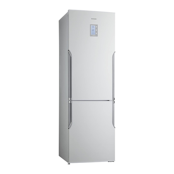
NR-B29SG2
NR-B29SW2
NR-B32SG2
NR-B32SW2
G:Inox-look
W:White
PAGE
Advertisement
Table of Contents

Related Manuals for Panasonic NR-B29SG2


Summary of Contents for Panasonic NR-B29SG2
- Page 1 5 Location of Controls and Components ------------------12 13 Schematic Diagram -------------------------------------------- 79 6 Installation Instructions ---------------------------------------14 14 Exploded View and Replacement Parts List ----------- 80 7 Operating Instructions-----------------------------------------16 8 Service Mode -----------------------------------------------------20 © Panasonic Corporation 2012 Unauthorized copy- ing and distribution is a violation of law.
-
Page 2: Safety Precautions
1 Safety Precautions... -
Page 5: Specifications
2 Specifications 2.1. NR-B29 models Model NR-B29SG2 NR-B29SW2 Destination Europe - France - U.K. Volume capacity Total effective volume capacity 289 L Refrigerator compartment (PC) 217 L Freezer compartment ( FC ) 72 L External dimensions width/ depth/ height (mm) - Page 6 Refrigerator compartment sensor epcos NTC Freezer compartment sensor Ambient temperature sensor Defrost temperature sensor Compressor Model PANASONIC Rotation speed 23 / 42 / 58 (r/s) Curled resistance cord (at 20°C) U-W, U-V, V-W = 7.2 Ohm Overlord relay Model PANASONIC Operating temperature without power 95 ±...
-
Page 7: General/Introduction
3 General/Introduction 3.1. Flow of Refrigerant... - Page 8 3.2. Flow of Air 3.2.1. Inside the Fridge 3.2.2. Flow of Air Through Air Ducts (Front view)
-
Page 9: Technical Descriptions
4 Technical Descriptions 4.1. Setting the temperature 4.1.1. Fridge compartment (PC) At the time of purchase, the temperature is set to 4° 1. Press (upper) once and then press it again within 1 second. • The temperature can be set. 2. -
Page 10: Defrost Control
4.2. Defrost Control 4.2.1. Calculating defrost starting time According to this; a) If ATC < 23 °C Fix the defrost cycle to 16 hours (running + stopping) b) If 23 °C < ATC < 28 °C If door is not opened; First Defrost cycle time will be fixed to 16 hours. -
Page 11: Fan Control
4.3. Fan Control While compressor is running, evaporator fan is running. When compressor stops and if damper motor is closed 2min run - 2 min stop operation starts and continue until compressor runs or damper motor opens again. If ambient temperature is ATC ≤ 22 °C or ATC ≥ 30 °C •... -
Page 12: Location Of Controls And Components
5 Location of Controls and Components 5.1. Display and Control Panel... - Page 13 5.2. Components...
-
Page 14: Installation Instructions
6 Installation Instructions This section explains how to install your appliance for the most energy-efficient, safe and quiet operation. Dimensions NR-B29SG2/NR-B29SW2: W600 x D652 x H1898 (mm) NR-B32SG2/NR-B32SW2: W600 x D652 x H2044 (mm) Unpacking your appliance Remove all packaging and tape. - Page 15 Installing the distance guides To prevent the condenser (the black backside component with fins) from touching the wall, put on two plastic distance guides in its place rotating 90°. Cleaning After installation, wipe the appliance clean with warm water. Connecting the mains plug to the household mains socket You can connect the mains plug immediately after installation.
-
Page 16: Operating Instructions
7 Operating Instructions 7.1. Functions 7.1.1. Super Freeze Mode Features : • In this mode, the FC can be cooled rapidly, enabling the fresh foods, etc. which are placed there to be frozen. • Super Freeze Mode will automatically end after 24 hours or when the FCC sensor tempera- ture becomes lower than -32 °C. -
Page 17: Eco Mode
7.1.3. Eco Mode Features : • In this mode, the control unit operates the FC and PC economically. • In this mode, the PC temperature is automatically set to 4 °C and the FC temperature is automatically set to -18 °C. Settings : 1. -
Page 18: Drink Cool Mode
7.1.5. Drink Cool Mode Features : • Drinks can be cooled quickly in the FC. • This mode has a timer function, and can be set to beep when the timer reaches 5, 10, 15, 20, 25 or 30 minutes. •... -
Page 19: Child Lock Function
7.1.7. Child Lock function Features : • Setting Child Lock can keep children from changing the settings while playing with the but- tons. Settings : 1. Press (upper) and (lower) for 5 seconds to set Child Lock. • While Child Lock is set is lit. -
Page 20: Service Mode
8 Service Mode 8.1. Entering service mode: Push FC selection button continuously. During this time, open and close FC door for 3 times. Appliance will enter service mode 3 sec. later. 8.2. During service mode: • Buzzer will sound beep for 0.1 sec. each 5 sec. during service mode •... - Page 21 4. Push Displaying actual temperatures in compartments Push 4 time to mode button Super Cooling symbol will blink during mode. FC number segment will show F and PC number segment will show FCC sensor actual temperature. If service man pushes FC selection button; Freezer number segment will show [r] and refrigerator number segment will show PCC sensor actual temperature.
- Page 22 8.3. Display sign list SENSOR TEMPERATURE USER MODE REACTION SERVICE MODE REACTION (1) Freezer (FCC) > +50°C or < -50°C Display Sr (blinks) in FC number Display FE 01 (sensor is short or open) segment (2) Refrigerator (PCC) > +50°C or < -50°C Display FE 02 Sr Symbol blinks (sensor is short or open)
-
Page 23: Troubleshooting Guide
9 Troubleshooting Guide 9.1. Not cooling at all [ Both PC & FC (compressor does not operate)]... - Page 24 9.2. PC is not cooling or poor cooling. [ FC cooling condition is normal]...
- Page 25 9.3. FC is not cooling. [ Compressor operate]...
- Page 26 9.4. Cooling system trouble.
- Page 27 9.5. Temperature sensor trouble.
- Page 28 9.6. Temperature sensor trouble.
-
Page 29: Disassembly And Assembly Instructions
10 Disassembly and Assembly Instructions 10.1. Replacement of Display 1. First, stick a tape on the corner of display to prevent any 2. Take out the display panel cover by using a sharp/thin scratches. tipped tool. 3. Try to stretch it from one side, then remove it with your hand by pulling forward. - Page 30 4. Take out the socket from the connector and remove the 6. Tidy up the cables before placing the display to prevent display panel assy. jamming. 5. Connect the sockets to the new display. 7. Place the display and press gently from upper and bottom corners to fit inside the display housing.
- Page 31 10.2. Replacement of Head Panel Group and Main PCB Note: Remove Refrigerator Door beforehand. (See the door way change section) 1. Remove the head panel right cover and left cover. 3. Remove the head panel. 2. Unscrew the screws fixing the head panel. 4.
- Page 32 5. Remove the main PCB box and take out the main PCB. 6. After changing the main PCB insert the new one into the main PCB box and make the connections then mount them to the head panel. Mount the head panel to the panel housing.
- Page 33 10.3. Replacement of PC Upper Mul- 2. Then pull multiflow cover slightly from the right side. tiflow & PCC sensor 1. First remove the glass shelves and bottle holder, then remove PC multiflow caps and unscrew the screws. Note: There are 6 caps and screws for model NR-B32 and 4 caps and screws for model NR-B29 3.
- Page 34 4. Pull multiflow styrofoam slightly from the left side. 6. Take out the sockets and replace the PCC sensor & Multi- flow group. 5. Take out the putty from the socket housing. Reseal the putty and place the styrofoam into its place, also place the PCC sensor to its holder at cover and close the cover.
- Page 35 2. Remove PC bottom multiflow caps (4) and unscrew the screws(5).
- Page 36 3. Pull multiflow bottom group slightly from the left side. 4. Take out the putty from the connector housing and remove the resistance socket and dumper socket. Replace the sensor & Multiflow group. Note: Keep sealing material for re-sealing the con- nectors after replacement.
- Page 37 10.5. Replacement of PC LED 1. Unscrew the 2 screws fixing the PC LED cover and remove it. 2. Unscrew the 2 screws fixing the PC LED box and take out the connector and remove the box. 3. Unscrew the 2 screws fixing the PC LED and replace it.
- Page 38 10.6. Replacement of FC Multiflow 3. Then remove the one screw. Cover 1. Remove 4 caps and unscrew the 4 screws shown at the picture. 4. Then pull second part of multiflow cover slightly from the bottom and rotate to the left side (In case of icing between cover and evaporator, do not pull the cover with full force, slightly shake the cover to brake the icing then pull.)
- Page 39 5. Watch out the fan motor cables go through the multiflow. 7. Cut both the black lead wires which comes from white Remove the sealing material (putty). and pink color connectors. Note: Keep sealing material for re-sealing the con- nectors after replacement. Replace the multiflow cover with new one, follow the steps for fan motor cable connections which described at next part.
- Page 40 Important Notice for F/M & Heater connection Wiring Connection Connecter housing is fixed on the surface of inner liner (Can Not change). To avoid short-circuit (tracking) by moisture, L side and N side should Not be jointed with one connecter. That is the reason of above connection.
- Page 41 How to replace fan motor (Summary)
- Page 42 10.7. Replacement of FC Fan Motor 3. Cut both the black lead wires which comes from white and pink color connectors. Faulty fan motor can be removed from the multiflow cover. Warning: Make sure the unit is unplugged. First you should open the multiflow cover as described at previous sections 1.
- Page 43 6. Take out the fan motor holder and remove the fan motor 9. Pick up the black cables coming from connectors. from it’s place. 10. Place the lead wire (L) to be connected and the spare 7. Cut off the pink connector socket coming with the spare (LS) lead wire in the grooves of part C.
- Page 44 11. Fold part B onto part C until hook at part B is fixed. 13. After connecting the two lead wires, cut the edge of lead wires using a cutter. 12. Fold part A onto part B. Both left hook and right hook at part A should be fixed tightly by pressing with a pliers.
- Page 45 14. Wrap the U-CONNECTOR with silicon tape (brown color) 15. After connecting both cables with U-CONNECTOR, Connect the pink and white connectors to the housing. 16. Re-seal the housing with sealing material.(putty)
- Page 46 10.8. Replacement of Fin Evapora- tor Assy. Warning: This process needs gas defla- tion, gas re-charging and welding pro- cesses so its need to be done by trained professionals. Instructions of gas deflation, gas re-charg- ing and welding processes will be given at appendix as a separate presentation.
- Page 47 5. Place the new Evaporator Assy. to its place, when fixing the Evaporator Assy. press it horizontally otherwise you might damage the fixing plastics. 4. Remove the evaporator by pulling forward in a horizontal direction. Do not push it up or down. You may broke the fixing plastics.
- Page 48 Warning: This process needs gas defla- tion, gas re-charging and welding pro- cesses so its need to be done by trained professionals. Instructions of gas deflation, gas re-charg- ing and welding processes will be given at appendix as a separate presentation. 10.9.
- Page 49 2. Cut off the cable tie ant remove the bitumen covering the 3. To take out the evaporator, tubes need to be cut with oxy- tubes. gen welding. Note: You need to protect the plastic cabinet from the fire of welding with a protector as shown in the below pictures.
- Page 50 6. Remove the tape around defrost sensor and keep the tape for re-sealing. Remove the defrost sensor and ther- mal fuse. Warning: Operator should certainly wear gloves dur- ing evap replacement. 5. Cut the cable ties around the evaporator and sensors. 7.
- Page 51 8. Detach the evaporator from the defrost heater. 9. Place the new evaporator and re-attach the clippers with the help of a pliers.
- Page 52 11. Re-seal the defrost sensor and tie with the cable tie. 10. Tie the tray and thermal fuse to the evaporator with cable tie. 12. Place the new Evaporator Assy. to its place, when fixing the Evaporator Assy. press it horizontally otherwise you might damage the fixing plastics.
- Page 53 13. Weld the pipes with oxygen welding. 15. Re-connect all the connections and re-seal the housing Note: You need to protect the plastic cabinet from the with putty. Tie the cables with cable tie and close the air- fire of welding with a protector as shown in the below flow cover.
- Page 54 10.10. Replacement of Defrost Heater Warning: This process needs gas defla- tion, gas re-charging and welding pro- cesses so its need to be done by trained professionals. Instructions of gas deflation, gas re-charg- ing and welding processes will be given at appendix as a separate presentation.
- Page 55 5. Cut the cable ties around the evaporator and sensors. 4. Remove the evaporator by pulling forward in a horizontal direction. Do not push it up or down. You may broke the fixing plastics. 6. Remove the tape around defrost sensor and keep the tape for re-sealing.
- Page 56 7. Remove the black metal clippers with the help of a screw- driver. ( from both sides of evaporator) 8. Detach the evaporator from the defrost heater. 9. Open the holders at the bottom of the evaporator tray to release the defrost heater.
- Page 57 10. Detach the tray from defrost heater and Attach the new defrost heater to the tray. 11. Place the evaporator and re-attach the clippers with the help of a pliers.
- Page 58 12. Tie the tray and thermal fuse to the evaporator with cable tie. 14. Place the new Evaporator Assy. to its place, when fixing the Evaporator Assy. press it horizontally otherwise you might damage the fixing plastics. 15. Weld the pipes with oxygen welding. Note: You need to protect the plastic cabinet from the fire of welding with a protector as shown in the below 13.
- Page 59 16. Seal the welding point with bitumen (after they cooled down) and tie with cable tie. After welding process mount the fan motor box and make its connections with U-CONNECTOR as told in Fan Motor replacement section. 17. Re-connect all the connections and re-seal the housing with putty.
- Page 60 Instructions of gas deflation, gas re-charging and welding (This is the general information for gas charging) Warning: This process needs to be done by trained professionals. Welding machine Gas Charge Machine Before starting the process take the product in a spacious and good ventilated place. 1.
- Page 61 2. Before welding process make sure that all gas is evacu- 4. Detach the dryer from the main tube using oxygen weld- ated from the system, shake the compressor to evacuate last remnants of gas. (You can blow air from the service tube.) *** Do not perform any operations for min 30 minutes after you break the service tube.
- Page 62 6. Insert the capillary tube at least 1 cm inside the new dryer and weld the connection. 8. Change the service pipe of compressor with new one. Note: Dryer must be changed in every time before gas charging. 7. Curl the capillary tube as in the below picture. Weld the main tube and new service tube to dryer.
- Page 63 9. After all welding processes is done, press nitrogen from compressor and dryer service tubes to check if there any blockage. 10. Blank the service tube on dryer (with welding) and connect the gas charging machine via service tube on compressor for vac- uuming.
- Page 64 11. Check the gas type and amount on label and charge with 13. Check every welding point with a detector or foam against appropriate type and amount of gas. any leakage. 14. After all process, connect the product to an energy moni- tor and check if the consumption values are normal.
- Page 65 10.11. Replacement of Thermal Fuse 10.12. Replacement of DFC Assy. 1. Cut the cable tie. 2. Disconnect to defrost sensor connector. 1. Disconnect thermal fuse connector. (black connector) 3. You can take out the defrost sensor by removing the alu- minum tape on it.
- Page 66 10.14. Replacement of ATC (At the top of the cabinet) 1. Remove the ambient sensor cover by pulling forward and disconnect sensor connector. WARNING: Do not remove the black rubber tube in any case, which placed at the end of water evacuation pipe. 10.15.
- Page 67 3. Remove all 6 socket connections and release the two 2. Unscrew the 4 screws fixing the holders. holder to take out the inverter. Replace with new one con- nect the sockets and fix the screws after placing the cover. 3.
- Page 68 10.18. Changing The Doorway Direc- 2. Take out the switch using a sharp/thin tipped tool. Try to stretch it from one side, then remove it with your hand by tion pulling forward. Warning: Make sure the unit is unplugged. 1. Unscrew the screw fixing the Top Hinge Cover and remove it.
- Page 69 4. Remove the PC Door. 7. Lie down the appliance to the back. (min: 400mm) CAUTION:Do not damage the outer condenser. 5. Unscrew the two screws which are fixing the Middle 8. Unscrew the Stationary Foot under the Bottom Hinge. Hinge and remove the Washer.
- Page 70 10. Unscrew the Stationary Foot on the left side. 13. Screw the Stationary Foot for the right side. 14. Insert the Flat screwdriver into the gap between the Spacer and the Bottom Hinge. Then pry off the Spacer. 11. Unscrew the side panel fixing screws. Unscrew the pin of hinge, rotate the Bottom Hinge 180°.
- Page 71 16. Then screw the Bottom Hinge to the left side. 20. Put up the appliance. 21. Detach a right Bushing, and insert it in the left hole. 22. Remove a left Bushing Cap,and insert it in the left hole. 17. Screw the Stationary Foot for the left side. 23.
- Page 72 25. Insert the new Catcher Left in left. (You can find the new 27. Turn the Middle Hinge upside down and screw it and Catcher Left in the user manuel bag) Washer to the left side. 28. Remove the Catcher Right of PC Door. NOTICE The screw hole is not open.
- Page 73 30. Insert the new Catcher Left in left. (You can find the new Catcher Left in the user manuel bag) 33. Unscrew the Hinge Pin and rotate the pin upside down then fix it to right side of the Top Hinge. NOTICE The screw hole is not open.
- Page 74 35. Assemble the PC Door. 38. Connect the Display Connector. 39. Mount the Top Hinge Cover and screw it. 36. Remove the Socket Cover and attach it on the right side. 37. Screw the Top Hinge fixing screws.
-
Page 75: Measurements And Adjustments
11 Measurements and Adjustments 11.1. Component Controlling 11.1.1. Compressor: Check the compressor windings. If there is any open or short circuit the compressor must have exchanged. IIt pumps the refrigerant absorbed from the cooling system to the condenser. Basically it is consist of a cylinderpiston system and an electric motor. -
Page 76: Defrost Heater
11.1.3. Display 11.1.5. Defrost Heater: Being used in electronic No-frost models. PC & FC settings, Being used to defrost the icing formations. menu & service mode and other settings are being adjusted with display buttons. All settings can be seen via display screen. - Page 77 11.1.7. Damper motor: 11.1.8. Sensor Being used in electronic no-frost models. Sensors used at electronic models shows different resistance It controls the cold air coming from the FC via air duct. values for various ambiance temperatures. Note: These resistance values are indicated below: When to replace damper motor;...
-
Page 78: Dimensions
12 Dimensions... -
Page 79: Schematic Diagram
13 Schematic Diagram... -
Page 80: Exploded View And Replacement Parts List
14 Exploded View and Replacement Parts List 14.1. NR-B32SG2 / NR-B32SW2 14.1.1. Interior Parts... - Page 81 14.1.2. Interior Parts List Safety Ref. Part No. Part Name & Description NR-B32SG2 NR-B32SW2 ASSY URT CAB ASSY URT CAB CNRAE-152950 TOP HINGE GR CNRAC-776860 HEAD PANEL CNRAC-776820 HEAD PANEL AJ-007140 SCREW M5X14 YSB-F CNRAE-159190 MIDDLE HINGE CNRAJ-327780 MIDDLE HINGE SCREW CAP CNRAG-135770 MIDDLE BRACKET SWITCH GR CNRAE-184130...
- Page 82 14.1.3. Multiflow Parts...
- Page 83 14.1.4. Multiflow Parts List Safety Ref. Part No. Part Name & Description NR-B32SG2 NR-B32SW2 AJ-007440 SCREW KA 40X18 YSB-C-INOX AJ-016780 SCREW KA 40X14 YSB-R-F-INOX CNRBF-589230 FIN EVAPORATOR ASSY CNRAF-169400 FIN EVAPORATOR CNRAG-302630 PROPELLER CNRBG-173210 EVAP FAN MOTOR CNRAF-710380 F MULTIFLOW COVER CNRAG-148980 DEFROST SENSOR 433B...
- Page 84 14.1.5. Door Assy Parts...
- Page 85 14.1.6. Door Assy Parts List Safety Ref. Part No. Part Name & Description NR-B32SG2 NR-B32SW2 AJ-007440 SCREW KA 40X18 YSB-C-INOX CNRAE-076170 BUSHING/345P CNRAD-146140 BUSHING CAP CNRAD-315780 BUSHING CAP CNRBD-695280 F DOOR ASSY CNRBD-645570 F DOOR ASSY CNRBD-695230 R DOOR ASSY CNRBD-645520 R DOOR ASSY CNRAJ-153030...
- Page 86 14.1.7. Unit Parts...
- Page 87 14.1.8. Unit Parts List Safety Ref. Part No. Part Name & Description NR-B32SG2 NR-B32SW2 CNRBF-164000 MAIN CONDANSER AJ-097920 SCREW ST 4.8X13 YSB-T-C CNRAH-062350 CABLE HOLDER CNRAF-022100 ANTIVIBRATION (CONDENSER) CNRBG-183550 POWER CORD GR CNRBG-183640 POWER CORD GR AJ-018170 SCREW 4.2X9.5 YSB-C CNRAF-580540 EVAPORATING TRAY GR CNRAJ-016970...
- Page 88 14.2. NR-B29SG2 / NR-B29SW2 14.2.1. Interior Parts...
- Page 89 14.2.2. Interior Parts List Safety Ref. Part No. Part Name & Description NR-B29SG2 NR-B29SW2 ASSY URT CAB ASSY URT CAB CNRAE-152950 TOP HINGE GR CNRAC-776860 HEAD PANEL CNRAC-776820 HEAD PANEL AJ-007140 SCREW M5X14 YSB-F CNRAE-159190 MIDDLE HINGE CNRAJ-327780 MIDDLE HINGE SCREW CAP...
- Page 90 14.2.3. Multiflow Parts...
- Page 91 14.2.4. Multiflow Parts List Safety Ref. Part No. Part Name & Description NR-B29SG2 NR-B29SW2 AJ-007440 SCREW KA 40X18 YSB-C-INOX AJ-016780 SCREW KA 40X14 YSB-R-F-INOX CNRBF-589230 FIN EVAPORATOR ASSY CNRAF-169400 FIN EVAPORATOR CNRAG-302630 PROPELLER CNRBG-173210 EVAP FAN MOTOR CNRAF-710380 F MULTIFLOW COVER...
- Page 92 14.2.5. Door Assy Parts...
- Page 93 14.2.6. Door Assy Parts List Safety Ref. Part No. Part Name & Description NR-B29SG2 NR-B29SW2 AJ-007440 SCREW KA 40X18 YSB-C-INOX CNRAE-076170 BUSHING/345P CNRAD-146140 BUSHING CAP CNRAD-315780 BUSHING CAP CNRBD-736670 F DOOR ASSY CNRBD-588990 F DOOR ASSY CNRBD-736590 R DOOR ASSY...
- Page 94 14.2.7. Unit Parts...
- Page 95 14.2.8. Unit Parts List Safety Ref. Part No. Part Name & Description NR-B29SG2 NR-B29SW2 CNRBF-164000 MAIN CONDANSER AJ-097920 SCREW ST 4.8X13 YSB-T-C CNRAH-062350 CABLE HOLDER CNRAF-022100 ANTIVIBRATION (CONDENSER) CNRBG-183550 POWER CORD GR CNRBG-183640 POWER CORD GR AJ-018170 SCREW 4.2X9.5 YSB-C...
- Page 96 14.3. Packing Exploded View Safety Ref. Part No. Part Name & Description NR-B29SG2 NR-B29SW2 CNRAK-736030 PACKAGE CARTOON CNRAK-736040 PACKAGE CARTOON CNRAK-736050 PACKAGE CARTOON CNRAK-736060 PACKAGE CARTOON CNRAK-736070 PACKAGE CARTOON CNRAK-736080 PACKAGE CARTOON CNRAK-074640 PACKAGE STRIP CNRAK-657670 PAD UPPER CNRAK-643410 PAD LOWER...
- Page 97 14.4. Parts in document bag Safety Ref. Part No. Part Name & Description NR-B29SG2 NR-B29SW2 CNRAJ-327780 MIDDLE HINGE SCREW CAP CNRAE-076170 BUSHING/345P CNRAE-616900 CATCHER LEFT CNRAE-617010 CATCHER LEFT CNRBEE-60570 BOTTOM STOPPER/LEFT CNRBHE-83510 DISTANCE GUIDE CNRBHE-95550 ENERGY LABEL CNRBHE-95770 ENERGY LABEL...
Need help?
Do you have a question about the NR-B29SG2 and is the answer not in the manual?
Questions and answers