
Related Manuals for Blackmagicdesign Teranex Processors

Summary of Contents for Blackmagicdesign Teranex Processors
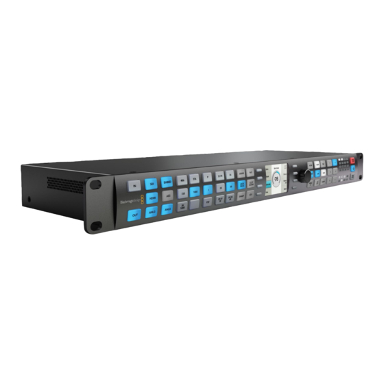
- Page 1 Installation and Operation Manual Teranex Processors Mac OS X ™ Windows ™ June 2013...
- Page 2 Welcome Welcome to Teranex! Thank you for purchasing a Blackmagic Design Teranex converter for your facility. The Teranex converter you have purchased is an amazing quality standards converter that you will spend hours playing with to discover all the wonderful functions it has. I am still playing with it myself to see all the other things I can use it for! We have packed it with the latest SDI, HDMI and analog connections so you can use it to convert and...
-
Page 3: Table Of Contents
Contents Teranex Processors Getting Started Understanding the LCD Menus Introducing Teranex Main Menu Connecting your Teranex Video Menu Operating Your Teranex Color Correction Menu Clip Menu Installing Blackmagic Teranex Software Aspect Menu How to update the Blackmagic Teranex Software ADJ - Adjust Aspect... - Page 4 Contents Teranex Processors Intensity Using Blackmagic System Preferences Depth Using your Favorite Editing Software Camera Align Blackmagic Media Express 3 Align Menu Avid Media Composer 6 Rotation Menu Apple Final Cut Pro 7 Setup Menu Apple Final Cut Pro X...
-
Page 5: Getting Started
Getting Started Getting Started Introducing Teranex Teranex is a high end video format converter and frame synchronizer, capable of extremely high quality image processing, as well as 16 channels of frame accurate audio conversions. You can move from virtually any video standard or format to any other format in real time with literally hundreds of combinations, making Teranex perfect for live and post production applications. -
Page 6: Connecting Your Teranex
ASPECT MENU VIDEO PRESETS AUDIO STATUS PANEL ANAM 14:9 HOME GAIN LOCK Getting Started LBOX CCUT MENU PBOX ZOOM SYSTEM STATUS 59.94 MENU SMART SHARP LOCK ASPECT MENU VIDEO PRESETS Connecting your Teranex REF IN Y/NTSC/PAL IN B-Y IN R-Y IN Y/NTSC/PAL OUT B-Y OUT R-Y OUT... -
Page 7: Operating Your Teranex
Getting Started Operating Your Teranex The Teranex processor features patented processing technology for the highest quality conversion between video standards, frame rates and resolutions. The incredible power of Teranex processing includes: up conversion, down conversion, SD/HD cross conversion, SD/HD standards conversion, cadence detection and removal, noise reduction, adjustable scaling, aspect ratio conversion including Smart aspect, timecode conversion, 16 channel audio processing and more. - Page 8 Getting Started Cadence Detection, Removal and Correction RATE ASPECT MENU VIDEO PRESETS AUDIO STATUS Teranex is unique because it can automatically remove cadence (3:2 pulldown) from video when converting Clean PANEL Clean Cadence 23.98 ANAM 14:9 Cadence HOME GAIN LOCK to 24 fps, even when the footage has been previously edited and suffers from flash fields.
- Page 9 Getting Started Frame Rate Conversion RATE ASPECT MENU VIDEO PRESETS AUDIO STATUS Moving images exist in three dimensions. Firstly, in the horizontal direction, images are made up of individual Clean PANEL FRC Aperture 23.98 ANAM 14:9 Cadence HOME GAIN LOCK pixels.
- Page 10 Getting Started Capture and Playback When connected to a computer with Thunderbolt technology, the Teranex Processor can also be used for cleaning and converting content for authoring as well as video capture and playback for editing, design and effects. Now you can perform high quality conversions and capture all in one pass! With the Teranex Processor and included software, you get compatibility with editing software including Apple Final Cut Pro, Avid Media Composer and Adobe Premiere Pro, plus support for Adobe After Effects, Photoshop, Nuke™, ProTools, as well as the included Blackmagic Media Express and UltraScope software.
-
Page 11: Installing Blackmagic Teranex Software
Before installing any software you will need administrator privileges. Teranex Utility Step 1. Ensure you have the very latest driver. Visit www.blackmagicdesign.com/support Step 2. Open the “Blackmagic Teranex” folder from the disc or downloaded disk image and launch the “Blackmagic Teranex Installer”. -
Page 12: Installing Blackmagic Teranex Software On Windows
Installing Blackmagic Teranex Software Installing Blackmagic Teranex Software on Windows Step 1. Ensure you have the very latest driver. Visit www.blackmagicdesign.com/support Step 2. Open the “Blackmagic Teranex” folder and launch the “Blackmagic Teranex Installer”. Step 3. The software will now be installed on your system. An alert will appear: “Do you want to allow the following program to install software on this computer?”... -
Page 13: Understanding The Video And Audio Connections
Understanding the Video and Audio Connections Understanding the Video and Audio Connections Connecting Video and Audio Hardware Your Teranex Processor includes a wide variety of input and output connections, providing a flexible solution for just about any system configuration you may have. Once you have connected and selected your input video and audio source, the video and audio output signals will be present on all of the output connectors simultaneously. -
Page 14: Analog Audio
Understanding the Video and Audio Connections Analog Audio 13 12 For the Teranex 2D Processor Two methods of connecting analog audio are available for the Teranex 2D Processor: ‚ a DB25 multi-pin connector for connecting 4 channels of balanced analog audio In and Out ‚... - Page 15 Understanding the Video and Audio Connections AES/EBU Audio 13 12 For the Teranex 2D Processor A DB-25 connector is provided for connecting up to 8 input channels (4 pairs) and 8 output channels (4 pairs) of balanced AES/EBU digital audio to the Teranex 2D Processor. An optional breakout cable is required, which is a standard Yamaha format cable for balanced XLR connections.
-
Page 16: Understanding The Control Panel
Understanding the Control Panel Understanding the Control Panel Teranex Processor Control Panel Layout When you use the Teranex Processor as a stand alone format converter and frame synchronizer, the control panel provides intuitive and quick access to critical functions and status. The selection buttons are easy to read multicolored LEDs, which allows you to easily view the current system status. -
Page 17: Input/Output Selection
Understanding the Control Panel Input/Output Selection VIDEO AUDIO FORMAT FRAME RATE ASPECT EMBED 23.98 ANAM 14:9 The IN/OUT section allows you to select whether the front panel is displaying settings related to the Input signal or the Output signal. When selected, the button is lit BLUE and the buttons on the front panel will indicate the current settings for that selected mode. -
Page 18: Audio Selection
Understanding the Control Panel Audio Selection VIDEO AUDIO FORMAT FRAME RATE ASPECT EMBED 23.98 ANAM 14:9 The buttons in the Audio section define the type of audio in use. ‚ When IN is selected in the IN/OUT section, the Audio section buttons will indicate the current input VIDEO AUDIO FORMAT... - Page 19 Understanding the Control Panel Input Format Detection is Automatic The Automatic Input Format Detection feature permits the processor to automatically configure itself for the current video input format. Once you manually define the desired output format, the Auto Input Detection feature provides for automatic, unattended operation.
- Page 20 Understanding the Control Panel Output Format Selection The current Format, Frame and Rate settings will be indicated by BLUE front panel buttons. To change the output format, we recommend that you work from left to right on the control panel. Select the desired format line rate, frame type and frame rate via the control panel buttons, which will turn GREEN if available.
- Page 21 Understanding the Control Panel 720 Formats The 720 Format button will indicate that the line rate of the input or output is 720. When chosen as the output format, the P button will turn GREEN automatically, as a Progressive frame is the only permissible type for 720 signals.
-
Page 22: Format Conversion Table
Understanding the Control Panel Format Conversion Table Output Input Output Input Output Input Output Input 486i59.94 486i59.94 576i50 486i59.94 720p50 486i59.94 720p59.94 486i59.94 576i50 576i50 576i50 576i50 720p50 720p50 720p50 720p50 720p59.94 720p59.94 720p59.94 720p59.94 1080p23.98 1080p23.98 1080p23.98 1080p23.98 1080PsF23.98 1080PsF23.98 1080PsF23.98 1080PsF23.98... - Page 23 Understanding the Control Panel Format Conversion Table Output Input Output Input Output Input Output Input 1080p25 486i59.94 1080p29.97 486i59.94 1080p50 486i59.94 1080p59.94 486i59.94 576i50 576i50 576i50 576i50 720p50 720p50 720p50 720p50 720p59.94 720p59.94 720p59.94 720p59.94 1080p23.98 1080p23.98 1080p23.98 1080p23.98 1080PsF23.98 1080PsF23.98 1080PsF23.98 1080PsF23.98...
-
Page 24: Aspect Ratio Selection
Understanding the Control Panel Aspect Ratio Selection FORMAT FRAME RATE ASPECT MENU VIDEO PRESETS AUDIO STA 23.98 ANAM 14:9 HOME GAIN Aspect ratio conversion (ARC) provided in the Teranex Processor includes fixed modes such as Anamorphic (ANAM), 14x9, Letterbox/Pillarbox (LBOX/PBOX), Center Cut/Zoom (CCUT/ZOOM) and SMART LBOX CCUT conversion. - Page 25 Understanding the Control Panel If you prefer a center cut output rather that letter box, select the CCUT/ZOOM as your aspect ratio selection: 16:9 Ratio Image 4:3 Ratio Display SD to SD conversions A special note must be made concerning the operational modes used for SD to SD conversions. While most SD programming may use a 4:3 aspect ratio, some SD source material may exist in 16:9.
- Page 26 Understanding the Control Panel Upconversion Downconversion 16:9 Ratio Image 16:9 Ratio Image 4:3 Ratio Image 4:3 Ratio Display (correct geometry) (shot with an (incorrect geometry) anamorphic lens) 4:3 Ratio Image 4:3 Ratio Image (incorrect geometry) LBOX/PBOX - Letterbox / Pillarbox If the input aspect ratio is 16:9 and it is passed on to a 4:3 display, as in a down conversion, the LBOX/PBOX aspect ratio will produce a Letterbox output, where the entire image appears vertically centered in the 4:3 display with bars at the top and bottom of the image.
- Page 27 Understanding the Control Panel 4:3 Ratio Image 16:9 Ratio Display This aspect ratio yields an image with no loss of picture information, but the disadvantage is that it does not fill the entire output display. CCUT/ZOOM - Center Cut / Zoom If the aspect ratio of the input video is 16:9 and is to be converted to a 4:3 display, as in a down conversion, the original image will be cropped on the left and right sides, which is often called a “Center Cut,”...
- Page 28 Understanding the Control Panel 14:9 The fixed 14:9 mode is often used as a compromise between Center Cut and Letterbox in down conversions and between Zoom and Pillarbox in up conversions. The 14:9 mode scales the input image to occupy a 14:9 ratio area of the output display.
- Page 29 Understanding the Control Panel SMART FORMAT FRAME RATE ASPECT MENU VIDEO PRESETS AUDIO STA Smart is a non linear anamorphic aspect ratio designed for use when converting a 4:3 source to a 16:9 output 23.98 ANAM 14:9 HOME GAIN without the traditional distortion of an anamorphic stretch. Smart, which is available in up-conversions only, leaves the center portion of the image virtually untouched, while providing increasing amounts of stretch LBOX CCUT...
-
Page 30: Lcd User Interface And Menu Controls
Understanding the Control Panel LCD User Interface and Menu Controls ASPECT MENU VIDEO PRESETS AUDIO STATUS Video Main Menu Setup PANEL ANAM 14:9 HOME GAIN LOCK LCD User Interface Noise Audio Reduction LBOX CCUT MENU The LCD user interface uses a menu displayed on an LCD with 8 associated “soft buttons”. The menu tree PBOX ZOOM Ancillary... -
Page 31: Presets
Understanding the Control Panel Press the pushbutton of the desired parameter. The button will immediately turn green and the MENU VIDEO PRESETS AUDIO STATUS corresponding LCD Menu will be displayed (see below). Turn the rotary encoder to adjust the PANEL HOME GAIN parameter. -
Page 32: Status Leds
Understanding the Control Panel Status LEDs PRESETS AUDIO STATUS PANEL LOCK Audio Status LEDs When illuminated, the Audio Status LEDs will indicate the presence of audio on the active input or output audio channels. The maximum number of channels supported for each audio type are: MENU VIDEO PRESETS... -
Page 33: Panel Lock / Power / Remote Lock
Understanding the Control Panel Panel Lock / Power / Remote Lock AUDIO STATUS PANEL PANEL LOCK Button LOCK The PANEL LOCK button allows you to lock the control panel to prevent accidental changes to system settings. To activate or deactivate, press and hold the button for 3 seconds. When locked, the PANEL LOCK MENU VIDEO PRESETS... -
Page 34: Understanding The Lcd Menus
Understanding the LCD Menus Understanding the LCD Menus The LCD Menu on the control panel provides the primary means for setting the Teranex Processor's parameters. The menu is arranged in a hierarchical, tree structure. Main Menu Press the HOME button on the control panel to access the Main Menu. The Main Menu is the top level menu in the processor’s menu tree and provides access to the top level functions in the menu structure, which are listed below. -
Page 35: Video Menu
Understanding the LCD Menus Video Menu Selecting the Video Menu provides access to the following user functions: ‚ Color – Color Correction ‚ Clip – Luminance and Chrominance clipping ‚ Aspect – Adjustable aspect ratio menu; fill color selection for pillar and letterbox outputs ‚... -
Page 36: Clip Menu
Understanding the LCD Menus Clip Menu The Clip menu allows you to clip luminance and chrominance (Y & C) overshoots and undershoots from the incoming video signal. The Clip function is not defined as a "legalizer"; however, adjusting the luminance and chroma settings will assist in obtaining the desired output video levels. -
Page 37: Adj - Adjust Aspect
Understanding the LCD Menus ADJ - Adjust Aspect The “Adjustable Aspect” menu provides you with tools that provide valuable image manipulation capabilities. You can adjust the size and aspect ratio of the source image, change the position of the source image in the output, and trim (mask) the edges of the source image. -
Page 38: Aspect Fill
Understanding the LCD Menus Test Adjust Zoom / Color Video Aspect Video Main Menu Setup Horiz Position Horizontal Size Patterns Aspect Crop Noise Aspect Clip Advanced Audio Vertical Position Fill Reduction Ancillary Aspect Trim Data Proc Reset Back Back Back Back Main Menu Video... -
Page 39: Zoom/Crop
Understanding the LCD Menus Zoom/Crop The purpose of Zoom/Crop is to mask video disturbances that may arise at the top, bottom, left or right sides of an image by trimming the image slightly. With one button push, Zoom/Crop will instantly zoom the image vertically by 3 lines and horizontally by 3 pixels and then crop the image by the same amount. - Page 40 Understanding the LCD Menus Test Color Video Video Main Menu Setup Gain Set Value Black Patterns Noise Clip Advanced Audio Saturate Reduction Ancillary Aspect Sharp Data Proc Reset Back Back Back Main Menu Video Proc Amp / Gain Please note that the R-Y and B-Y selection will open another menu page, as shown below Test Color Video...
-
Page 41: Test Patterns Menu
Understanding the LCD Menus Test Patterns Menu The internal video test signal generator will provide Blackburst output and the test patterns shown below. You may add audio test tones to your output via the Audio Mapping feature in the Audio Main Menu. Test SMPTE Color... -
Page 42: Advanced Menu
Understanding the LCD Menus Advanced Menu The Video Advanced menu provides access to the following user controls. ‚ Clean Cadence – Forces the creation of a clean 3:2 sequence in the output video. ‚ Scene Detect – Scene change detection prevents blending of scenes at scene boundaries. ‚... -
Page 43: Scene Detection
Understanding the LCD Menus Scene Detection The Scene Detection menu allows you to enable scene cut (or scene change) detection, which will preserve clean cuts between scenes. Upon detecting a cut, the temporal aperture is reduced from 4 fields to 2 fields for the first frame of the new scene. -
Page 44: Frame Rate Conversion Aperture
Understanding the LCD Menus Test Clean Color Video Video Main Menu Setup Source Type Patterns Cadence Auto Noise Scene Clip Advanced Audio Reduction Detect Video Source Ancillary Aspect Film Data Type Proc Back Back Back Aperture Main Menu Video Advanced / Source Type Frame Rate Conversion Aperture FRC Aperture allows you to adjust the interpolation aperture during frame rate conversions. -
Page 45: Noise Reduction Menu
Understanding the LCD Menus Noise Reduction Menu The Noise Reduction algorithm is a motion adaptive temporal recursive filter that works well in removing random and Gaussian noise. Each pixel is labeled as motion, no motion, or noise. Each of these classes of pixels is treated differently in the noise reduction process. -
Page 46: Bias
Understanding the LCD Menus Bias The Bias level sets the aggressiveness of the noise reduction. The higher the Bias value, the more aggressive the noise reduction will be. ‚ The range is -6 to +6. ‚ The default value is 0. Video Main Menu Setup... -
Page 47: Red Overlay On/Off
Understanding the LCD Menus Red Overlay On/Off In the Red Overlay mode, pixels that are interpreted as being “in motion” will be colored red. The red overlay helps to identify how pixels are being processed by the temporal recursive noise reduction filter. ‚... -
Page 48: Closed Caption Menu
Understanding the LCD Menus Closed Caption Menu The Closed Caption menu allows you to configure the closed caption functions in the system for CEA-608B and CEA-708B standards, depending on the format conversion being performed. In NTSC analog video and SMPTE 259M digital video systems, CEA-608B is the reference standard and captions are encoded on line 21 of the vertical blanking interval (VBI). - Page 49 Understanding the LCD Menus CC Enable The CC Enable menu allows you to turn closed captioning ON or OFF in the output video of the Processor. Disabling the captions may be helpful if the incoming closed caption data is incorrect or corrupt. ‚...
- Page 50 Understanding the LCD Menus Analog Out Line The Analog Out Line selection is used to identify the line on which closed caption information will be located in the output video. This menu applies only to the analog SD output. ‚ The range of adjustment is lines 20 to 22. ‚...
- Page 51 Understanding the LCD Menus Service 1 Language The Service 1 Language menu allows you to select the language for that Service in CEA-708 closed captions. ‚ The language choices are: - English - French - German - Italian - Spanish ‚...
-
Page 52: Timecode Menu
Understanding the LCD Menus Closed Service 1 Video Main Menu Setup Ancillary Data Select Language Caption Enable Language English Noise Analog Service 2 Audio Timecode Reduction In Line Language French Ancillary Video Analog German Data Index Out Line Italian Service 2 Back Back Back... - Page 53 Understanding the LCD Menus ‚ Mode Select– When Mode is selected, five available timecode modes will be displayed. Detailed descriptions for each mode are provided on the following pages. - Off (default) - Generate - Input - Jam Sync - Input Regen ‚...
- Page 54 Understanding the LCD Menus Input Line By default, the timecode Input Line selector is set for AUTO detect, where the system scans each input video frame for timecode. The Input Line selector allows you to manually select the line on which timecode is located, which may be useful if the timecode is not detected via the AUTO detect mode.
- Page 55 Understanding the LCD Menus Closed Mode Input Timecode Video Main Menu Setup Ancillary Data Timecode Setup Set Value Caption Select Line Source Noise Start Output Audio Timecode Reduction Timecode Source Line Ancillary Video Prev Next DF Mode Data Index Back Back Start Back...
- Page 56 Understanding the LCD Menus Timecode Source In the Teranex 3D Processor, the Timecode Source menu allows you to select your source for timecode input to the processor. The choices are: ‚ ATC / VITC (default) ‚ LTC The default setting is ATC / VITC, which is embedded in the SDI video input signal. If you are using a device that supplies timecode via a separate cable, such as a VTR, your should connect the timecode source to the LTC connector on the rear panel..
- Page 57 Understanding the LCD Menus ‚ Start Value – A specific timecode value will be used when the timecode generator is started. The desired value will be entered in the Generate or Jam Sync menus. ‚ Input – The timecode present on the input video source will be used by the timecode generator. If no timecode is present, the generator will start at 00:00:00:00.
- Page 58 Understanding the LCD Menus Input Mode Select Input to route or copy the input timecode directly to the output. This is useful when the frame rates of the input and output are the same and you want to preserve the original timecode. It’s important to make sure that the Drop Frame mode in the timecode Setup menu is set to Auto to ensure the output timecode will match the input timecode.
- Page 59 Understanding the LCD Menus In Input Regen mode, drop frame and non drop frame modes are both supported in 23.98, 29.97 and 59.94 frame rates. However, in a conversion where the source timecode is drop frame and the video output format does not support drop frame timecode, (e.g.
- Page 60 Understanding the LCD Menus If the Start Source menu is set to “Start Value,” the Set Timecode menu will display an eight-character register that will permit you to enter a specific timecode generator Start Value. Turn the rotary encoder to adjust the timecode generator values.
-
Page 61: Video Index Menu
Understanding the LCD Menus If the Start Source menu is set to “Start Value,” the Set Timecode menu will display an additional eight character register that will permit you to set a specific Start Value for the timecode generator. (As before, the Jam Sync register will be used to enter the Jam Sync value.) Turn the rotary encoder to adjust the timecode values. - Page 62 Understanding the LCD Menus Closed Index Video Main Menu Setup Ancillary Data Index Reaction Caption Reaction Noise Audio Timecode Reduction Insertion Ancillary Video Data Index Insert Line Back Back Back Main Menu Ancillary Data Video Index / Index Reaction AFD Insertion Menu This menu allows you to select the desired AFD code that will be inserted in the output video.
-
Page 63: 3D Menu
Understanding the LCD Menus AFD Insert Line Menu If AFD Insertion is enabled in the AFD Insertion menu above, the AFD Insert Line menu allows you to select the line on which the AFD code will be inserted in the ancillary data space of the output video signal. ‚... -
Page 64: 3D Mode
Understanding the LCD Menus 3D Mode In the 3D Mode menu, “Off” implies normal 2D processing. The following selections are available to enable 3D processing: ‚ 3D Convert – This mode enables processing of stereoscopic left and right eye inputs, which may be input via the SDI or HDMI inputs. -
Page 65: Input
Understanding the LCD Menus Input The 3D Input menu allows you to define the input formatting of your 3D source. ‚ Full Frame – Full resolution inputs for left and right eye images on SDI inputs A and B, respectively, or from an HDMI frame packed signal if using the HDMI input. -
Page 66: Intensity
Understanding the LCD Menus Intensity The Intensity selection will not be available until 2D to 3D has been selected in the 3D Mode menu. The Intensity setting allows you to control the amount of overall 3D effect. ‚ The range of adjustment is -40 (image is in front of the screen) to +40 (image is behind the screen). The default setting is +15. -
Page 67: Camera Align
‚ Default Settings – As with other menus in the Teranex Processors, you may push the rotary encoder to return the current parameter to its default setting. Use the “Reset All” menu button to return all controls in the current menu to their default settings. -
Page 68: Rotation Menu
Understanding the LCD Menus Left Video Main Menu Setup 3D Mode 3D Mode Intensity Align Camera Align Zoom Horiz Align Noise Right Audio Input Depth Rotation Trim Vertical Reduction 3D Convert Ancillary Camera Both 2D to 3D Output Flip Data Align Eyes 3D Align... - Page 69 Understanding the LCD Menus Original Image Roll Z-Axis Tilt Adjustment - X Axis The Tilt X adjustment provides image rotation on the X axis. ‚ The range of the adjustment is -8 to +8 degrees on the X axis. The default setting is 0. ‚...
- Page 70 Understanding the LCD Menus Toe-In Adjustment - Y Axis The Toe-in Y adjustment provides image rotation on the Y axis. ‚ The range of the adjustment is -8 to +8 degrees on the Y axis. The default setting is 0. ‚...
- Page 71 Understanding the LCD Menus Left 3D Mode 3D Mode Intensity Align Camera Align Zoom Video Main Menu Setup Flip Flip Noise Right Input Depth Rotation Trim Audio Reduction 3D Convert Horizontal Ancillary Camera Both 2D to 3D Output Flip Vertical Align Data Eyes...
- Page 72 Understanding the LCD Menus Zoom Menu The Camera Align Zoom menu permits you to zoom the left and right images in the horizontal and vertical directions independently, or in both directions simultaneously. ‚ A negative parameter indicates zooming OUT on the image, while a positive parameter indicates zooming IN on the image.
- Page 73 Understanding the LCD Menus Trim Menu The Camera Align Trim menu permits you to trim the image in the horizontal and vertical directions independently or in both directions simultaneously. ‚ The range of the trim is dependent on the video format in use. ‚...
- Page 74 Understanding the LCD Menus Connections and Other Important Information for 3D Modes Let’s go over some of the connections you should be aware of and the ancillary data handling that may affect your workflow. Video Connections Stereoscopic left & right video inputs should be connected to SDI inputs A and B, respectively. Similarly, left and right processed outputs will be available at SDI outputs A and B, respectively.
-
Page 75: Setup Menu
Understanding the LCD Menus External Reference The output streams may be synchronized to either Input A or to an external reference of Blackburst or Tri-level sync supplied to the REF rear panel connector. You may select the reference Type in the Setup / Reference LCD menu. - Page 76 Understanding the LCD Menus ‚ For SD interlaced output formats (e.g. 486i59.94, 576i50), ONLY blackburst (BLACK) may be used. The frame rate must match the output format (59.94 or 50). ‚ For HD interlaced output formats (e.g. 1080i59.94, 1080i50), either blackburst (BLACK) or tri-level interlaced (TRI-I), in the respective frame rate (59.94 or 50), may be used.
-
Page 77: Line Offset
Understanding the LCD Menus Line Offset This control adjusts the Line timing of the output relative to the external reference selected. ‚ The Range is determined by the current output format selection. Video Main Menu Setup Reference Setup Type Line Offset Line Noise Audio... -
Page 78: No Input Menu
Understanding the LCD Menus No Input Menu This menu allows you to define whether Black or Colorbars will be output when there is a loss of input video. ‚ The default setting is Black. Output No Input No Input Video Main Menu Setup Reference... -
Page 79: Output Sampling Menu (For Teranex 3D Processor Only)
Understanding the LCD Menus Output No Input Analog Output Video Main Menu Setup Reference Setup Dual Link Component Input Noise Audio Video Analog Reduction Composite Output Ancillary Audio Analog Data Output Back Back Back Sampling Main Menu Setup Video / Output Analog Output Sampling Menu (for Teranex 3D Processor only) The Output Sampling menu allows selection of the following sampling types for the Teranex 3D Processor. -
Page 80: Audio Setup Menu
Understanding the LCD Menus Audio Setup Menu The Audio Setup menu allows you to select the analog audio input source that you want to use on the rear panel. The choices for Teranex 3D Processor are the RCA Phono or XLR. The choices for Teranex 2D Processor are RCA Phono or DB25. -
Page 81: Audio Mapping
Understanding the LCD Menus Audio Mapping The Audio Mapping menu allows you to map any incoming audio channel or test tone to any output channel. After selecting the desired output channel via the menus described below, you may select from any available audio source, including analog, embedded SDI, AES, decoded Dolby channels and test tones. - Page 82 Understanding the LCD Menus Several examples of mapping choices are shown below. Prev Next Audio Video Main Menu Setup Audio Output Output Mapping Output Channel Noise Audio Input 1 Reduction Input 2 Reset Ancillary Input 3 Data Input 4 Input 5 Back Back Back...
-
Page 83: Capture And Playback
Capture and Playback Capture and Playback VIDEO AUDIO FORMAT FRAME RATE ASPECT MENU VIDEO PRESETS AUDIO STATUS PANEL EMBED 23.98 ANAM 14:9 HOME GAIN LOCK LBOX CCUT MENU HDMI 1080 PBOX ZOOM SYSTEM STATUS 29.97 59.94 MENU ANLG ANLG SMART SHARP 1080 LOCK... -
Page 84: Testing Capture And Playback
Capture and Playback Testing Capture and Playback Teranex 2D It's a good idea to run a quick test to ensure you can capture and play back video before you need to use your Teranex Processor hardware for anything important: HDMI ‚... -
Page 85: Using Blackmagic System Preferences
Video and Audio connections All of the SDI, HDMI and analog video and audio outputs of Teranex Processors are active all of the time. Analog video users will need to choose between component or composite analog video output. Composite analog video only supports standard definition video. - Page 86 Capture and Playback Progressive HD1080 video playback switch Choose between 1080PsF and 1080p on playback. Remove Field Jitter When interlaced video is paused on old CRT monitors, eliminate field flicker by only displaying a single field. We do not recommend using this option with modern flat screens. Progressive HD1080 video playback switch Set default video standard On Mac OS X, if you want to use broadcast monitoring with Final Cut Pro X, set the video standard in these...
- Page 87 Capture and Playback VITC Reader A Frame - Reverse 3:2 Pulldown This option decodes the VITC and uses it to correctly locate the A-frame when performing reverse 3:2 pulldown while capturing video at 23.98fps. Carefully set the correct A-frame VITC reference to match the timecode on tape.
-
Page 88: Using Your Favorite Editing Software
Capture and Playback Using your Favorite Editing Software When connected to a computer with Thunderbolt technology, your Teranex Processor can be used as a powerful editing solution for video capture, conversion and playback. The Teranex Installer software installs Blackmagic system preferences which allow your favorite video editing software to work with your Teranex Processor. -
Page 89: Blackmagic Media Express 3
Capture and Playback Blackmagic Media Express 3 Blackmagic Media Express software is included with every Teranex Processor. Media Express 3 lets you batch capture and play back in DPX, ProRes, uncompressed YUV and RGB, DVCPRO 50 and DVCPRO HD files. Media Express 3 also supports CMX EDL import, frame accurate deck control via RS-422, and will even insert and assemble to tape! Media Express is fast, accurate, easy to use and works on Mac OS X and Windows. -
Page 90: Capturing Video And Audio Files
Capture and Playback Edit to Tape After clicking the blue Edit to Tape tab, select clips from the media list to be mastered to tape using RS-422 device control. Set the In/Out points for your edit and choose between Assemble or Insert edit. You can even preview before mastering to tape. - Page 91 Capture and Playback Media List Timecode List, Thumbnail and Favorites view Search Field VTR / deck timecode Video Preview Project name, video format Clip Bins Mark In / Grab Still Logging Capture Transport Audio channel Audio Meters Remote and frame rate Mark Out Frame Information...
- Page 92 Capture and Playback Capture Capturing video is easy and all you need to do is connect a video source, set the Media Express preferences and press the Capture button. Start by connecting your video source to an input of your and check that the video input Teranex Processor buttons are set to the same video input, e.g.
- Page 93 Capture and Playback Batch Capture After logging a clip, you can click the Clip button if you just want to capture a single clip. If you want to capture multiple clips, continue logging all the clips that you wish to batch capture. When logging is completed, select the logged clips in the Media List and: ‚...
- Page 94 Capture and Playback 3D Capture When Media Express is used with a Blackmagic video hardware model which supports dual-stream 3D, you can create left and right eye 3D video clips by capturing 2 streams of HD-SDI video simultaneously. ‚ Create a 3D project which matches the frame rate of your dual stream 3D video source. ‚...
- Page 95 Capture and Playback Media List Timecode List, Thumbnail and Favorites view Search Field VTR / deck timecode Video Preview Project name, video format Clip Bins Mark In / Clip Grab Still Favorites Transport Audio channel Audio Meters Remote and frame rate Mark Out Information Frame...
-
Page 96: Playing Back Video And Audio Files
Capture and Playback Playing back Video and Audio Files Importing clips You can play back your video and audio files, after importing media into Media Express, in any of the following ways: ‚ Double-click an empty area of the Media List. ‚... -
Page 97: Browsing Media
Capture and Playback Browsing Media In the Media List, you can view your clips in Thumbnail view or Timecode List view by clicking on the desired view button at the top-right of the Media List. In the Media List, choose to view your clips in Timecode List view Thumbnail view or Thumbnail view. - Page 98 Capture and Playback Creating and using favorites In the Log and Capture tab, click the "star" icon next to the Name field if you want to log a clip as a favorite. In the Playback tab, clicking the "star" icon will make the clip a favorite if it is selected in the Media List. Click the "star"...
- Page 99 Capture and Playback Mark In / Record Master to Audio channel Mark Out Modes Tape enable/disable...
- Page 100 Capture and Playback Editing Video and Audio Files to Tape Mastering your clips to a deck is easy. While we usually talk about mastering or editing to "tape", it doesn't matter if your deck uses tapes or disks. To master your clips: ‚...
-
Page 101: Avid Media Composer 6
Capture and Playback Avid Media Composer 6 Avid Media Composer captures and plays back standard definition and high definition video and audio with Teranex Processor hardware, and also supports RS-422 deck control. Blackmagic plug-ins for Media Composer are automatically installed if Media Composer is installed before the Desktop Video software. You can use the buttons on your Teranex Processor to select your video and audio connections including SDI, analog and HDMI, as well as other settings such as up, down and cross conversion, reference clocking and HD progressive frame type. - Page 102 Capture and Playback Capture from Non-Controllable devices Many video sources including all kinds of modern cameras and disk recorders, as well as old cameras and VHS tape players, do not have any device control. To capture video without deck control: Step 1.
- Page 103 Capture and Playback Capture from Controllable devices If you have a deck which connects via RS-422, you will need to configure the deck settings before performing a capture with deck control: Step 1. From your project window, click the Settings tab and double-click on Deck Configuration. Step 2.
- Page 104 Capture and Playback Batch Capture To log clips for batch capture: Step 1. Choose Tools > Capture to open the Capture Tool. Step 2. Click on the Capture/Log Mode button so it displays the LOG icon. Step 3. Configure video and audio input, video and audio source tracks, target bin, res, target drive and tape name the same way as in "Capture from non-controllable devices".
-
Page 105: Apple Final Cut Pro 7
Capture and Playback Apple Final Cut Pro 7 “Easy Setups” for Final Cut Pro 7 are automatically installed if Final Cut Pro is installed before the Teranex software. The Teranex Processor is fully compatible with Apple’s RT Extreme ™ real time effects. Setting up Step 1. - Page 106 Capture and Playback Capture from controllable devices To capture with RS-422 deck control, choose File > Log & Capture. (Command + 8) Your video deck will respond in the same way as a clip in the timeline, via the “<spacebar>”, “j”, “k” and “l”...
-
Page 107: Apple Final Cut Pro X
Capture and Playback Apple Final Cut Pro X If you want to use Final Cut Pro X to play back video on an external video monitor or TV, you can use the broadcast monitoring feature of Final Cut Pro X 10.0.4 and newer to output your video through Teranex Processor hardware. - Page 108 Capture and Playback Playback Step 1. Import some clips in to your new project. Step 2. You can now use the Final Cut Pro X timeline on your computer monitor and view the video preview on the monitor or TV connected to the output of your Teranex Processor. Capturing Video and Audio You can use Blackmagic Media Express to capture video and audio with your Teranex Processor.
-
Page 109: Adobe Premiere Pro Cs6
Capture and Playback Adobe Premiere Pro CS6 Setting up a Blackmagic Design project Step 1. Launch Premiere Pro. Step 2. Create a New Project and click on the Scratch Disks tab. Step 3. Set the desired Location and Name for your project at the bottom of this window. Step 4. - Page 110 Capture and Playback Device Control The Teranex Processor features RS-422 device control for controlling decks. Blackmagic Device Control needs to be selected each time a new project is created. Go to Preferences > Device Control and select "Blackmagic Device Control". The Options button is disabled as the settings are automatically detected and configured when you choose Blackmagic Device Control.
- Page 111 Capture and Playback Batch Capture If you wish to batch capture using RS-422 deck control, select the clips you wish to capture by drag-selecting or shift-clicking each clip. Then choose: File > Batch Capture [F6]. To set handles on the clips, enable the option to Capture with handles and type the number of additional frames you require at the start and end of each clip.
-
Page 112: Adobe After Effects Cs6
Capture and Playback Adobe After Effects CS6 How to use Blackmagic as a preview output frame buffer To allow your Adobe After Effects composition to be displayed in real-time through your Teranex Processor, go to Preferences > Video Preview. Select Blackmagic Video Output and the appropriate Output Mode. This lets you view your Adobe After Effects compositions in the correct video colorspace on your broadcast monitor as you work. -
Page 113: Adobe Photoshop Cs6
Capture and Playback Adobe Photoshop CS6 How to grab and output video frames Import an image into Photoshop Step 1. From Photoshop select File > Import > Blackmagic Image Capture Step 2. Select the “Video Input Format” and the “Image Bit Depth” and then click Capture Image Export an image from Photoshop Step 1. -
Page 114: Waveform Monitoring
Waveform Monitoring Waveform Monitoring VIDEO AUDIO FORMAT FRAME RATE ASPECT MENU VIDEO PRESETS AUDIO STATUS PANEL EMBED 23.98 ANAM 14:9 HOME GAIN LOCK LBOX CCUT MENU HDMI 1080 PBOX ZOOM SYSTEM STATUS 29.97 59.94 MENU ANLG ANLG SMART SHARP 1080 LOCK VIDEO AUDIO... -
Page 115: Using Blackmagic Ultrascope For Waveform Monitoring
1280 x 800 pixels to view two scopes simultaneously. Blackmagic Design recommends viewing all 6 scopes simultaneously by using a computer display resolution of 1920 x 1200 or 1920 x 1080 pixels. Please see the support pages at www.blackmagicdesign.com for a comprehensive list of the latest minimum system requirements for Blackmagic UltraScope. - Page 116 Waveform Monitoring Blackmagic UltraScope Interface 1. Parade Display 2. Waveform Display 3. Vectorscope Display 4. Histogram Display 6. Audio Metering Display 7. Picture Display 5. Error Logging...
-
Page 117: Understanding Blackmagic Ultrascope Views
Waveform Monitoring Understanding Blackmagic UltraScope Views Blackmagic UltraScope has two different views available depending on your workflow needs and screen resolution. You have the choice of viewing six displays in “Full Screen” view, or for more compact viewing, choose any 2 displays in “2-up” view. The display view can be selected from the menu. -
Page 118: Zoom Function
Waveform Monitoring Zoom Function Blackmagic UltraScope allows you to zoom in on various displays for a more detailed analysis. This helpful function will also pan and zoom the graticules for each display in high resolution. The zoom function is available in the Parade, Waveform, Vectorscope and Picture displays. To zoom in, simply click on the bottom right of each respective display. -
Page 119: Waveform Display
Waveform Monitoring Waveform Display The Waveform Display is similar to traditional composite waveform monitors seen in many broadcast studios. On Mac OS X, B/W is always selected to show the luminance view, which provides a digitally encoded waveform similar to traditional luminance waveform monitors. The luminance view is very useful when adjusting luma (brightness) levels in an image. -
Page 120: Vectorscope Display
Waveform Monitoring Vectorscope Display The Vectorscope Display uses a vector view to show the colors in a video signal. You can see color bar video levels by using the color boxes in the graticule. All you need to do is select 75% or 100% color bars, depending on the standard of color bar test signals used in your facility! Some people think you can use a vectorscope to check for illegal levels. -
Page 121: Histogram Display
Waveform Monitoring Histogram Display Histogram Display is most familiar to graphic designers and camera operators. Histogram Display shows the distribution of white to black information and lets you monitor how close the detail is to being clipped off in the whites or blacks of the video. Histogram Display also lets you see the effects of gamma changes in the video. - Page 122 Waveform Monitoring Error Logging Display Error Logging records errors in video and audio and is indispensable when reviewing video and for unattended operation. Errors may be logged for color, brightness or audio threshold levels as well as loss of video signal, change of video format or audio silence. After setting the parameters which define when an error should be logged, you can choose to start or stop error logging, save the log to a file, or clear the log.
- Page 123 Waveform Monitoring How to Customize Error Logging To customize error logging, go to the Error Logging menu and choose Profiles to open the Error Logging Profiles window. Saved profiles appear in the profile list at the left and the current, active profile appears in bold above the list.
-
Page 124: Audio Metering Display
Waveform Monitoring Audio Metering Display Audio Metering Display shows you the audio levels in the embedded audio of the Teranex Processor's video signal. The 8 channels of embedded audio from your Teranex Processor are de-embedded and then displayed in either dBFS or VU format. The VU button switches between dBFS and VU audio metering standards. -
Page 125: Picture Display
Waveform Monitoring Picture Display The Picture Display is a handy confidence monitor so you can see the video that is being received by Blackmagic UltraScope. The Picture Display has three settings: COLOR, B/W (black & white) and BLUE (Blue Only). Set to COLOR or B/W depending on the needs of your facility. -
Page 126: Blackmagic Desk Speed Test
Blackmagic Desk Speed Test Blackmagic Disk Speed Test What is Blackmagic Design Disk Speed Test? Blackmagic Disk Speed Test is a beautiful and fun to use application that measures the read and write performance of storage media in video frame sizes. The use of video frame sizes provides accurate measurement of how the disk storage will perform with video related applications. - Page 127 Blackmagic Disk Speed Test Settings Click this button to access the settings before running a disk speed test START Click this button once to start the disk speed test. Click again to stop the test Will it Work? How Fast? This panel shows which This panel shows results video formats can be...
- Page 128 Blackmagic Disk Speed Test Start Once you have chosen the desired settings, click the Start button to commence the disk speed test. Disk Speed Test will write a temporary file to the selected target drive. When the file has finished writing, or when 8 seconds has elapsed, Disk Speed Test will stop writing and start reading back the temporary file from the drive.
-
Page 129: Developer Information
The list is just for developers. Contacting Blackmagic Design developer assistance You can also contact us via developer@blackmagicdesign.com if you have any developer related questions or wish to ask questions off the list. -
Page 130: Help
After checking the version of Blackmagic Teranex software installed on your computer, please visit the Blackmagic Support Center at www.blackmagicdesign.com/support to check for the latest updates. While it is usually a good idea to run the latest updates, it is a wise practice to avoid updating any software if you... -
Page 131: Warnings
Warnings Warnings Caution: Risk of Electric Shock On the Teranex Processor enclosure you will see a yellow warning label marked ‘Caution: Risk of Electric Shock’. This is intended to warn users that there may be the presence of uninsulated “dangerous” voltage within the Teranex Processor enclosure which may be of sufficient magnitude to constitute a risk of electric shock to the user. -
Page 132: Warranty
Warranty Warranty 12 Month Limited Warranty Blackmagic Design warrants that the Teranex family products will be free from defects in materials and workmanship for a period of 12 months from the date of purchase. If a product proves to be defective during this warranty period, Blackmagic Design, at its option, either will repair the defective product without charge for parts and labor, or will provide a replacement in exchange for the defective product.
Need help?
Do you have a question about the Teranex Processors and is the answer not in the manual?
Questions and answers