Table of Contents
Advertisement
Advertisement
Table of Contents

Summary of Contents for Hallmark Variable Speed 2 Stage
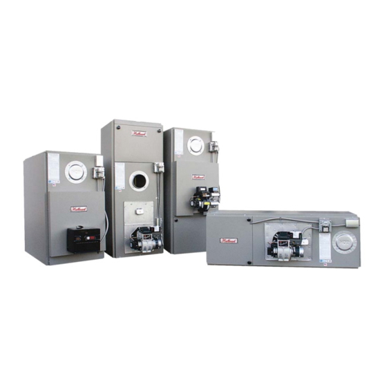
- Page 1 Hallmark Oil Fired Furnace Installation and Operation Instruction Manual Variable Speed 2 Stage ECM Motor Keep these instructions with the furnace at all times for future reference Boyertown Furnace Co. PO Box 100 Boyertown, PA 19512 610-369-1450 www.boyertownfurnace.com 7/1/08...
- Page 2 Be Aware of Hazard Definitions Denotes presence of a hazard which, if ignored, will result in severe personal injury, Danger death or property damage Denotes presence of a hazard which, if ignored could result in severe personal injury, Warning death or substantial property damage. Denotes the presence of a hazard, which if ignored, could result in minor personal injury Caution or property damage...
-
Page 3: Table Of Contents
TABLE OF CONTENTS Page No. Furnace Specifications …………………..………………………………………..4 Installation Clearances ……………………………………………………………….5 Standard Clearances Reduced Clearances Duct Work ……………………………………………………….……………...……….7 Sizing Blower Specifications Filter Racks Multiple Furnace Installation ECM Motor ……………………………………………………………………………….9 Operating Modes Air Flow Selection Electrical Connections Venting …………………………………………………………….………………...……11 Chimney Venting Chimney Relining Chimney Connector Power Venting... -
Page 4: Furnace Specifications
H a llm a rk S p e ci fic a ti o n s M o d e L B D 8 5 L B D 1 1 5 L B D 1 4 5 L B D 1 6 0 H B D 8 5 H B D 1 1 5 H B D 1 4 5... -
Page 5: Installation Clearances
Installation Clearances Furnaces in rooms shall be installed with the clearances from combustible materials not WARNING less than indicated in Table 1. Combustible materials are those made of or surfaced with wood, compressed paper, plant fibers, plastics, or other material that will ignite and burn, whether flame proofed or not, or whether plastered or not. - Page 6 With all clearance reduction systems using ventilated air space there shall be at least 1” clearance between the reduction systems using ventilated air space. Mineral wool batts, blanket or board shall have a minimum density of 8lb/ft and a minimum melting temperature of 1500 Insulation material used as part of a clearance reduction system shall have a thermal conductivity of 1.0(Btu/In)/ (Ft...
-
Page 7: Duct Work
Duct Work NOTICE The duct system should follow the design standards of Air Conditioning Contractors of America (ACCA) or ASHRAE. The duct system should be sized for the maximum CFM capabilities of the furnace being installed. All trunk lines, take-offs, registers and grill free areas must be figured when determining the air handling capacity of a duct system. - Page 8 listed may result in objectionable air noise in the ducts. Table 3 Recommended Maximum Duct Velocities, Feet Per Minute (FPM) Main Ducts* Branch Ducts Application Supply Return Supply Return Apartments Auditoriums 1200 1000 1000 Banks 2000 1500 1600 1200 Hotel Rooms 1500 1300 1200...
-
Page 9: Ecm Motor
MULTIPLE FURNACES IN COMMON DUCT WORK WARNING Multiple furnaces connected to common duct work, either supply, return, or both supply and return must be wired so that all furnace blower motors are energized at the same time. Failure to turn all blowers on at the same time can cause a reversal of air flow in those units where the blower motor is not operating. -
Page 10: Air Flow Selection
No change in air flow will occur unless the motor has been allowed to a complete stop. See figure below for the location of the heating and cooling DIP switches. Hallmark 85 shown as typical. -
Page 11: Venting
ECM Motor Connections The operation of the motor requires two main connections: the power input connector which is 120VAC, and the signal input connector from a 24VAC thermostat. Figure 1 shows the location of the connectors on the motor. When wiring your ECM 2.3, the pin locations are crucial in assuring that no damage is done to the motor or the control. -
Page 12: Chimney Relining
with these instructions. An adequate chimney or venting system is one that is sealed and lined with the capability of producing a -.04" W.C. flue draft and having the capacity to handle the amount of flue gas that is introduced. A chimney with an internal construction of corrosion resistant tile, stainless steel, or some other material that will withstand flue gas temperatures up to 1000 F is required. -
Page 13: Chimney Connector
Evidence of potential or existing chimney damage should be determined by visual inspection of the chimney and liner. Exterior indicators such as missing or loose mortar/bricks, white deposits on the brick or water stains on the interior building walls should be investigated further. The operational flue º... -
Page 14: Power Venting
A draft regulator, which is shipped in the blower compartment, must be installed in the vent piping. It should be located at least 24 inches from the furnace if possible in either a horizontal or vertical section of the vent pipe. The draft regulator must be installed in the same room as the furnace and in such a manner that there is no difference in pressure between the air in the vicinity to the regulator and the combustion air supply. -
Page 15: Burner Installation
outdoors or from spaces freely communicating with the outdoors. In this situation, permanent openings having a total free opening area of not less than 1 square inch per 5000Btu/Hr of total input of all appliances must be provided. If the furnace is located in a confined space (A space whose volume is less than 50 cubic feet per 1000Btu/Hr of the combined input ratings of all appliances installed in that space) the confined space shall have two permanent openings, one 6 inches from the top of the space and one 6 inches from the bottom of the space. -
Page 16: Wiring
Table 10 Riello Burner Specifications Furnace Model Burner Nozzle Pump Turbulator Tube Insertion Model Press. Setting Setting Length LB/HB85 0.65X60 º 40F3 4.50 8-7/8” 5-3/4” º LB/HB115 0.85X60 40F3 3.25 8-7/8” 5-3/4” LB/HB145 1.00X60 º 40F3 3.75 8-7/8” 5-3/4” LB/HB160 1.10X60 º... - Page 17 17 17...
- Page 18 Thermostat Wiring Connections All thermostat connections are to be made on the air flow switch plate terminal strip. For ease of installation this should be done before attaching flue piping. A jumper must be installed between the “T-T” terminals on the oil burner. When installing AC only a wire needs to be run from “Y/Y1”...
-
Page 19: Oil Tank And Piping
Thermostat Wiring Connections Locate the room thermostat on an interior wall in the natural circulating path of room air. Do not locate the thermostat so it is exposed to cold air infiltration, drafts from windows or doors, air currents from supply or return air registers, behind obstructions, in a closet or in a corner. Ensure the thermostat won’t be exposed to heat from nearby fireplace, radio, television, lamp or rays from the sun. -
Page 20: Start Up
Suction vacuum must be held to acceptable limits. THE VACUUM TEST IS WORTH THE TIME REQUIRED TO MAKE IT. This problem becomes proportionately larger with underground tanks. Connect vacuum gauge to oil pump. Suction vacuum must not exceed 10 inches of mercury for single stage pumps and 15 inches for two stage pumps. -
Page 21: Start Up Equipment
Start-up Equipment THE FOLLOWING PROPER COMBUSTION INSTRUMENTS ARE REQUIRED TO DETERMINE PROPER AIR ADJUSTMENTS AND DRAFT WHEN SETTING UP OR SERVICING THE OIL BURNER. DO NOT ATTEMPT TO START UP OR SERVICE THE FURNACE WITHOUT THE PROPER COMBUSTION INSTRUMENTS. 1. Carbon-dioxide (C0 ) or Oxygen (0 ) Analyzer 2. -
Page 22: Operating And Maintenance
6. Temperature Rise - Supply air temperature minus return air temperature. The temperature rise º across the furnace (operating at steady state conditions) should be approximately 75 F. A higher temperature rise would slightly lower the efficiency. The supply air temperature should be measured in the supply air trunk-line approximately 12 inches down stream of the plenum. -
Page 23: Oil Burner
Oil Burner NOTICE Refer to the oil burner instruction manual provided with the burner for proper aintenance and service. Burner Components: If replacement of burner parts is necessary, always use parts recommended by the manufacturer. Specify part number and description when ordering. Electrode settings are important for reliable ignition of the oil. -
Page 24: Parts Breakdown Lists
Item HBD85 HBD115 Description Part No. Part No. BECKETT BURNER 540600B 540601B RIELLO BURNER 540904 540901 CARLIN BURNER 540906 540907 POUCHPLATE ASSEMBLY 732638 732638 FLUE COLLAR 740780 740780 COMBUSTION CHAMBER KIT 711301K 711301K FLUE GASKET 489020 489020 FRONT PANEL 504110 504510 DOOR 504120... - Page 25 Item LBD85 LBD115 Description Part No. Part No. BECKETT BURNER 540600B 540601B RIELLO BURNER 540904 540901 CARLIN BURNER 540906 540907 POUCHPLATE ASSEMBLY 732638 732638 FLUE COLLAR 740780 740780 COMBUSTION CHAMBER KIT 711301K 711301K FLUE GASKET 489020 489020 FRONT PANEL 504020 504420 FAN &...
-
Page 26: Troubleshooting Guide
Troubleshooting Guide WARNING This equipment must be serviced, adjusted and started only by a qualified service agency – an individual or agency, licensed and experienced with all codes and ordinances, and is responsible for the installation and adjustment of the equipment. Burner Goes Off on Safety Oil T ank Full Fill T ank... - Page 27 Burner Will Not Start T hermostat Set Adjust Above Room T hermostat T emperature Check Supply 120 Volts at Fuses and Furnace Disconnects 120 Volts at Fan and Limit Replace Burner Control Operational Fan and Limit Check all Wiring Burner Off on Refer to Burner Safety Manual...
- Page 28 Blower Motor Will Not Run Does Blower Wheel Blower Rubbing Repair or Spin Freely Against Housing Replace Wheel Replace Motor 115 Volts at Check Fuses Furnace 115 Volts at Motor Verify Correct Repair Wiring Connector Furnace Wiring Replace Power Cord Replace 24 Volts R-C on T erminal Strip...
-
Page 29: Warranty
Model Warranty Period Years Warranty Period Months Hallmark Regal Heat Exchanger – Residential Single Family Limited Warranty In addition to the above limited warranty, Boyertown warrants to the original consumer purchaser at the original installation address in a single family dwelling a limited “lifetime”... -
Page 30: Installation And Service Check List
Installation and Service Check List Furnace Model: _______________________ Serial No.: ______________________ Installation Date: ______________________ Installer Name: ________________________ Phone No.: ______________________ Furn ace Installation □ Furnace level and in solid contact with floor? □ Furnace and burner wired per wiring diagram and National Electric Code? 120VAC wiring Type_____ Size _____ □... -
Page 32: Warranty Registration
--------------Cut and Return This Form or Register Online at www.boyertownfurnace.com---------------------- Boyertown Furnace Co. P.O. Box 100 Date Installed: ___________________________ Boyertown, PA 19512 Furnace Model: __________________________ Serial Number: ________________________ Name of Purchaser: _________________________________________________________________________ Purchaser’s Address: ________________________________________________________________________ Dealer’s Name: _____________________________________________________________________________ Dealer’s Address: ___________________________________________________________________________...
Need help?
Do you have a question about the Variable Speed 2 Stage and is the answer not in the manual?
Questions and answers