
Related Manuals for Panasonic EY6950-U1


Summary of Contents for Panasonic EY6950-U1
-
Page 1: Table Of Contents
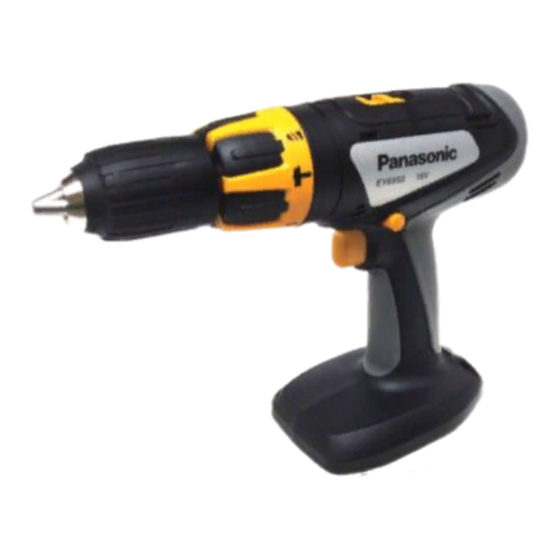
ORDER NO.PTD0310U37C1 Cordless Hammer Drill Driver EY6950-U1 SPECIFICATIONS CONTENTS Page Page 1 SCHEMATIC DIAGRAM 4 TROUBLESHOOTING GUIDE 2 WIRING CONNECTION DIAGRAM 5 EXPLODED VIEW 3 DISASSEMBLY/ASSEMBLY INSTRUCTIONS 6 REPLACEMENT PARTS LIST © 2003 Matsushita Electric Works Ltd. All rights reserved. Unauthorized copying and distribution is a... -
Page 2: Schematic Diagram
EY6950-U1 1 SCHEMATIC DIAGRAM 2 WIRING CONNECTION DIAGRAM... -
Page 3: Disassembly/Assembly Instructions
EY6950-U1 3 DISASSEMBLY/ASSEMBLY INSTRUCTIONS IHOW TO DISASSEMBLE KEYLESS CHUCK. Ref. No. 1A Procedure 1A Removal of the Keyless Drill Chuck. 1. Set the clutch handle to position 1 and select "LOW" position. 2. Turn the lock collar counterclockwise direction to open the chuck jaws. - Page 4 EY6950-U1 IHOW TO DISASSEMBLE MAIN UNIT. Ref. No. 2A Procedure 2A Removal of the Housing. 1. Remove the side handle. (See Fig. 4) 2. Remove nine housing screws. (See Fig. 5) NOTE : Grease rubbing part of housing with Shell Alvania for assembly.
- Page 5 EY6950-U1 Ref. No. 2C Procedure 2A → → → → 2B → → → → 2C Removal or attachment of the Gear Box Block. (Removal) 1. Turn the thrust plate to remove. 2. The internal parts of gear box block can be removed one after another.
- Page 6 EY6950-U1 Ref. No. 2D Procedure 2D Assembly of the Adjusting Screw and the Clutch Handle. 1. Hold the driving block with the click spring on top, and align the smallest projection of adjusting screw with the clutch case at 5 o´clock position.
-
Page 7: Troubleshooting Guide
EY6950-U1 4 TROUBLESHOOTING GUIDE (Refer to WIRING CONNECTION DIAGRAM) < TROUBLE > < CHECK > < REMEDY > Does not operate. <CHECK BATTERY PACK.> NO Replace battery pack. → If no less than 18V DC is available across the (+) and (-) terminals, →... - Page 8 EY6950-U1 < TROUBLE > < CHECK > < REMEDY > Does not vibrate. <CHECK CLUTCH HANDLE.> Replace clutch (When setting clutch → Check the condition of inside of clutch handle if two projections were → handle. handle to broken or not.
-
Page 9: Exploded View
EY6950-U1 5 EXPLODED VIEW... -
Page 10: Replacement Parts List
EY6950-U1 6 REPLACEMENT PARTS LIST NOTE: *B=only available as set *C=available individually Ref.No. Part No. Part Name & Description Remarks Per Unit WEY6950K3078 HOUSING AB SET EY6481L0177 CLICK SPRING WEY6450L6808 CHUCK FASTENING SCREW WEY6950Y3228 CLUTCH HANDLE WEY6450L0638 ADJUSTING SCREW WEY6450L0578...