Table of Contents
Advertisement
Quick Links
Advertisement
Table of Contents

Related Manuals for DyneSystems DS820F

Summary of Contents for DyneSystems DS820F
-
Page 1: User Manual
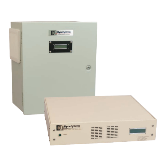
DS820F Power Amplifier Unit USER MANUAL Controller Configuration Job # ____________________ Inter-Loc V Control Model # __________________ Dyn-Loc IV Control Serial # __________________ Configuration (amps) _______ Customer-Supplied Control, 0-10 VDC www.dynesystems.com DPD-001-04B... - Page 2 From Dyne Systems, Inc. The DS820F Power Amplifier Unit (PAU) is a third generation, intelligent universal Eddy Current Power Amplifier Unit. It is an analog controller with a digital front end that offers greater flexibility for upgrading existing test cells, or for entirely new test installations. The potential applications for the PAU range from simple manual control to fully integrated closed loop installations.
-
Page 3: Table Of Contents
RACK MOUNT START-UP ....................21 INTER-LOC V START-UP ......................21 DYN-LOC IV AND CUSTOMER-SUPPLIED CONTROL START-UP ........22 SECTION 6: PREVENTIVE MAINTENANCE WALL MOUNT ........................23 RACK MOUNT ........................23 Dyne Systems • DS820F PAU Table of Contents DPD-001-04B • © Copyright Dyne Systems, Inc. - Page 4 50HZ / 60HZ OPERATION ....................24 LOW INDUCTANCE COIL.....................24 LOW MAX CURRENT ......................24 0-20MA COMMAND SOURCE .....................24 ADDITIONAL SAFETIES ......................25 DS820F CONTROL BOARD JUMPER DEFINITIONS ............25 SECTION 8: FAULTS /TROUBLESHOOTING WALL MOUNT AND RACK MOUNT TROUBLESHOOTING GUIDE ........26 WALL MOUNT SIGNALS ......................28 RACK MOUNT SIGNALS .....................30...
-
Page 5: General Information
Locate the model and serial numbers on the PAU and verify that they are the same as that shown on the cover of this manual. This information should be used when contacting DS customer support. Dyne Systems • DS820F PAU General Information DPD-001-04B • © Copyright Dyne Systems, Inc. -
Page 6: Configuration
SECTION 2: CONFIGURATION Dyne Systems • DS820F PAU Configuration DPD-001-04B • © Copyright Dyne Systems, Inc. - Page 7 CONFIGURATION (CONTINUED) Dyne Systems • DS820F PAU Configuration DPD-001-04B • © Copyright Dyne Systems, Inc.
- Page 8 CONFIGURATION (CONTINUED) Dyne Systems • DS820F PAU Configuration DPD-001-04B • © Copyright Dyne Systems, Inc.
-
Page 9: Modes Of Reset Operation
If the customer does not specify the mode of operation at the time of order, it will be set to the Reset Required Mode. Dyne Systems • DS820F PAU Configuration DPD-001-04B • © Copyright Dyne Systems, Inc. -
Page 10: Installation Environment
The atmosphere should be free of corrosive gases, vapors or particulates that could cause fire or explosion. Relative humidity should be 0 to 95% non-condensing. Temperature range should be 32 to 90° F (0 to 32.2° C). Dyne Systems • DS820F PAU Installation Environment DPD-001-04B • © Copyright Dyne Systems, Inc. -
Page 11: Transformer Compatibility
50 amp 13,850 UEC-PAU-50-W02 50 amp 12,000 50 amp 13,850 UEC-PAU-50-W03 50 amp 12,000 UEC-PAU-50-W03 50 amp 13,850 UEC-PAU-50-W04 50 amp 24,000 UEC-PAU-100-W01 100 amp 24,000 Dyne Systems • DS820F PAU Transformer Compatibility DPD-001-04B • © Copyright Dyne Systems, Inc. -
Page 12: Rack Mount Pau, Coil And Transformer Compatibility Table
UEC-PAU-15-R01 15 amp 3,600 15 amp 4,155 15 amp 3,600 15 amp 4,155 UEC-PAU-30-R01 30 amp 7,200 30 amp 8,310 30 amp 7,200 30 amp 8,310 Dyne Systems • DS820F PAU Transformer Compatibility DPD-001-04B • © Copyright Dyne Systems, Inc. -
Page 13: Installation And Start Up
INSTALLATION AND START UP WHO SHOULD INSTALL THE PAU The DS820F PAU operates as part of a system. If the system is not properly wired, equipment may be damaged. Only a qualified licensed electrician should install the DS820F PAU. All installations should comply with the most current version of the National Electric Code (NEC) as well as all local codes. -
Page 14: Wall Mount Mechanical Installation
TB1-4 and TB1-5 can be used in lieu of a PLC or controller. Close the access door and secure Dyne Systems • DS820F PAU Installation & Start Up DPD-001-04B • © Copyright Dyne Systems, Inc. -
Page 15: Wall Mount Terminal Block Connections
Wall Mount Terminal Block Connections Figure 5.2 - Wall-Mount Terminal Block Connection Figure 5.3 - Enlarged view of terminal block Dyne Systems • DS820F PAU Installation & Start Up DPD-001-04B • © Copyright Dyne Systems, Inc. -
Page 16: Wall Mount Subpanel
Wall Mount Subpanel Snubber Board SCR Bridge Heatsink Control Transformer Fuses DS820 Current Control Board Transducer Main Fuses Terminal Blocks Figure 5.4 - Wall Mount Subpanel Dyne Systems • DS820F PAU Installation & Start Up DPD-001-04B • © Copyright Dyne Systems, Inc. -
Page 17: Wall Mount Start-Up
Step 3. Perform the Max Current adjustment if this is the first time use. (See Appendix A, p. 32 for setting Max Current.) Your DS820F PAU is ready for use. Dyne Systems • DS820F PAU Installation & Start Up... -
Page 18: Dyn-Loc Iv And Customer-Supplied Control Start-Up
Step 3. Perform the Max Current adjustment if this is the first time use. (See Appendix A, p.32 for setting Max Current.) Your DS820F PAU is ready for use. Dyne Systems • DS820F PAU Installation & Start Up... -
Page 19: Rack Mount Installation
RACK MOUNT INSTALLATION Enclosure Specification The DS820F PAU enclosure for the rack style PAU is designed for use in areas which do not require oil-tight and dust-tight applications. Fans are used to cool the interior. The intake is at the front of the unit. -
Page 20: Rack Mount Mechanical Installation
When connections are secure, the PAU should be in position and mounted to the rack. Rack Mount Wiring Figure 5.6 - 15 Amp Rack Mount PAU Back Panel Connections Dyne Systems • DS820F PAU Installation & Start Up DPD-001-04B • © Copyright Dyne Systems, Inc. - Page 21 RACK MOUNT WIRING (CONTINUED) Figure 5.7 - 30 Amp Rack Mount PAU Back Panel Connections Dyne Systems • DS820F PAU Installation & Start Up DPD-001-04B • © Copyright Dyne Systems, Inc.
-
Page 22: Rack Mount Start-Up
Step 3. Perform the Max Current adjustment if this is the first time use. (See Appendix A, p.32 for setting Max Current.) Your DS820F PAU is ready for use. Dyne Systems • DS820F PAU Installation & Start Up... -
Page 23: Dyn-Loc Iv And Customer-Supplied Control Start-Up
Step 3. Perform the Max Current adjustment if this is the first time use. (See Appendix A, p.32 for setting Max Current.) Your DS820F PAU is ready for use. Dyne Systems • DS820F PAU Installation & Start Up... -
Page 24: Preventive Maintenance
The only maintenance items on the rack mount PAU are the air vents and cooling fan(s). It is recommended that the air vents and cooling fans(s) be inspected monthly and any dust or debris be removed. Dyne Systems • DS820F PAU Preventive Maintenance DPD-001-04B • © Copyright Dyne Systems, Inc. -
Page 25: Application Specific Functionality
Current Feedback This feedback signal is a representation of the output current as seen by the current control loop within the DS820F circuit board. The signal is buffered and is available at TB15 on the DS820F circuit board. Note: This signal is used for troubleshooting. Please reference Appendix D for more information. -
Page 26: Additional Safeties
“GP Input Fault 1, 2 or 3” . This message can be customized at the factory if desired. The DS820F ships with jumpers in these inputs. Note: Reference Table 7 .1 (next page) for all jumper definitions. -
Page 27: Faults /Troubleshooting
NOTE: The main circuit board for the PAU has two LEDs (see Figure A.1, page 33 - DS820F Main Circuit Board). The LED toward the center of the board will pulse once each second. If the LED is not blinking the circuit board is defective or it is not getting power. - Page 28 - 109% for approximately 10 seconds, 110% (or greater) are seconds, 110% (or greater) are not allowed. not allowed. Table 8.1 - Wall and Rack Mount Troubleshooting Guide Dyne Systems • DS820F PAU Faults/Troubleshooting DPD-001-04B • © Copyright Dyne Systems, Inc.
-
Page 29: Wall Mount Signals
Coolant Temp Input: Coolant temperature switch TB5-1 Analog Out (+) Output: Voltage proportional to coil current (0 - 10VDC) TB5-2 Analog Out (-) Output: Common Continued next page Dyne Systems • DS820F PAU Faults/Troubleshooting DPD-001-04B • © Copyright Dyne Systems, Inc. - Page 30 Input: Connection to facility main power Ground Input: Connection to facility main ground Table 8.2 - Faults / Troubleshooting, Wall Mount Signals Note: For further troubleshooting assistance, please contact Dyne Systems. Dyne Systems • DS820F PAU Faults/Troubleshooting DPD-001-04B • © Copyright Dyne Systems, Inc.
-
Page 31: Rack Mount Signals
Faults/Troubleshooting (Continued) RACK MOUNT SIGNALS The DS820F Rack Mount Unit uses D-SUB and MS type connections on the rear panel to interface to the rest of the system. A qualified electrician can use the table below to monitor inputs / outputs to aid in diagnosing problems. -
Page 32: Customer Support
Note: For further troubleshooting assistance, please contact Dyne Systems. SECTION 9: CUSTOMER SUPPORT Dyne Systems Customer Support can be reached at 1-800-657-0726 or by Email at sales@dynesystems.com. Please have the serial and model numbers available for all products. Dyne Systems • DS820F PAU Troubleshooting - Customer Support... -
Page 33: Product Warranty
Buyer’s equipment for a particular purpose. Repair or configuration of Buyer-supplied equipment will be charged at Dyne Systems normal rate. Dyne Systems • DS820F PAU Troubleshooting - Customer Support DPD-001-04B • © Copyright Dyne Systems, Inc. -
Page 34: Appendix A: Pau Max Current Adjustment
PAU needs to be adjusted to match the characteristics of the dynamometer coil. The DS820F PAU has a Max Current adjustment potentiometer (P3). Since dynamometer coil characteristics vary greatly depending on many factors, it is difficult to preset this adjustment at the factory. - Page 35 Connect a DMM to TP20 (black lead) and TP6 (red lead). Adjust P4 until you measure -0.050VDC (negative 50mV). Max current setting is complete LEDs TP20 Figure A.1 - DS820F Main Circuit Board Dyne Systems • DS820F PAU Appendix A - Max Current Adjustment DPD-001-04B • © Copyright Dyne Systems, Inc.
-
Page 36: Appendix B: Ohm's Law
(P) Power is the amount of current times the voltage level at a given point measured in wattage or watts. Dyne Systems • DS820F PAU Appendix A - Max Current Adjustment DPD-001-04B • © Copyright Dyne Systems, Inc. -
Page 37: Appendix C: Drawings And Schematics
APPENDIX C: DRAWINGS AND SCHEMATICS RACK MOUNT CONNECTIONS - 15 AMP Figure C-1 - Rack Mount Connections, 15 Amp Dyne Systems • DS820F PAU Appendix B - Ohm's Law DPD-001-04B • © Copyright Dyne Systems, Inc. -
Page 38: Rack Mount Connections - 30 Amp
RACK MOUNT CONNECTIONS - 30 AMP Figure C-2 - Rack Mount Connections, 30 AMP Dyne Systems • DS820F PAU Appendix C - Drawings & Schematics DPD-001-04B • © Copyright Dyne Systems, Inc. -
Page 39: Wall Mount Schematic
WALL MOUNT SCHEMATIC Figure C-3 - Wall Mount Schematic Dyne Systems • DS820F PAU Appendix C - Drawings & Schematics DPD-001-04B • © Copyright Dyne Systems, Inc. -
Page 40: Appendix D: Current Module Required Conductor Definition
Feedback Resistor (R36): 150 Ohms Required Number of Conductors: PAU Max Current Rating Expected Voltage Across FB Resistor @ Max Current (V) 33.33 5.00 11.11 5.00 Dyne Systems • DS820F PAU Appendix D - Required Conductor Definition DPD-001-04B • © Copyright Dyne Systems, Inc. -
Page 41: Appendix E: Acronyms
VAC – Volts Alternating Current JB – Junction Box VDC – Volts Direct Current KVA – Kilovolt-Ampere XFMR – Transformer KW – Kilowatt LBS – Pounds Dyne Systems • DS820F PAU Appendix E - Acronyms DPD-001-04B • © Copyright Dyne Systems, Inc.
Need help?
Do you have a question about the DS820F and is the answer not in the manual?
Questions and answers