Summary of Contents for JBL Control 24C/CT Micro
- Page 1 Control Contractor Ceiling Loudspeakers Control 24C/CT Micro and Control 24CT MicroPlus Owner's Manual...
-
Page 2: Table Of Contents
Product Feature Identification Installation Preparations Step-By-Step Installation and Wiring Painting the Speaker Maintenance Contacting JBL Thank you for purchasing JBL Control Contractor ceiling loudspeakers. Read through this manual to familiarize yourself with the features, applications and precautions before you use these products. -
Page 3: Product Description
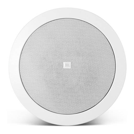
The JBL Control Contractor ceiling loudspeakers utilize innovative design and materials to provide premium level performance from compact in-ceiling speakers. CONTROL 24C MICRO - Most compact of the JBL ceiling speakers, the Control 24C Micro contains a 4" woofer and a ¾" titanium-coated tweeter, providing high-fidelity sound over an extremely wide coverage area. -
Page 4: Product Feature Identification
Product Feature Identification (Control 24CT Micro Shown) Attachment Screw Tweeter Tuning Port Rotating Mounting Woofer Seismic Tab (Secondary Support) Steel Backcan Attachment points for included or Connector installer-provided Block strain-relief fittings. Strain Relief... -
Page 5: Installation Preparations
A pre-installation bracket can also function as a cutout template when many cutouts are to be made. Two types of pre-installation brackets are available from JBL Professional as optional accessories: 1) The optional NEW-CONSTRUCTION BRACKET is made of flat sheet metal, with wings to attach to the building structure. - Page 6 The speakers are packaged in cardboard cutout templates which can be used for scribing the cutout hole onto your ceiling surface. The cutout size for the Control 24C/CT Micro and the Control 24CT MicroPlus is the same as the Regular Control 24C & CT.
-
Page 7: Step-By-Step Installation And Wiring
Step-by-Step Installation and Wiring The installation system has been designed so that the entire installation can be accom- plished from beneath the ceiling, for instances when access above the tile is not possible or practical. However, in some cases it may be easier with removable ceiling tiles to access from both the top and bottom of the ceiling tile during various phases of the installation. - Page 8 Step 3 - Connect the Wiring to the Input Terminal Block. Connect the wiring to the UL & CE-rated, touch-proof terminal block that is attached to the side of the speaker by stripping the insulation back about about the bare end of wire into the connector and screwing the hold-down screw until tight using a small flat blade screwdriver.
- Page 9 Step 4 - Add included metal strain relief as necessary. The Control 24C/CT Micro and the 24CT MicroPlus are equipped with two locations where the installer can affix strain relief con- nectors - one is on the back of backcan and one is on the side (for applications with shallow access).
- Page 10 1 - Cable Tie - If using loose wire, this cable tie can secure the loose ends of wire that are connected to the terminal block. The strap can be tightened by pulling on the loose end and then tightening the holding screw. 2 - Adjustable Metal Strap - This adjustable steel tie fitting is provided for those applica- tions where it can be utilized to affix a set of wires.
- Page 11 Step 6 - Connect a Secondary Support Line to Seismic Tab - A tab is provided on the side of the Control 24C/CT Micro and the Control 24CT MicroPlus for connection to an inde- pendent secondary support point. Some construction codes require using this secondary sup- port point, by connecting a support line to a separate secure support point.
-
Page 12: Painting The Speaker
The rim can be painted before installation or in cases where the rim needs to be finished along with the ceiling, the speaker rim can be painted after attaching into the ceiling. Type of Paint - The speaker's polystyrene rim accepts almost any type of latex or oil based paint. Two coats are recommended. -
Page 13: Maintenance
These products are in compliance with the EMC Directive 89/336/EEC and Article 10 (1) of the directive. In compliance with Technical Regulations EN50081-1 and EN50082-1. For a copy of the model-specific CE Declaration of Conformity, contact JBL at the address listed at the end of this manual. -
Page 15: Contacting Jbl
Warranty & Contacting JBL These products are designed and backed by JBL Professional, the world leader in sound rein- forcement. For complete JBL warranty information, to order replacement parts or to ask for clarifications to this manual, contact JBL Professional. - Page 16 JBL Professional 8500 Balboa Blvd, P.O. Box 2200 Northridge, CA 91329 U.S.A. A Harman International Company MAN_C24MICRO Revision D...


Need help?
Do you have a question about the Control 24C/CT Micro and is the answer not in the manual?
Questions and answers