
Related Manuals for Sony Vaio PCG-FH120


Summary of Contents for Sony Vaio PCG-FH120
-
Page 1: Service Manual
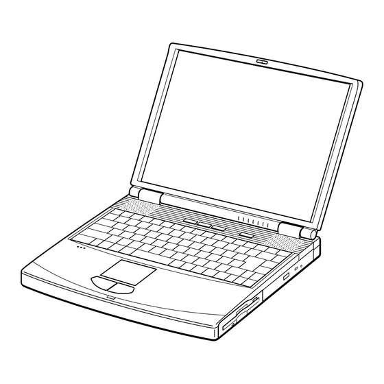
PCG-FX120/FX140/FX150/FX170/FX190 SERVICE MANUAL US Model Canadian Model S400 Illust : PCG-FX170 NOTEBOOK COMPUTER 9-872-179-11... - Page 2 Caution Markings for Lithium/Ion Battery - The following or similar texts shall be provided on battery pack of equipment or in both the Sony and VAIO are trademarks of Sony. Intel logo and Intel Inside operating and the service instructions.
-
Page 3: Table Of Contents
TABLE OF CONTENTS Section Title Page Section Title Page CHAPTER 1. REMOVAL CHAPTER 2. SELF DIAGNOSTICS 1-1. Flowchart ................. 1-1 2-1. Required Tools and Peripheral Devices ......2-1 1-2. Main Electrical Parts Location Diagram ......1-1 2-2. Tools and Peripheral Device Connection ......2-3 1-3. -
Page 4: Chapter 1. Removal
CHAPTER 1. REMOVAL 1-1. Flowchart BEZEL DISPLAY INVERTER HOUSING HOUSING UNIT ASSY ASSY ASSY ∗P 1-7 ∗P 1-7 ∗P 1-8 ∗P 1-8 (P 1-9) (P 1-9) (P 1-10) (P 1-10) 〈 P 1-11 〉 〈 P 1-12 〉 〈 P 1-12 〉 〈... -
Page 5: Hinge Cover
1-3.Removal 1. Hinge Cover 2Hinge Cover 1Door I/O 2Hinge Cover 2. Keyboard Unit, Palm Rest Assy, Hood Keyboard Assy, Touch Pad, CNX-125 Board 1M2X4 Special Head (Black) 2Pull it up sliding it 4M2X4 Special Head (Black) to the right. 6Keyboard Unit 3Hood Keyboard Assy 9Pull it to the front slightly and raise to remove it. -
Page 6: Display Assy, Dvd-Rom Drive, Combination Drive Bay (Cd-Rw/Dvd-Rom)
3. Display Assy, DVD-ROM Drive, Combination Drive (CD-RW/DVD-ROM) 5Plate Ground 4+B M2 (X2) (Gold) 7M2X6 Display Assy Special Head (Gold) 4+B 2X12 (Black) 8M2X6 Special Head (Black) 6M2.6 Cross (Hole) Bind (Black) 6M2.6 Cross (Hole) Bind (Black) 1Screw (M2), 0 Number P3 Kind (Black) 6M2.6 Cross (Hole) Bind (X2) (Black) DVD-ROM Drive... -
Page 7: Latch Detector, Pws-13 Board
5. Latch Detector, PWS-13 Board 1M2X4 Special Head (X2) (Black) 4PWS-13 Board 2Latch Detector MBX-49 Board CN2701 6. PC Card Connector, Modem Card, MBX-49 Board, Lithium Battery 1M2X4 Special Head (X2) (Black) qjI/O Bracket qhScrew (HEX) (X6) (Silevr) 2M2X4 Special Head (X5) (Black) CPU * 9PC Card Connector... -
Page 8: Speaker Unit, Swx-73 Board
7. Speaker Unit, SWX-73 Board 3M2X4 (X2) (Black) 2M2X4 (X7) (Black) SWX-73 Board 4Speaker Unit CN301 SWX-73 Board CN302 5SWX-73 Board 3M2X4 (X2) (Black) SWX-73 Board CN303 4Speaker Unit 6Hood Keyboard 8. SO-DIMM 1M2X4 Special Head (Black) 2DIMM Door Removal of SO-DIMM a →... -
Page 9: Modem Card
9. Modem Card 1M2X4 Special Head (Black) 2Modem Door 3M2 Grip (X2) (Black) 4Modem Card Confidential PCG-FX120/FX140/FX150/FX170/FX190 (UC) -
Page 10: Lcd Section (Fx190 Model) - Made By Sa
10. LCD Section (FX190 Model) – Made by SA – 1. Bezel Housing Assy, LCD Unit (15 inch) 1Side (15) Screw Cover (X3) (Gold) 3Cover Screw 2+P M2X3 (X3) Shaft Bezel Housing Assy 4+P 2.6X6 Lock Precision Type3 (Black) : claw part 3Cover Screw 2+P M2X3 (X3) (Gold) Shaft... -
Page 11: Inverter Assy, Lcd Harness, Fpc, Display Housing Assy
2. Inverter Assy, LCD Harness, FPC, Display Housing Assy 6Shield Tape (SK) 8LCD Harness 7M2X4 Special Head (Black) Inverter Assy 2Inverter Assy 4FPC 9Display Housing Assy Confidential PCG-FX120/FX140/FX150/FX170/FX190 (UC) -
Page 12: Lcd Section (Fx150/Fx170 Model) - Made By Sa
11. LCD Section (FX150/FX170 Model) – Made by SA – 1. Bezel Housing Assy, LCD Unit (15 inch) 1Side (15) Screw Cover (X3) (Gold) 3Cover Screw 2+P M2X3 (X3) Shaft Bezel Housing Assy 4+P 2.6X6 Lock Precision Type3 (Black) : claw part 3Cover Screw 2+P M2X3 (X3) (Gold) Shaft... - Page 13 2. Inverter Assy, FPC, Display Housing Assy 6Shield Tape (SK) 8LCD Harness 7M2X4 Special Head (Black) Inverter Assy 2Inverter Assy 4FPC 9Display Housing Assy Confidential PCG-FX120/FX140/FX150/FX170/FX190 (UC) 1-10...
-
Page 14: Lcd Section (Fx140 Model) - Made By Sa
12. LCD Section (FX140 Model) – Made by SA– 1. Bezel Housing Assy 1Cover Screw Lower 2M2X4 Special : claw part Head (X2) (Black) 1Cover Screw Upper 2M2X4 Special Head (X2) (Black) Bezel Housing Assy 4M2X4 Special Head (X5) (Black) 4M2X4 Special Head (X5) (Black) How to release the claw a LCD Unit... -
Page 15: Bracket Lcd Left, Bracket Lcd Right, Lcd Unit (14 Inch)
2. Bracket LCD Left, Bracket LCD Right, LCD Unit (14 inch) 3+P M2x3 Lock (X4) (Black) 5LCD Unit 1+P M2x3 Lock (X4) (Black) 4Bracket LCD Left 2Bracket LCD Right 3. FPC, Inverter Assy, Display Housing Assy, LCD Harness 8Shield Tape (SK) 0LCD Harness 6M2X4 Special Head (Black) -
Page 16: Lcd Section (Fx120 Model) - Made By Ac
13. LCD Section (FX120 Model) – Made by AC– 1. Bezel Housing Assy 1Lower Screw Cover (x2) 2M2X4 Bezel Housing Assy Special Head (X2) : claw part (Black) 1Upper Screw Cover (x2) 2M2X4 Special Head (X2) (Black) 4M2X4 Special Head (X5) (Black) How to release the claw A. -
Page 17: Bracket Lcd Left, Bracket Lcd Right, Lcd Unit (13 Inch)
2. Bracket LCD Left, Bracket LCD Right, LCD Unit (13 inch) 1+PS M2x3 (X3) (Black) 5LCD Unit 1+PS M2X3 (X3) (Black) 4Bracket LCD Left 2Bracket LCD Right 3. FPC, Inverter Assy, Display Housing Assy, LCD Harness, 8Shield Tape (SK) 9M2X4 0LCD Harness Special Head (Black) Inverter Assy... -
Page 18: Replacing The Cpu
1-4.Replacing the CPU NOTE: This computer uses either one of the two types of CPU socket. The CPU locking position and the lock-release position are different depending on the types of the CPU socket. 1. Removing the CPU 1 Insert a flat-blade screwdriver into the notch as shown in the illustration and rotate it so that the protrusion comes to the lock release position. -
Page 19: Dip Switch Setting Of The Mbx-49 Board
1-5. DIP Switch Setting of the MBX-49 Board The DIP switch on the MBX-49 board (main board) is set to match with the LCD that is used in this computer, because several types of LCD are used as shown in the following table and the DIP switch setting differs depending on the LCD type. - Page 20 MODEL Name of LCD Part No. DIP switch setting Note FX140 1-418-716-21 Main The upper position where ON indication is shown is the ON position . The lower position is the OFF position. 1 2 3 4 5 6 7 8 0 0 1 1 1 1 1 1 ON/OFF 0 : ON...
-
Page 21: Chapter 2. Self Diagnostics
CHAPTER 2. SELF DIAGNOSTICS 2-1. Required Tools and Peripheral Devices Tools and Peripheral Devices Test Items Serial Loopback Tool Serial Port (COM) test Specified Loopback Tool (Refer to next page.) Parallel Loopback Tool Parallel Port (printer) test Specified Loopback Tool (Refer to next page) Stereo microphone Audio related tests Headphone... - Page 22 [Reference] On Serial/Parallel Loopback Tool • The serial loopback tool and the parallel loopback tool are necessary for diagnostics of the serial communication line and the parallel communication line. Fabricate the serial loopback tool and the parallel loopback tool locally referring to the connection diagrams shown below.
-
Page 23: Tools And Peripheral Device Connection
2-2. Tools and Peripheral Device Connection System Connection Diagram 7VAIO for IEEE1394 test Serial I/F Modem 5Transmission 9Combination Drive line simulator Headphones (CD-RW/DVD-ROM) connector DVD-ROM 4Headphones Power SW Phone jack 3Stereo microphone MIC IN qgHDD qsDiagnostics CD-ROM media 6PC card tester qaDiagnostics FD media qdBattery... -
Page 24: Starting Up The Service Diagnostics
2-3. Starting up the Service Diagnostics 1. The service diagnostics floppy disk and CD disc are prepared for the respective models separately. Insert the service diagnostics floppy disk and CD disc of the desired model, then turn on the main power of the personal computer. Reads automatically the model information stored in the CD-ROM and displays the test menu. - Page 25 • HDD test... Tests whether the HDD returns a response when communication is established with the hard disk drive. The HDD can be tested without damaging the HDD data (without formatting the HDD) in this test since the HDD data is tentatively stored in memory during the test.
- Page 26 • Touch pad test... Tests the touch pad. Tests whether the cursor moves, and whether right-clicking and left-clicking function properly. The dialog box appears three times. Move the cursor to the box that appears. The tests are performed in the following order. (1) Touch pad (2) Left-click button (3) Right-click button (Two times)
-
Page 27: Inspecting Windows
• IrDA test... The computer cannot perform this test. • Jog dial test... The computer cannot perform this test. • Short aging test.../Long aging test... Performs the aging test. The short aging test ends when all test items have been performed once. The long aging test checks the machine for about 10 hours by repeating the test items. -
Page 28: Self Diagnostics Change History
• Video NOTE: Because this test is performed by visual inspection, confirm first the normal video patterns using a com puter known to be good, before starting the test. In this test, several video patterns are output from the PC and shown on the monitor display. When all the video patterns are displayed correctly, the PC under testing is judged to be normal. -
Page 29: Chapter 3. Block Diagram
CHAPTER 3. BLOCK DIAGRAM PCG-FX Series µ-PGA2 Connector TV-OUT BLOCK DIAGRAM Rev. 1.00 SMBUS2 mini Jack FW82801 w/ Port Replicator (PCGA-PRFX1) 10/10/00 Selector MP III 850/800/ 750/700 MHz Memory Subsystem 50pin CN (Cache:256kB OD) DSub-15 (LED Signal Include) PC100 SO-DIMM Encoder CH7007A Port Replicator... -
Page 30: Chapter 4. Frame Harness Diagram
CHAPTER 4. FRAME HARNESS DIAGRAM DC-IN NETWORK MONITOR PRINTER SERIAL PHONE Rear Panel KEY BOARD INVERTER DC FAN FFC LED CNX-123 Board CN702 CN2801 CN1101 CN1801 CN105 CN103 CN152 CN3001 CN1502 (Side-A) CN1902 CN2004 CN2602 CN701 CN1401 VIDEO OUT CN802 CN2201 (FX150/FX170/FX190 Model Only) CN1701... -
Page 31: Chapter 5. Exploded Views And Parts List
CHAPTER 5. EXPLODED VIEWS AND PARTS LIST NOTE: The components identified by mark 0 or • The mechanical parts with no reference number in the dotted line with mark 0 are critical for safety. exploded views are not supplied. Replace only with part number specified. •... -
Page 32: Main Section
5-1. Main Section Ref.No. Part No. Description Ref.No. Part No. Description X-4623-411-1 (FX150/FX170/FX190)... 8-749-019-29 (FX140/FX150/FX170/FX190)... ASSY BOTTOM (AM) IC MC-4516CD641PS-A80 X-4623-412-1 (FX120/FX140)...ASSY BOTTOM (BM) (PC-100 SO-DIMM (128MB CL2)) 4-640-837-22 DOOR BATTERY 8-749-019-00 (FX140/FX150/FX170/FX190)... 4-651-706-01 HEATSINK BOTTOM IC HYM71V16M655AT6-P * 11 4-651-707-01 INSULATOR HEATSINK BOTTOM (PC-100 SO-DIMM (128MB CL2)) 1-960-827-21 HARNESS (2 PIN) - Page 33 ∗ ∗ (FX120/FX140/ FX150 Model) (FX170 FX190 Model) 701 (Refer to Page 5-12.) ∗1 The VIDEO OUT connector is mounted only in FX150/FX170/FX190 Model. ∗2 For the destination of the cable, refer to pages 5-5, 5-7 and 5-9. Confidential PCG-FX120/FX140/FX150/FX170/FX190 (UC)
-
Page 34: Lcd Section (Fx190 Model) - Made By Sa
5-2. LCD Section (FX190 Model) – Made by SA – Ref.No. Part No. Description Ref.No. Part No. Description 1-476-316-11 INVERTER UNIT 4-641-726-11 SCREW (M2), SPECIAL HEAD X-4623-380-1 HINGE LEFT 15 4-642-761-01 +P M2X3 LOCK X-4623-446-2 ASSY HOU, BEZEL 15SA-Z (EXP) 4-644-165-01 SCREW (M2.6X4), 0 PLATE P1 MAIN 4-637-902-41 LATCH 4-643-550-01 +P 2.6X6 LOCK PRECISION TYPE3... -
Page 35: Lcd Section (Fx150/Fx170 Model) - Made By Sa
5-3. LCD Section (FX150/FX170 Model) – Made by SA – Ref.No. Part No. Description Ref.No. Part No. Description 1-476-316-11 INVERTER UNIT 4-641-726-11 SCREW (M2), SPECIAL HEAD X-4623-380-1 HINGE LEFT 15 4-642-761-01 +P M2X3 LOCK X-4623-446-2 ASSY HOU, BEZEL 15SA-Z (EXP) 4-644-165-01 SCREW (M2.6X4), 0 PLATE P1 MAIN 4-637-902-41 LATCH 4-643-550-01 +P 2.6X6 LOCK PRECISION TYPE3... -
Page 36: Lcd Section (Fx140 Model) - Made By Sa
5-4. LCD Section (FX140 Model) – Made by SA – Ref.No. Part No. Description Ref.No. Part No. Description 1-476-316-11 INVERTER UNIT 4-641-726-11 SCREW (M2), SPECIAL HEAD X-4623-378-1 HINGE LEFT MV 7-628-254-00 SCREW +PS 2.6X5 X-4623-445-2 ASSY HOU, BEZEL 14SA-Z (EXP) 4-642-761-01 +P M2X3 LOCK 4-635-277-22 COVER SCREW LOWER 4-635-276-22 COVER SCREW UPPER... -
Page 37: Lcd Section (Fx120 Model) - Made By Ac
5-5. LCD Section (FX120 Model) – Made by AC – Ref.No. Part No. Description Ref.No. Part No. Description ACCESSORIES 1-476-316-11 INVERTER UNIT X-4623-378-1 HINGE LEFT MV ************ X-4623-444-2 ASSY HOU, BEZEL 13.3M (EXP) A-8048-965-A ASSY WEIGHT SAVER (Z) 4-635-277-22 COVER SCREW LOWER 4-635-276-22 COVER SCREW UPPER (Refer to Page 5-4.) 0702... - Page 39 VAIO® Notebook Quick Start PCG-FX120/FX120K, PCG-FX140/FX140K PCG-FX150/FX150K, PCG-FX170/FX170K PCG-FX190/FX190K...
- Page 40 Contents Notice to Users ..................3 Owner’s Record ....................4 Safety Information ..................4 Regulatory Information .................6 Disposal of Lithium Ion Battery ..............8 Industry Canada Notice .................8 Welcome ....................11 Features .......................11 Unpacking Your Notebook .................12 Setting Up Your VAIO® Notebook ............15 Locating Controls and Connectors ..............15 Connecting a Power Source ................20 Starting Your Notebook ................24 Registering Your Notebook ................25...
- Page 41 VAIO Notebook User Guide...
-
Page 42: Notice To Users
It is an Sony Electronics Inc. reserves the right to make open system in which business proprietors can any modification to this manual or the participate voluntarily. -
Page 43: Owner's Record
Never install modem or telephone or disassembly is prohibited. wiring during a lightning storm. i.LINK is a trademark of Sony used only to Never install telephone jacks in wet designate that a product contains an IEEE 1394 locations unless the jack is connection. - Page 44 Sony Customer Information Service Center l’interface réseau. at 12451 Gateway Blvd., Ft. Myers, FL 33913 Soyez très prudent lorsque vous or find Sony Customer Service on the web at: installez ou modifiez les lignes http://www.sony.com/pcsupport. téléphoniques. Évitez d’utiliser le modem durant un...
-
Page 45: Regulatory Information
PCG-954A Consult the dealer or an experienced PCG-955A radio/TV technician for help. Responsible Party: Sony Electronics Inc. You are cautioned that any changes or modifications not expressly approved in this Address: 1 Sony Drive manual could void your authority to operate this Park Ridge, NJ 07656 equipment. -
Page 46: Regulatory Information
Terrasses de la Chaudiére, Tour centrale at 12451 Gateway Blvd., Ft. Myers, FL 33913 1 promenade du Portage, 5 étage Hull or find Sony Customer Service on the web at: PQ K1A 0N2. http://www.sony.com/pcsupport This Class B digital apparatus complies with Repair of this equipment should be made only Canadian ICES-003. -
Page 47: Disposal Of Lithium Ion Battery
You can return your unwanted lithium ion mistreated. Do not batteries to your nearest Sony Service Center or disassemble, heat above 212°F Factory Service Center. (100°C) or incinerate. Dispose of used battery In some areas the disposal of lithium promptly. - Page 48 Industry Canada Notice Repairs to certified equipment should be télécommunication. Le matériel doit également coordinated by a representative designated by être installé en suivant une méthode acceptée de the supplier. Equipment malfunctions or any raccordement. L’abonné ne doit pas oublier repairs or alterations made by the user to this qu’il est possible que la conformité...
- Page 49 VAIO® Notebook Quick Start...
-
Page 50: Welcome
Welcome Congratulations on your purchase of the Sony VAIO® Notebook. Sony has combined leading-edge technology in audio, video, computing, and communications to provide you with state-of-the-art personal computing. Features For a complete description of the specifications of your VAIO® Notebook, see “Specifications”... -
Page 51: Unpacking Your Notebook
VAIO® Notebook Quick Start DVD-ROM drive plays DVD-ROM, CD-ROM, CD-RW, and CD-R discs. This drive is available on select models only. Your optical drive differs depending on the model you purchase. Unpacking Your Notebook To unpack your VAIO notebook, remove the following components from the box. -
Page 52: Software Cds
Unpacking Your Notebook Manuals VAIO® Quick Start — Contains information on unpacking and setting up your notebook, supplementary updates, and software information. Microsoft® Windows® Millennium Edition Getting Started manual or the Microsoft® Windows® 2000 Professional Getting Started manual — Explains how to use the basic features of this latest Windows operating system. - Page 53 VAIO® Notebook Quick Start...
-
Page 54: Setting Up Your Vaio® Notebook
Setting Up Your VAIO® Notebook This section describes the controls and connectors on your VAIO® Notebook, how to connect your notebook to a power source, and how to start and shut down your notebook. Locating Controls and Connectors Front LCD (Liquid Crystal Display) screen Battery 1 and 2 indicators Speakers Hard disk drive indicator... - Page 55 Headphone connector Battery bay * i.LINK is a trademark of Sony used only to designate that a prodcut contains an IEEE 1394 connection. The i.LINK connection may vary, depending on the software applications, operating system, and i.LINK-compatible devices. All products with an i.LINK connection may not communicate with each other.
- Page 56 Locating Controls and Connectors Right PPK buttons Power button Optical drive (CD-RW/DVD-ROM drive for PCG-FX170/PCG-FX170K PCG-FX190/PCG-FX190K) (DVD-ROM drive for PCG-FX120/PCG-FX120K/PCG-FX140 PCG-FX140K/PCG-FX150/PCG-FX150K) Multipurpose bay...
- Page 57 VAIO® Notebook Quick Start Back Modem jack Monitor connector USB connectors Ethernet connector Serial connector DC In connector Printer connector Warning: Only connect 10BASE-T and 100BASE-TX cables to the Ethernet network port. Do not connect any other type of network cable or any telephone line. Connecting cables other than those listed above may result in an electric current overload and could cause a malfunction, excessive heat, or fire in the connector.
- Page 58 Locating Controls and Connectors Bottom Multipurpose bay RELEASE lever Reset switch Tilt stands...
-
Page 59: Connecting A Power Source
VAIO® Notebook Quick Start Connecting a Power Source You can use either AC power or a rechargeable battery pack as a power source. Using the AC Adapter Plug the cable attached to the AC adapter into the DC In connector on the notebook. - Page 60 Connecting a Power Source When the AC adapter is not in use, unplug it from the AC outlet. Use only the AC adapter supplied with your VAIO® Notebook. Using Battery Power You can use one or two battery packs as a source of power. When using two battery packs, insert the second battery pack into the multipurpose bay on the right side of the notebook.
- Page 61 VAIO® Notebook Quick Start Insert the battery pack into the battery bay on the left side of the notebook. Inserting battery pack Battery pack (supplied) Label side facing down Close the cover of the battery bay until it clicks. If the port replicator is attached to your notebook, do not attempt to insert or remove the battery pack.
- Page 62 Connecting a Power Source There are two battery indicator lights on your notebook Battery indicator lights Battery indicator lights Battery Indicator Description Indicates the status of the battery pack in the battery bay on the left side of the notebook. Indicates the status of the battery pack in the multipurpose bay on the right side of the notebook.
-
Page 63: Starting Your Notebook
VAIO® Notebook Quick Start To remove the battery pack Open the battery bay cover. Pull out the battery pack. Removing the battery pack Close the cover of the battery bay. Starting Your Notebook Slide the LCD lock lever in the direction of the arrow, and lift the cover. Opening the notebook LCD lock lever... -
Page 64: Registering Your Notebook
To increase brightness, press Fn+F5 then the up or right arrow key. Registering Your Notebook Take advantage of Sony’s commitment to quality customer support and receive these benefits by registering your notebook: Sony Customer Support — Talk to a Support Representative to troubleshoot problems you may be having with your notebook. -
Page 65: Shutting Down Your Notebook
The notebook automatically transfers your registration information using your built-in modem and a toll-free telephone number or a local number. You may sign up for Internet access with a Sony preferred Internet Service Provider. Shutting Down Your Notebook To avoid potential loss of data, follow these steps to shut down your notebook. - Page 66 Shutting Down Your Notebook Turn off any peripheral devices connected to your notebook. During a period of inactivity, you can conserve battery life by using Standby mode. See “Controlling Power Management” in the online manual VAIO® Notebook User Guide for details. If you are unable to shut down your notebook.
- Page 67 VAIO® Notebook Quick Start...
-
Page 68: About The Software On Your Notebook
About the Software on Your Notebook Your VAIO® Notebook is ready to help you work, play, learn, and communicate as soon as you turn it on. This section provides an overview of the software titles included with your notebook and software support information. Overview Adaptec Easy CD Creator™... - Page 69 6 MB web site, a member newsletter, and 24-hour technical support. * i.LINK is a trademark of Sony used to designate that a product contains an IEEE 1394 con- nection. The i.LINK connection may vary, depending on the software applications, operating system, and i.LINK-compatible devices.
- Page 70 Sony Electronics Inc. Media Bar software is your all-in-one solution for audio/video playback. Media Bar software handles all common computer multimedia formats and controls selected Sony devices. In addition to audio/video library cataloging and playlist management, Media Bar software includes digital video quality control and effects features. Media Bar software seamlessly integrates a variety of new media formats with an easy-to-use software interface.
-
Page 71: Smart Capture
This image management software displays images from your hard disk drive, a Sony digital still camera, or a Sony Mavica® camera. The images appear in a convenient light- table format, so that you can easily view the contents of an entire folder. -
Page 72: Software Support Information
Software Support Information WinDVD™ InterVideo, Inc. WinDVD is a simple-to-use DVD player combining all the features you would expect to find in a standard consumer DVD player, in addition to some very advanced functionality, such as full VCD 2.0 support, full precision video decode, a choice of user interfaces, and video display options. - Page 73 VAIO® Notebook Quick Start McAfee® VirusScan® (Network Associates, Inc.) Web site http://support.mcafee.com phone 408-988-3832 e-mail cybr@nai.com hours M-F 9AM-5PM Central Time Netscape Communicator® (Netscape Communications Corporation) Web site http://www.netscape.com/ phone 888-4SONYPC (888-476-6972) hours 7 days a week, 24 hours a day PhotoPrinter™...
-
Page 74: Sony Service Center
* Support from 1-888-4SONYPC is free of charge for 90 days after the original date of purchase. Sony Service Center For the Sony Service Center nearest you, call 1-888-4SONYPC (1-888-476-6972) or find Sony Customer Service on the Web at http://www.sony.com/pcsupport. - Page 75 VAIO® Notebook Quick Start...
-
Page 76: Troubleshooting
Troubleshooting This section describes how to solve common problems you may encounter when using your notebook. Many problems have simple solutions, so try these suggestions before you contact Sony PC Support (http://www.sony.com/ pcsupport). Troubleshooting your notebook (Windows Me only) When starting your notebook for the first time, the VAIO InitManager dialog box will appear. - Page 77 Turn off the notebook. Remove any peripheral devices connected to the notebook. Turn the notebook back on. Press the F2 key when the Sony logo appears. The BIOS setup menu screen appears. Press the directional arrow keys to select the Exit menu.
- Page 78 10 Select Yes, then press Enter. The notebook restarts. If your notebook continues to display the message “Operating system not found”, and Windows does not start, contact Sony Customer Support. My notebook stops responding or does not shut down. It is best to shut down your notebook using the Shut Down command on the Windows Start menu.
- Page 79 VAIO® Notebook Quick Start Pressing Ctrl+Alt+Delete (at the same time) or turning off the notebook with the power switch may result in data loss in files that are currently open. My notebook does not enter the power saving mode I selected. (Windows Me only) Click Start, point to Program, point to Accessories, point to System Tools, and then click System Information.
-
Page 80: Troubleshooting The Lcd Screen
Troubleshooting Close all open applications. Push and hold the power button for four seconds or longer to shut down the notebook. The sound of my notebook’s fan is too loud. Use the PowerPanel utility to change the Thermal Control Strategy setting to Quiet. -
Page 81: Troubleshooting The Mouse And Touchpad
See “Connecting an External Display” in the online manual VAIO® Notebook User Guide for details. If you are using an optional Sony USB mouse PCGA-UMS1 series, check that the mouse is plugged into the USB connector. My touchpad does not work properly. - Page 82 Troubleshooting (Windows 2000) If you cannot turn off your notebook as described in the step above, press Ctrl+Alt+Delete (at the same time) and click Shut Down on the Windows® Security screen to restart the notebook. If you cannot restart your notebook as described in the step above, press and hold the power button for more than four seconds to turn off the notebook.
- Page 83 If you are using two PC cards, use the Sony Notebook Setup utility to disable the devices you are not currently using. * i.LINK is a trademark of Sony used only to designate that a product contains an IEEE 1394 connection. The i.LINK connection may vary, depending on the software applications, oper- ating system, and i.LINK-compatible devices.
-
Page 84: Troubleshooting Software
I hear background “noise” while using Windows Media Player to play my music CDs. Sony suggests using the preinstalled Media Bar software to play audio CDs. I can not use the DVgate software. If your notebook is using the Ultimate Battery Life profile for its power saving mode, you cannot use DVgate or Smart Connect software. -
Page 85: Troubleshooting Audio
VAIO® Notebook Quick Start My modem connection is slow. Your notebook is equipped with a 56K/V.90 compatible modem. Many factors may influence modem connection speed, including telephone line noise or compatibility with telephone equipment (such as fax machines or other modems). If you think your modem is not connecting properly to other PC-based modems, fax machines, or your Internet Service Provider, check the following: Have your phone company check that your phone line is free from any line... -
Page 86: Troubleshooting The Printer
The default setting for the printer port mode is correct for most printers. If you cannot print, try changing the printer port mode. In Sony Notebook Setup, select the Printer tab. If the printer port mode is set to ECP, change it to bi-directional. - Page 88 4-653-314-11 © 2001 Sony Electronics Inc. Printed in USA...
-
Page 89: Notebook Computer
The page shown above is on "PCG-FX120/FX140/FX150/FX170/FX190 SERVICE MANUAL" NOTEBOOK COMPUTER This manual and the constituent data may not be replicated, copied nor reprinted in whole or in part without prior written authorization of Sony Corporation. English 2001B1600-1 Sony Corporation ©... - Page 90 PCG-FX120/FX140/FX150/FX170/FX190 (UC) This manual and the constituent data may not be replicated, copied nor reprinted in whole or in part without prior written authorization of Sony Corporation. Sony Corporation Printed in USA 2001A1600-1 Information Technology Company 9-872-179-11 © 2001 Sony Corporation Published by PNC Planning &...
Need help?
Do you have a question about the Vaio PCG-FH120 and is the answer not in the manual?
Questions and answers