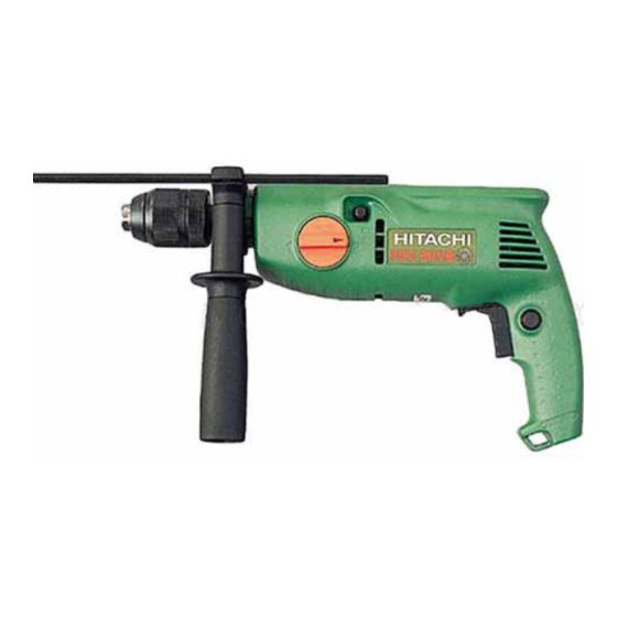
Hitachi FDV 20VB Technical Data And Service Manual
Impact drill
Hide thumbs
Also See for FDV 20VB:
- Handling instructions manual (27 pages) ,
- Handling instructions manual (14 pages)

Related Manuals for Hitachi FDV 20VB


Summary of Contents for Hitachi FDV 20VB
- Page 1 MODEL FDV 20VB POWER TOOLS TECHNICAL DATA IMPACT DRILL FDV 20VB SERVICE MANUAL LIST No. F847 Mar. 2001 SPECIFICATIONS AND PARTS ARE SUBJECT TO CHANGE FOR IMPROVEMENT...
-
Page 2: Table Of Contents
8-3. Lubrication ..........................13 8-4. Tightening Torque ........................13 8-5. Wiring Diagrams and Internal Wire Arrangements ..............13 8-6. Insulation Tests .......................... 16 8-7. No-load Current Values......................16 9. STANDARD REPAIR TIME (UNIT) SCHEDULES ..............17 Assembly Diagram for FDV 20VB... -
Page 3: Product Name
1. PRODUCT NAME Hitachi Impact Drill, Model FDV 20VB 2. MARKETING OBJECTIVE Model FDV 20VB is upgraded version of the current Model FDV 20VA. The outstanding improvements are as follows: (1) Fast drilling speed (2) Powerful motor, power input of 750 W (Subject to change by area) -
Page 4: Selling Point Descriptions
(1) Fast drilling speed Since the Model FDV 20VB is targeted for major applications of impact drills; drilling 10 mm or less diameter holes, the Model FDV 20VB achieves the fastest speed in this class. Thanks to the powerful motor and the two-step gear shift mechanism, the Model FDV 20VB overwhelms the competitors in speed when drilling small diameter holes. -
Page 5: Specifications
5. SPECIFICATIONS Model FDV 20VB Item Concrete Low speed: 20 mm (3/4")/ High speed: 13 mm (1/2") Max. capacity Steel Low speed: 13 mm (1/2")/ High speed: 8 mm (5/16") Wood Low speed: 40 mm (1-9/16")/ High speed: 25 mm (1") Mount type UNF 1/2"... -
Page 6: Comparisons With Similar Products
6. COMPARISONS WITH SIMILAR PRODUCTS 6-1. Specification Comparisons Maker HITACHI C1/C2 Item Model FDV 20VB FDV 20VA mm (") Concrete 20 (3/4) 20 (3/4) 20 (3/4) 20 (3/4) Capacity mm (") Steel 13 (1/2) 13 (1/2) 13 (1/2) 13 (1/2) mm (") -
Page 7: Drilling Speed Comparisons
The data shown below were obtained in actual factory tests, and are for reference only. Actual drilling speeds may vary in accordance with operating conditions, operator skill, etc. Drilling in concrete 1200 (47-1/4") HITACHI FDV 20VB 1000 (39-3/8") HITACHI FDV 20VA (31-1/2") (23-5/8") -
Page 8: Precautions In Sales Promotion
7. PRECAUTIONS IN SALES PROMOTION In the interest of promoting the safest and most efficient use of the Model FDV 20VB Impact Drill by all of our customers, it is very important that at the time of sales, the salesperson carefully ensures that the buyer seriously recognizes the importance of the contents of the Handling Instructions, and fully understands the meaning of the precautions listed on the Caution Plate attached to each tool. -
Page 9: Precautions In Usage
(2) Low speed and high speed changeover mechanism The Model FDV 20VB turns to the "low speed" mode by turning the shift lever until the arrow mark on the lever points "1" horizontally. The Model FDV 20VB turns to the "high speed" mode by turning the shift lever until the arrow mark on the lever points "2"... - Page 10 Lever (4) Speed control switch The FDV 20VB switch allows adjustment of the motor rotation within a range of about 25% to 60% of the full rotation speed by changing the trigger stroke. The SCR incorporated in the switch for phase control of the power supply causes heat release to rise with increasing current.
-
Page 11: Precautions In Disassembly And Reassembly
8. PRECAUTIONS IN DISASSEMBLY AND REASSEMBLY Please follow the precautions below for disassembly and reassembly procedures. The [Bold] numbers in the descriptions below correspond to the item numbers in the Parts List and exploded assembly diagram. 8-1. Disassembly 8-1-1. Removal of the Drill Chuck (1) For keyless chuck The Drill Chuck [3] (keyless chuck) is fixed to the Spindle and Gear Set [4] with a UNF 1/2"... - Page 12 8-1-2. Removal of housing (B) of Housing (A). (B) Set [19] (1) Cut the Label [31] with a cutter along the groove between the assembled Housing (A). (B) Set [19]. (2) Remove the seven Tapping Screws (W/Flange) D4 x 20 (Black) [21] and take off housing (B) of Housing (A). (B) Set [19].
-
Page 13: Reassembly
8-1-5. Disconnecting internal wires and electrical parts Disconnect the internal wires from the switch as follows. Insert the J-86 pin into the hole for the internal wire of the Speed Control Switch (2P) [25]. Press the leaf spring so that the internal wire can be disconnected, then disconnect the Internal Wires [15] [16] [17] [18] [26] [39], and the Internal Wires of the Choke Coils [26] [39] and the Noise Suppressor [37]. - Page 14 8-2-2. Reassembly of the holder When installing the Change Plate [9] and Spring (A) [8] to the Holder [10], be careful of the direction of each part. Change Plate [9] Spring (A) [8] Face the chamfered surface to the ratchet side. Ratchet Holder [10] 8-2-3.
-
Page 15: Lubrication
8-3. Lubrication 8-3-1. Application of lubricant Apply Nippeco SEP-3A (Code No. 930035) to the following portions. (1) Ratchet teeth of the Holder [10] (2) Second gear teeth, ratchet teeth, metal contacting portion and spline portion of the Spindle and Gear Set [4] (3) Gear teeth and ball bearing contacting portion of the Second Pinion [6] (4) Pinion teeth of the Armature [12] (5) Shift Arm [22] contacting portion of housing (A) - Page 16 (1) For Models with noise suppressor and choke coils (Red) (Black) Insert it with the convex side faced upward. Stop Piece Carbon brush terminal Housing (B) side Housing (A) side Connection of the carbon brush terminal and the stop piece (White) (Gray) (Black) (Brown)
- Page 17 (2) For Models without noise suppressor and choke coils (Red) (Black) Insert it with the convex side faced upward. Stop Piece Carbon brush terminal Housing (B) side Housing (A) side Connection of the carbon brush terminal and the stop piece (White) (Gray) (Black) (Brown)
-
Page 18: Insulation Tests
8-6. Insulation Tests On completion of disassembly and repair, measure the insulation resistance and dielectric strength. Insulation resistance: 7 M Ω or more with DC 500 V Megohm Tester Dielectric strength: AC 4,000 V/1 minute, with no abnormalities ......220 V --- 240 V (and 110 V for U.K. products) AC 2,500 V/1 minute, with no abnormalities ...... -
Page 19: Standard Repair Time (Unit) Schedules
9. STANDARD REPAIR TIME (UNIT) SCHEDULES Variable 60 min. MODEL Fixed Work Flow FDV 20VB General Assembly Housing (A).(B) Set Ball Bearing (608DD) Spindle and Gear Set Stator Armature Second Pinion Holder Ball Bearing (608VV) x 2 Carbon Brush Speed Control... - Page 20 F847 LIST NO. ELECTRIC TOOL PARTS LIST IMPACT DRILL 2001 • • Model FDV 20VB (E1)
- Page 21 PARTS FDV 20VB ITEM CODE NO. DESCRIPTION REMARKS USED 995-344 FLAT HD. SCREW (A) (LEFT HAND) M6X25 987-576 CHUCK WRENCH FOR 13VLB-D,13VLR-D FOR 13VLRB-D DRILL CHUCK 13VLRB-D INCLUD.2 319-546 DRILL CHUCK 13VLRE-N (W/O CHUCK WRENCH) 319-601 SPINDLE AND GEAR SET...
- Page 22 PARTS FDV 20VB ITEM CODE NO. DESCRIPTION REMARKS USED 994-273 NOISE SUPPRESSOR FOR CHN,SAF,EUROPE,OCEANIA 302-488 EARTH TERMINAL FOR NOISE SUPPRESSOR 319-613 INTERNAL WIRE (BLUE) 319-642 CHOKE COIL (BLUE) FOR CHN,SAF,EUROPE,OCEANIA 2 -- 01 * ALTERNATIVE PARTS...
-
Page 23: Standard Accessories
STANDARD ACCESSORIES FDV 20VB ITEM CODE NO. DESCRIPTION REMARKS USED 303-659 SIDE HANDLE 303-709 DEPTH GAUGE 319-616 CASE OPTIONAL ACCESSORIES ITEM CODE NO. DESCRIPTION REMARKS USED 931-851 DRILL BIT (B) D6.5X100 931-852 DRILL BIT (B) D8.0X100 931-853 DRILL BIT (B) D9.5X120 931-854 DRILL BIT (B) D10.0X120...
Need help?
Do you have a question about the FDV 20VB and is the answer not in the manual?
Questions and answers