Table of Contents
Advertisement
INSTALLATION & MAINTENANCE MANUAL
®
PRIMERA
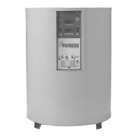
HOT WATER SUPPLY BOILER MODELS: 400B, 540B, 750B, 1000B, 1200B, 1600B & 2000B
®
PRIMERA
WATER HEATER MODELS : 400W, 540W, 750W, 1000W, 1200W, 1600W & 2000W
Installation and service must be performed by a qualified service installer, service agency or the gas supplier.
IMPORTANT: THIS MANUAL CONTAINS INFORMATION REQUIRED FOR INSTALLATION, OPERATION AND
MAINTENANCE OF THIS EQUIPMENT. READ AND FOLLOW THE INFORMATION IN THIS MANUAL AND ALL OTHER
PROVIDED INSTRUCTIONS, LABELS AND MARKINGS BEFORE INSTALLING, OPERATING OR SERVICING THIS UNIT.
WARNING: If the information in the supplied manual(s) is not
followed exactly, a fire, explosion or exposure to hazardous
materials may result, causing property damage, personal injury
or loss of life.
FOR YOUR SAFETY
Do not store or use gasoline or other flammable vapors or
liquids in the vicinity of this or any other appliance.
WHAT TO DO IF YOU SMELL GAS
Do not try to light any appliance.
Do not touch any electric switch; do not use any phone in
your building.
Immediately call your gas supplier from a neighbor's phone.
Follow the gas supplier's instructions.
If you cannot reach your gas supplier, call the fire department.
Installation and service must be performed by a qualified installer,
service agency or the gas supplier.
This product contains, or may come to contain materials that have
been identified as carcinogenic, or possibly carcinogenic to
humans.
Before installing, servicing or removing this product,
read and follow the supplied instructions.
WARNING: Improper installation, adjustment, alteration, service or maintenance can cause property damage,
personal injury, exposure to hazardous materials or loss of life. Refer to the information contained in this
manual. Installation and service must be performed by a qualified installer, service agency or the gas supplier,
who must read and follow the supplied instructions before installing, servicing or removing this appliance. This
appliance contains, or may come to contain materials that have been identified as carcinogenic, or possibly
carcinogenic to humans.
WARNING: Do not use this appliance if any part has been under water. Immediately call a qualified service
technician to inspect the unit and to replace any part of the control system, any gas controls and any other
items affecting safe appliance operation and which has been under water. Failure to follow these instructions
can cause property damage, personal injury, exposure to hazardous materials or loss of life.
TO THE INSTALLER
: After installation, these instructions must be given to the equipment user or left near the appliance.
SPECIAL INSTRUCTIONS TO THE OWNER:
important information that will help you in maintaining and operating this appliance.
Riverside Hydronics
Retain this manual for future reference.
®
, LLC - 990 Haltom Road - Fort Worth, Texas 76117 - Tel 1-800-990-5918
These instructions contain
34-50 04/02/2010
Advertisement
Table of Contents

Summary of Contents for Primera 400B
-
Page 1: General Safety Warnings And Codes
INSTALLATION & MAINTENANCE MANUAL ® PRIMERA HOT WATER SUPPLY BOILER MODELS: 400B, 540B, 750B, 1000B, 1200B, 1600B & 2000B ® PRIMERA WATER HEATER MODELS : 400W, 540W, 750W, 1000W, 1200W, 1600W & 2000W Installation and service must be performed by a qualified service installer, service agency or the gas supplier. -
Page 2: Table Of Contents
CHECKING EQUIPMENT BEFORE YOU INSTALL CONTENTS TOPIC PAGE Inspect the unit completely upon receipt from the General Safety Warnings and Codes freight carrier before signing the bill of lading. Locations and Clearances Inspect the appliance and all accompanying parts Electrical Requirements for signs of impact or mishandling. - Page 3 IMPORTANT SAFETY NOTE It takes only 5 seconds of skin contact with 140°F water to cause a second degree burn! You must protect against high water temperatures at all lavatories, tubs, showers and other points of hot water contact. Accidental scalding from high water temperatures is a greater risk in some types of installations.
-
Page 4: Locations And Clearances
CODES The equipment shall be installed in accordance with those installation regulations in force in the local area where the installation is to be made. These shall be carefully followed in all cases. Authorities having jurisdiction shall be consulted before installation is made. -
Page 5: Electrical Requirements
Standard Pump Amp Draw @120VAC Model (Includes Water Heater Pump Amp Draw. (Does Not Include Pump Amp Draw) (Amp draw for alternate pumps may differ) Does not include optional boiler pump.) 400B Approximately 4 Approximately 4 Approximately 2.1 (pump optional) 400W Approximately 6.1... -
Page 6: Venting
VENTING OPTIONS ® Gas vents and combustion air ducts connected to PRIMERA products may terminate either above the roof surface or through the side wall. The product may also be equipped with an optional venting system suitable for outdoor installation. - Page 7 Through-the Wall Vent Termination (Category III) The product uses the positive pressure generated by the burner system blower to push combustion products out of the vent. Vent materials may be a stainless steel suitable for exposure to condensate or shall be of the insulated type. The vent system must be certified for use with an appliance requiring a Category III, pressurized vent system.
-
Page 8: Outdoor Installation
Combustion air supplied from outdoors must be free of contaminants (See Combustion and Ventilation Air). Remote Combustion Air Inlet Package (Includes required inlet cap and necessary appliance connector. Reduce maximum vent length using the “Vent Pipe Fitting Equivalent” Table) Unit Model Use Part # Size Max Equivalent Length... -
Page 9: Gas Supply And Piping
The combustion products outlet must be located at least 4 feet (1.22 m) below, 4 feet (1.22 m) horizontally from or 1 foot (0.3 m) above any door, window, walkway or gravity air inlet to the building. The outlet must be located at least 10 feet (3.05 m) away from any forced air inlet and at least 3 feet (0.91 m) outside any overhang. - Page 10 Gas Connection Safe operation of unit requires adequate gas supply with the required static and dynamic (flow) pressures. Actual piping selection depends on many variables that must be carefully considered by the gas piping system designer. Do not select gas pipe sizes based only on the supplied tables. These tables are for use by the gas piping system designer as a reference in checking pipe size selections.
-
Page 11: Water Connections And Pipe Size
® ® * PRIMERA boiler models 1000B and 2000B connections between the PRIMERA cupronickel inlet and outlet connections, the circulating pump and the main building heating loop can be made with 2” pipe if steel piping is used. For other models and for multiple units, follow the manifold sizing in the chart. -
Page 12: Required: Low Temperature Bypass Loop
A Thermostatically Controlled Mixing Valve is an available option from Riverside Hydronics and is one of the most ® reliable and effective ways to maintain a minimum 130°F inlet water temperature on PRIMERA units Caution - The maximum increase in inlet water temperature obtained by this manual bypass is limited, so this method ®... -
Page 13: Boiler Flow Rate Requirements
1600 2000 11.2 ® * Pumps are supplied as standard equipment with PRIMERA water heaters (Model W series). Pumps are not included ® as standard equipment for PRIMERA boilers (Model B series), but may be selected from the optional equipment list. If a Cupronickel heat exchanger is supplied, pump specifications may change. - Page 14 1. Design flow rate is the maximum allowable and recommended flow through the heat exchanger on each individual ® boiler. This flow rate must not be varied on models 1200B, 1600B and 2000B. For all other models of PRIMERA boilers, system designers are strongly urged not to deviate from the design flow rate.
-
Page 15: General Information
The high limit control on boilers is of the manual reset type and may be ® ® reset by pressing any button on the TempTrac control. The PRIMERA water heater high limit is of the auto reset type ® (manual reset optional). Pressing the TempTrac to reset will not cause the control to reset until the water temperature has dropped below the set point of the manual reset high limit control. -
Page 16: Relief Valve
Low water cutoffs are designed for use on tank type equipment with defined water levels and are not appropriate for use on ® equipment, such as the PRIMERA ., that require forced circulation to operate. 34-50 04/02/2010... -
Page 17: Remote Connections - Terminal Strip
Options required: None (see note) T1-T2: Used for external 2-stage or modulation control * To connect external control to a two-stage PRIMERA, remove the factory installed jumper connecting terminals T1-T2, then connect the external control signal to terminals T1 and T2. To... -
Page 18: Boiler Management System (Bms) Connection
BOILER MANAGEMENT SYSTEM (BMS) CONNECTION Connections for BMS control are made to the terminal strip located on rear of PRIMERA control box. The terminal strip is accessed by removing the PRIMERA top pan. Refer to above picture for all applications If BMS is to provide remote on/off control only: 1. -
Page 19: Sequence Of Operation - Ignition Control
SEQUENCE OF OPERATION - IGNITION CONTROL POWER-UP Power is applied to the full time 24 volt input. The microprocessor will start a self-check routine of about five seconds. After this delay, the LED will come on and the control is ready to start a new call for heat. For Manual Reset Button Models Only Models of the 35-67 with non-volatile lockout (manual reset button), the microprocessor will check memory to determine if the control should remain in lockout. -
Page 20: To Turn Gas Off To The Appliance
TO TURN OFF GAS TO APPLIANCE 1. Turn off all electric power to the appliance if service is to be performed. 2. Locate manual gas shutoff valve by looking where the gas pipe enters the appliance and follow the gas line away from the appliance jacket until you reach the manual gas shutoff valve. -
Page 21: Periodic Maintenance
PERIODIC MAINTENANCE Listed below are items that must be checked to insure safe reliable operations. Maintenance must be performed by a qualified service or maintenance provider. Verify proper operation after servicing. Warning: When servicing the controls, use exact, Factory authorized, replacement parts and label all wires prior to disconnection. - Page 22 i. Tag to identify then disconnect wires to the gas valve, blower, pressure switches, etc., as required to remove the blower and gas train assembly. j. Disconnect, lift and remove the blower and gas train assembly from the unit bulkhead, exposing the burner. k.
-
Page 23: Heating Boiler System Piping
® Boiler applications where staging or modulation control for each PRIMERA is provided by a remote multiple boiler controller; where 2-stage burners are controlled by two separate energize/de-energize signals or where modulating burners are controlled by a variable voltage or milliamp signal. -
Page 24: Piping Schematics
34-50 04/02/2010... - Page 25 Piping Schematic for Multiple PRIMERA® Boilers - Primary-Secondary Notes: Circulator (confirm proper sizing) 1. Piping shared by multiple PRIMERA boilers, must be sized for the total anticipated flow at a maximum of velocity recommended for the piping material used. Full Port Isolation Ball Valve 2.
- Page 26 34-50 04/02/2010...
- Page 27 34-50 04/02/2010...
- Page 28 34-50 04/02/2010...
- Page 29 Full Port Isolation Ball Valve 2. Piping shared by multiple PRIMERA heaters, must be sized for the total anticipated Swing Check Valve flow of approximately 6 feet per second as required for type L copper.
- Page 30 34-50 04/02/2010...
- Page 31 34-50 04/02/2010...