Advertisement
Advertisement
Table of Contents

Related Manuals for Asus K8S-LA (Salmon)


Summary of Contents for Asus K8S-LA (Salmon)
- Page 1 K8S-LA (Salmon)
-
Page 2: Table Of Contents
Contents K8S-LA specifications summary ............iii Motherboard layout ..............1 Central Processing Unit (CPU) ..........2 System memory ..............4 Expansion slots ................ 6 Jumpers ................... 8 Connectors ................9 Rear panel connectors ..........9 Internal connectors ..........11... -
Page 3: K8S-La Specifications Summary
P C h e a l t h m o n i t o r i n g P C h e a l t h m o n i t o r i n g ASUS A8000 for CPU/Chassis fan control and CPU temperature monitoring... - Page 4 K8S-LA specifications summary I n t e r n a l c o n n e c t o r s I n t e r n a l c o n n e c t o r s I n t e r n a l c o n n e c t o r s I n t e r n a l c o n n e c t o r s I n t e r n a l c o n n e c t o r s 1 x Floppy disk drive connector...
-
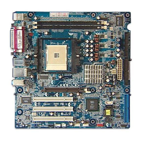
Page 5: Motherboard Layout
Motherboard layout 24.5cm (9.64in) PS/2 T: Mouse B: Keyboard Clear Password DDR XMM2 (64/72 bit, 184-pin module) COM1 DDR XMM1 (64/72 bit, 184-pin module) CHA_FAN1 Bottom: Top: USB1 1394 USB2 ATX12V1 Socket 754 Bottom: Top: USB1 RJ-45 USB2 Top:Line In Center:Line Out BATY1 Below:Mic In... -
Page 6: Central Processing Unit (Cpu)
Central Processing Unit (CPU) The motherboard comes with a surface mount 754-pin Zero Insertion Force (ZIF) socket designed for the AMD Athlon™ 64 processor. Take note of the marked corner (with gold triangle) on the CPU. This mark should match a specific corner on the socket to ensure correct installation. - Page 7 Position the CPU above the socket such that the CPU corner with the gold triangle matches the socket corner with a small triangle. Carefully insert the CPU into the socket until it fits in place. G o l d G o l d G o l d G o l d G o l d...
-
Page 8: System Memory
System memory The motherboard comes with two Double Data Rate (DDR) Dual Inline Memory Module (DIMM) sockets. These sockets support up to 2 GB system memory using 184-pin unbuffered non-ECC PC3200/PC2700/PC2100/ PC1600 double-sided DDR DIMMs. The following figure illustrates the location of the DDR DIMM sockets. 104 Pins 80 Pins K8S-LA... - Page 9 Recommended memory configurations Recommended memory configurations Recommended memory configurations Recommended memory configurations Recommended memory configurations S o c k e t s S o c k e t s S o c k e t s S o c k e t s S o c k e t s M o d e M o d e...
-
Page 10: Expansion Slots
Expansion slots The motherboard has one PCI Express and three PCI slots. To install and configure an expansion card: Install an expansion card following the instructions that came with the chassis. Turn on the system and change the necessary BIOS settings, if any. Assign an IRQ to the card. - Page 11 When using PCI cards on shared slots, ensure that the drivers support “Share IRQ” or that the cards do not need IRQ assignments. Otherwise, conflicts will arise between the two PCI groups, making the system unstable and the card inoperable. AGP slot AGP slot AGP slot...
-
Page 12: Jumpers
Jumpers Clear RTC RAM (3-pin J6) Clear RTC RAM (3-pin J6) Clear RTC RAM (3-pin J6) Clear RTC RAM (3-pin J6) Clear RTC RAM (3-pin J6) This jumper allows you to clear the Real Time Clock (RTC) RAM in CMOS. You can clear the CMOS memory of date, time, and system setup parameters by erasing the CMOS RTC RAM data. - Page 13 Clear password (3-pin J7) Clear password (3-pin J7) Clear password (3-pin J7) Clear password (3-pin J7) Clear password (3-pin J7) This jumper allows you to clear the password if you forgot your password. To erase the password: 1. Turn OFF the computer and unplug the power cord. 2.
-
Page 14: Connectors
Connectors 6 . 1 6 . 1 Rear panel connectors Rear panel connectors 6 . 1 6 . 1 6 . 1 Rear panel connectors Rear panel connectors Rear panel connectors 1 . 1 . P S / 2 m o u s e p o r t ( g r e e n ) . P S / 2 m o u s e p o r t ( g r e e n ) . - Page 15 8 . 8 . U S B 2 . 0 p o r t s 3 a n d 4 . U S B 2 . 0 p o r t s 3 a n d 4 . These two 4-pin Universal Serial Bus U S B 2 .
-
Page 16: Internal Connectors
6 . 2 6 . 2 6 . 2 Internal connectors Internal connectors Internal connectors 6 . 2 6 . 2 Internal connectors Internal connectors This section describes and illustrates the internal connectors on the motherboard. 1 . 1 . F l o p p y d i s k d r i v e c o n n e c t o r ( 3 4 - 1 p i n F L O P P Y 1 ) F l o p p y d i s k d r i v e c o n n e c t o r ( 3 4 - 1 p i n F L O P P Y 1 ) F l o p p y d i s k d r i v e c o n n e c t o r ( 3 4 - 1 p i n F L O P P Y 1 ) - Page 17 2 . 2 . I D E c o n n e c t o r s ( 4 0 - 1 p i n P R I M A R Y _ I D E , S E C O N D A R Y _ I D E ) I D E c o n n e c t o r s ( 4 0 - 1 p i n P R I M A R Y _ I D E , S E C O N D A R Y _ I D E ) I D E c o n n e c t o r s ( 4 0 - 1 p i n P R I M A R Y _ I D E , S E C O N D A R Y _ I D E ) I D E c o n n e c t o r s ( 4 0 - 1 p i n P R I M A R Y _ I D E , S E C O N D A R Y _ I D E )
- Page 18 3 . 3 . ATX power connectors (2 ATX power connectors (2 ATX power connectors (20 0 0 0 0 -pin ATXP ATX power connectors (2 ATX power connectors (2 -pin ATXP -pin ATXP -pin ATXP -pin ATXPW R 1 W R 1 W R 1 W R 1...
-
Page 19: Hard Disk Drives
4 . 4 . S e r i a l A T A c o n n e c t o r s ( 7 - p i n S A T A 1 [ b l a c k ] , S A T A 2 S e r i a l A T A c o n n e c t o r s ( 7 - p i n S A T A 1 [ b l a c k ] , S A T A 2 S e r i a l A T A c o n n e c t o r s ( 7 - p i n S A T A 1 [ b l a c k ] , S A T A 2 S e r i a l A T A c o n n e c t o r s ( 7 - p i n S A T A 1 [ b l a c k ] , S A T A 2... - Page 20 5 . 5 . I E E E 1 3 9 4 a c o n n e c t o r ( 1 0 - 1 p i n I E 1 3 9 4 _ 1 ) I E E E 1 3 9 4 a c o n n e c t o r ( 1 0 - 1 p i n I E 1 3 9 4 _ 1 ) I E E E 1 3 9 4 a c o n n e c t o r ( 1 0 - 1 p i n I E 1 3 9 4 _ 1 ) I E E E 1 3 9 4 a c o n n e c t o r ( 1 0 - 1 p i n I E 1 3 9 4 _ 1 ) I E E E 1 3 9 4 a c o n n e c t o r ( 1 0 - 1 p i n I E 1 3 9 4 _ 1 )
- Page 21 7 7 7 7 7 C P U a n d C h a s s i s F a n c o n n e c t o r s C P U a n d C h a s s i s F a n c o n n e c t o r s C P U a n d C h a s s i s F a n c o n n e c t o r s C P U a n d C h a s s i s F a n c o n n e c t o r s C P U a n d C h a s s i s F a n c o n n e c t o r s...
- Page 22 9 . 9 . D i g i t a l a u d i o c o n n e c t o r ( 4 - 1 p i n S P D I F 1 ) D i g i t a l a u d i o c o n n e c t o r ( 4 - 1 p i n S P D I F 1 ) D i g i t a l a u d i o c o n n e c t o r ( 4 - 1 p i n S P D I F 1 ) D i g i t a l a u d i o c o n n e c t o r ( 4 - 1 p i n S P D I F 1 ) D i g i t a l a u d i o c o n n e c t o r ( 4 - 1 p i n S P D I F 1 )
- Page 23 1 1 . 1 1 . 1 1 . S y s t e m p a n e l c o n n e c t o r ( 1 0 - p i n F _ P A N E L 1 ) S y s t e m p a n e l c o n n e c t o r ( 1 0 - p i n F _ P A N E L 1 ) S y s t e m p a n e l c o n n e c t o r ( 1 0 - p i n F _ P A N E L 1 ) S y s t e m p a n e l c o n n e c t o r ( 1 0 - p i n F _ P A N E L 1 )
- Page 24 A S U S K 8 S - L A ( S a l m o n ) A S U S K 8 S - L A ( S a l m o n ) A S U S K 8 S - L A ( S a l m o n ) A S U S K 8 S - L A ( S a l m o n ) A S U S K 8 S - L A ( S a l m o n )
Need help?
Do you have a question about the K8S-LA (Salmon) and is the answer not in the manual?
Questions and answers