Sony Discman D-180AN Service Manual
Compact disc compact player
Hide thumbs
Also See for Discman D-180AN:
- Operating instructions (2 pages) ,
- Operating instructions (2 pages)
Table of Contents
Advertisement
D-180AN/180ANC/181/181C/181V/182CK/183
SERVICE MANUAL
CD player
System
Compact disc digital audio system
Laser diode properties
Material: GaAIAs
Wavelength : λ= 780 nm
Emission duration: Continuous
Laser output : Less than 44.6 µW (This output
is the value measured at a distance of 200 mm
from the objective lens surface on the optical
pick-up block with 7 mm aperture. )
Error correction
Sony Super Strategy Cross Interleave Reed
Solomon Code
D-A conversion
1-bit quartz time-axis control
Frequency response
+1
20 - 20,000 Hz
dB (measured by EIAJ CP-
-2
307)
Output (at 4.5 V input level)
Headphones (stereo minijack)
15 mW + 15 mW at 16 ohms
Line output (stereo minijack)
Output level 0.7 V rms at 47 kilohms
Recommended load impedance over 10
kilohms
General
Power requirements
For the area code of the model you purchased,
check the upper left side of the bar code on the
package.
• Sony BP-DM10 Rechargeable battery:
2.4 V DC, Ni-Cd. 650 mAh
Sony BP-DM20 Rechargeable battery:
2.4 V DC, Ni-Mh, 1,200 mAh
• Two LR6 (size AA) batteries: 3 V DC
MICROFILM
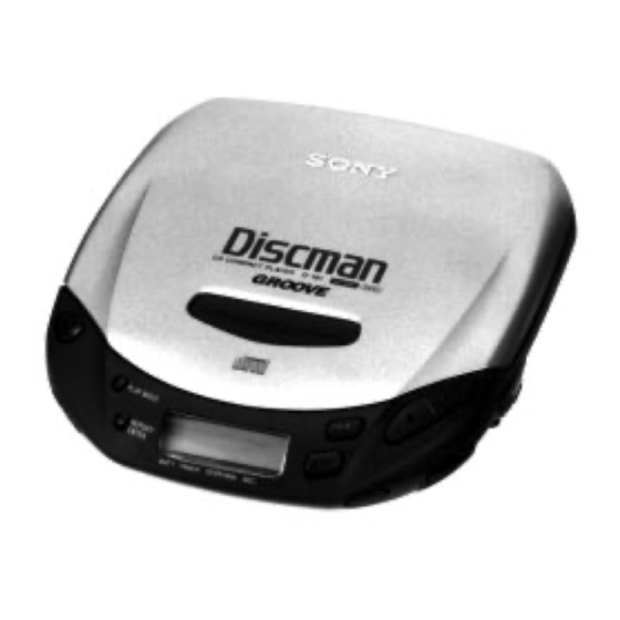
Photo : D-181
Model Name Using Similar Mechanism
CD Mechanism Type
Optical Pick-up Type
SPECIFICATIONS
• AC power adaptor (DC IN 4.5 V jack):
US, Canadian, Central and South America
model: 120 V, 60 Hz
AEP, Italian, French, E13, EE model:
220 - 230 V, 50/60 Hz
UK model: 230 - 240 V, 50 Hz
EA model: 110 - 240 V, 50/60 Hz
AUS model: 240 V, 50 Hz
Tourist, E33 model: 100 - 240 V, 50/60 Hz
Hong Kong model: 220 V, 50/60 Hz
Chinese model: 220 V, 50 Hz
• Sony CPM-300P mount plate for use on car
battery : 4.5V DC
Dimensions (w/h/d) (without projecting parts and
controls)
Approx. 129 x 28.1 x 146 mm
( 5
1
/
x 1
1
/
x 5
3
/
in.)
8
8
4
Mass (without rechargeable battery)
Approx. 220 g (7.8 oz)
Operating temperature
5°C - 35°C (41°F - 95°F)
Supplied accessories
For the area code of the model you purchased,
check the upper left side of the bar code on the
package.
D- 180AN/180ANC
Earphones (1)
D-181/181C
AC power adaptor (1)
Earphones (1)
Connecting cord (Phono plug x 2˜ stereo
miniplug) (1)
COMPACT DISC COMPACT PLAYER
Canadian Model
D-181/182CK/183
AEP Model
D-180AN/180ANC/181/
181C/181V/182CK/183
UK Model
E Model
D-180AN/181/181C/182CK/183
Australian Model
D-181/182CK/183
Chinese Model
D-180AN/181/182CK/183
NEW
CDM-2811AAA
DAX-01A
AC plug adaptor (1)*
*Supplied with E33, E13 and EA models
D-181V
AC power adaptor (1)
Earphones with volume control (1)
Connecting cord (Phono plug x 2˜ stereo
miniplug) (1)
D-183
AC power adaptor (1)
Earphones (1)
Rechargeable battery (1)
Connecting cord (Phono plug x 2 ˜ stereo
miniplug) (1)
AC plug adaptor (1)*
*Supplied with E33, E13 and EA models
D-182CK
AC power adaptor (1)
Earphones (1)
Connecting cord (Phono plug x 2 ˜ stereo
miniplug) (1)*
1
Car battery cord (1)
Car connecting pack (1)
Mount plate (1)
Velcro tape (2)
Spare fuse (1)
Spiral tube (1)
AC plug adaptor (1)*
2
*
1
Not supplied with AEP model
*
2
Supplied with E33, E13 and EA models
Design and specifications are subject to
change without notice.
D-181/183
Advertisement
Table of Contents


Need help?
Do you have a question about the Discman D-180AN and is the answer not in the manual?
Questions and answers