Table of Contents
Advertisement
Quick Links
Download this manual
See also:
Setup Manual
Advertisement
Table of Contents

Subscribe to Our Youtube Channel
Related Manuals for ProSoft Technology inRA-x ILX34-AENWG

Summary of Contents for ProSoft Technology inRA-x ILX34-AENWG
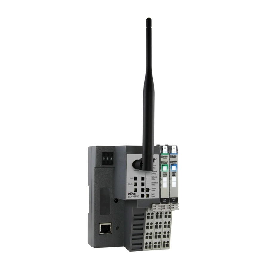
- Page 1 ILX34-AENWG Point I/O Platform Wireless POINT I/O Adapter August 16, 2013 USER MANUAL...
-
Page 2: Your Feedback Please
In an effort to conserve paper, ProSoft Technology no longer includes printed manuals with our product shipments. User Manuals, Datasheets, Sample Ladder Files, and Configuration Files are provided on the enclosed DVD and are available at no charge from our web site: http://www.prosoft-technology.com... -
Page 3: Important User Information
In no event will ProSoft Technology be responsible or liable for indirect or consequential damage resulting from the use or application of these products. -
Page 4: Important Installation Instructions
Caution: POINT I/O is grounded through the DIN-rail to chassis ground. Use zinc-plated, yellow-chromated steel DIN-rail to assure proper grounding. Using other DIN-rail materials (for example, aluminum, plastic, and so on) which can corrode, oxidize or are poor conductors, can result in improper or intermittent platform grounding. Caution: When you connect or disconnect the Removable Terminal Block (RTB) with field side power applied, an electrical arc can occur. -
Page 5: North American Hazardous Location Approval
North American Hazardous Location Approval The following information applies when operating this equipment in hazardous locations: Products marked "CL I, DIV 2, GP A, B, C, D" are suitable for use in Class I Division 2 Groups A, B, C, D, Hazardous Locations and nonhazardous locations only. -
Page 7: Table Of Contents
Configuring Wireless Settings in RSLogix 5000 ............. 44 Install the Antenna ....................45 Test the Network Installation Plan ................46 About the Example Applications Support of Rack-optimized and Direct Connections ..........48 ProSoft Technology, Inc. Page 7 of 177 August 16, 2013... - Page 8 Installing the Connected Components Workshop package ........103 4.11.3 Configuring RSLinx ....................106 4.11.4 Installing the Firmware Package................109 4.11.5 Flash programming the ILX34 ................110 4.11.6 Testing the new firmware installation ..............115 Page 8 of 177 ProSoft Technology, Inc. August 16, 2013...
- Page 9 Configure the AB_ETH/IP Driver ................167 Using the ILX34-AENWG with Earlier Versions of RSLogix 5000 ......170 Additional Point I/O Documentation ..............170 Support, Service & Warranty Contacting Technical Support ......................173 ProSoft Technology, Inc. Page 9 of 177 August 16, 2013...
- Page 10 Contents ILX34-AENWG ♦ Point I/O Platform User Manual Wireless POINT I/O Adapter Warranty Information .................... 174 Index Page 10 of 177 ProSoft Technology, Inc. August 16, 2013...
-
Page 11: Guide To The Ilx34-Aenwg User Manual
Adapter and POINT I/O Processor Support, Service, and Support, Service & Obtaining Technical Support Warranty Warranty (page 173) Contacting ProSoft Technology Index License and Warranty Index ProSoft Technology, Inc. Page 11 of 177 August 16, 2013... - Page 12 Start Here ILX34-AENWG ♦ Point I/O Platform User Manual Wireless POINT I/O Adapter Page 12 of 177 ProSoft Technology, Inc. August 16, 2013...
-
Page 13: Start Here
Supported systems include: ® ® Rockwell Automation (RA) ControlLogix Programmable Automation Controller (PAC) systems RA CompactLogix™ (CPLX) PAC systems ProSoft Technology, Inc. Page 13 of 177 August 16, 2013... -
Page 14: Package Contents
2.4 GHz Articulating Omni Antenna ProSoft Solutions DVD-001 Contains utilities and documentation for the ILX34-AENWG Adapter. If any of these components are missing, please contact ProSoft Technology Support for replacement parts. System Requirements The ILX34-AENWG adapter requires the following minimum hardware and software components: ®... -
Page 15: Install The Configuration Tools
DVD drive Note: The Hardware and Operating System requirements in this list are the minimum recommended to install and run software provided by ProSoft Technology. Other third party applications may have different minimum requirements. Refer to the documentation for any third party applications for system requirements. -
Page 16: Planning The Network
Choose the appropriate antennas for the network. If an antenna will be connected to the radio by a long cable, you might need to purchase a power amplifier, which is available from ProSoft Technology. The more distance between an antenna and its radio, the more signal loss the radio will have. -
Page 17: Prosoft Wireless Designer
Discover and view the list of radios in the network Display graphically the current network topology and display parent-child links between various radios in the network ProSoft Technology, Inc. Page 17 of 177 August 16, 2013... -
Page 18: Planning The Physical Installation
Configure the Wireless Access Point Although the ILX34-AENWG can communicate with any 802.11b/g Access Point radio, ProSoft Technology recommends the RadioLinx series Industrial Broadband radios wherever performance and compatibility are required. The following configuration steps are for the RLXIB-IHW. Use the examples in these steps to configure your own Access Point to work with the ILX34-AENWG. - Page 19 Protocol) to manage and assign IP addresses Configure the Adapter for Your EtherNet/IP Network (page 24). Note: Refer to the documentation for your radio (for example, the RLXIB-IHW User Manual) for specific steps to configure the settings in this example. ProSoft Technology, Inc. Page 19 of 177 August 16, 2013...
-
Page 20: Configure One Or More Repeaters (Optional)
Install the Adapter Attention: You must use series C POINT I/O modules with the ILX34-AENWG adapter. Series A or B POINT I/O modules will not work with this adapter. Page 20 of 177 ProSoft Technology, Inc. August 16, 2013... -
Page 21: Adapter Components
Refer to the documentation for each device you plan to connect to verify that suitable safety procedures are in place before installing or servicing the device. Position the adapter vertically above the DIN-rail. ProSoft Technology, Inc. Page 21 of 177 August 16, 2013... -
Page 22: Connect Power To The Adapter
Caution: Do not connect 120/240V ac power to this supply. Warning: If you connect or disconnect wiring while the field-side power is on, an electrical arc can occur. This could cause an explosion in hazardous location installations. Page 22 of 177 ProSoft Technology, Inc. August 16, 2013... - Page 23 Module Status LED. One by one, the adapter resets these modules and assigns addresses. The amount of time that this operation takes depends on the size of your POINT I/O system. ProSoft Technology, Inc. Page 23 of 177 August 16, 2013...
-
Page 24: Connect The Adapter To The Ethernet/Ip Network
B POINT I/O modules will not work with this adapter. Configure the IP Address with the Thumbwheel Switches ore you can connect to the ILX34-AENWG for the first time, you must configure its IP address. Page 24 of 177 ProSoft Technology, Inc. August 16, 2013... - Page 25 DHCP is based on BootP and maintains some backward compatibility. The main difference is that BootP was designed for manual configuration, while DHCP allows for dynamic allocation of network addresses and configurations to newly attached devices. ProSoft Technology, Inc. Page 25 of 177 August 16, 2013...
- Page 26 To configure the ILX34-AENWG adapter with a fixed IP address Click the P tab in the ILX34-AENWG adapter properties ONFIGURATION dialog. Unselect (uncheck) the E DHCP check box. NABLE Page 26 of 177 ProSoft Technology, Inc. August 16, 2013...
- Page 27 To configure your adapter using the BootP utility, perform the following steps: Run the BootP software. In the BOOTP R pane, you will see the hardware addresses EQUEST ISTORY of devices on the network that are issuing BootP requests. ProSoft Technology, Inc. Page 27 of 177 August 16, 2013...
- Page 28 D BOOTP/DHCP button. The device will ISABLE use the assigned configuration the next time it is powered up, and will no longer issue DHCP requests. Page 28 of 177 ProSoft Technology, Inc. August 16, 2013...
- Page 29 You can save the Relation List to use later, for example, to have a record of IP addresses assigned to specific MAC addresses. Open the F menu, and then choose S ProSoft Technology, Inc. Page 29 of 177 August 16, 2013...
-
Page 30: Configure The Ilx34-Aenwg For Wireless Access
The right column contains links for additional resources and information. To view the contents of a folder, click the E button. XPAND Page 30 of 177 ProSoft Technology, Inc. August 16, 2013... - Page 31 ONFIGURATION in the menu on the left side of the page, and then click the W IRELESS ETTINGS link. Use this page to configure the radio settings for the adapter. ProSoft Technology, Inc. Page 31 of 177 August 16, 2013...
- Page 32 WPA2/AES pass phrase of between eight and 63 normal keyboard characters. This phrase automatically generates an encryption key of 128 hexadecimal characters. This field is only available if you select WPA2/AES as the encryption type. Page 32 of 177 ProSoft Technology, Inc. August 16, 2013...
-
Page 33: Verify Wireless Communication
In this condition, the link LED on the ILX34-AENWG will periodically come on and then go off. Also, the Wireless Statistics web page will sometimes show the unit is linked and then later show that it is not. ProSoft Technology, Inc. Page 33 of 177 August 16, 2013... - Page 34 ILX34-AENWG ♦ Point I/O Platform User Manual Wireless POINT I/O Adapter Page 34 of 177 ProSoft Technology, Inc. August 16, 2013...
-
Page 35: Configure The Ilx34-Aenwg
RSLogix 5000 or the processor firmware, please refer to Using the ILX34- AENWG with Earlier Versions of RSLogix 5000 (page 170). … Open the F menu, and then choose N ProSoft Technology, Inc. Page 35 of 177 August 16, 2013... -
Page 36: Create The Network
Configure the ILX34-AENWG ILX34-AENWG ♦ Point I/O Platform User Manual Wireless POINT I/O Adapter Select R EVISION Create the Network … Right-click I/O C and choose N ONFIGURATION ODULE Page 36 of 177 ProSoft Technology, Inc. August 16, 2013... - Page 37 Note: If you are prompted to "Select Major Revision", choose the lower of the available revision numbers. Name the ENBT/A module, then set the IP Address and slot location in the local rack with the ControlLogix processor. Click OK. ProSoft Technology, Inc. Page 37 of 177 August 16, 2013...
-
Page 38: Create The Adapter
ELECT ODULE ENDOR node. Click the B tab, expand the P ECHNOLOGY ENDOR node, and then select ILX34-AENWG. ECHNOLOGY Name the ILX34-AENWG adapter, and set the IP address. Page 38 of 177 ProSoft Technology, Inc. August 16, 2013... -
Page 39: Configure Chassis Size
When the adapter's non-volatile chassis size does not match the actual number of modules present on its backplane, the adapter does not make any I/O connections and an error occurs. ProSoft Technology, Inc. Page 39 of 177 August 16, 2013... -
Page 40: Add Point Modules Under The Adapter
Controller Tags. In the C window, double-click C ONTROLLER RGANIZATION ONTROLLER and then click the M tab, at the bottom left corner of the ONITOR Controller Tags dialog box. Page 40 of 177 ProSoft Technology, Inc. August 16, 2013... - Page 41 View the value in the tag ILX34_AENWG:2:C.C . The default ANGE value for this tag is 2. The module supports the following Ch0Range Type values: 2 = 0 to 10V dc ProSoft Technology, Inc. Page 41 of 177 August 16, 2013...
- Page 42 We highly recommend that you use the inhibit/uninhibit process and avoid power cycling. Right-click the ILX34-AENWG adapter and select P ROPERTIES Page 42 of 177 ProSoft Technology, Inc. August 16, 2013...
- Page 43 1 (the factory default value) until you reset this size manually. Note: You must be online to the adapter to change this setting. Click the C tab. HASSIS ProSoft Technology, Inc. Page 43 of 177 August 16, 2013...
-
Page 44: Configuring Wireless Settings In Rslogix 5000
Settings and Wireless Statistics tabs are populated only when the processor is online to the ILX34- AENWG. Note: Allow sufficient time (30 to 60 seconds) for RSLogix 5000 to send and receive wireless settings from the ILX34-AENWG. Page 44 of 177 ProSoft Technology, Inc. August 16, 2013... -
Page 45: Install The Antenna
Antenna Polarity (page 162). Antennas with a reverse polarity SMA connector can be mounted directly on the radio. Screw the antenna onto the antenna port connector until snug. ProSoft Technology, Inc. Page 45 of 177 August 16, 2013... -
Page 46: Test The Network Installation Plan
Note: The use of any antenna that is not on the ProSoft Technology approved antennas list may result in radio transmissions that violate your country's wireless regulatory laws, which may lead to civil liabilities or criminal penalties. -
Page 47: About The Example Applications
Access Point. To prevent a loop from occurring, avoid connecting Ethernet cables to the Access Point and the ILX34-AENWG at the same time after the wireless link is established. ProSoft Technology, Inc. Page 47 of 177 August 16, 2013... -
Page 48: Support Of Rack-Optimized And Direct Connections
POINT I/O modules on an EtherNet/IP network. Quantity Product Name Catalog Number Hardware Wireless POINT I/O Adapter ILX34-AENWG POINT I/O 24V dc sink output 1734-OV4E/C module Page 48 of 177 ProSoft Technology, Inc. August 16, 2013... -
Page 49: Set Up The Hardware
This example configures your ILX34-AENWG for both direct connection and rack optimization using RSLogix 5000 software. You can mix communication formats for different I/O modules communicating through the same adapter. ProSoft Technology, Inc. Page 49 of 177 August 16, 2013... -
Page 50: Add The Relay Output Module And Configure For Direct Connection
In the S dialog box, choose the 1734-OW2 relay output ELECT ODULE module from the list, and click OK. In the M dialog, enter the following information: ODULE ROPERTIES a) Name Page 50 of 177 ProSoft Technology, Inc. August 16, 2013... - Page 51 Wireless POINT I/O Adapter User Manual b) Slot In the Module Definition area, click the C ... button, and change the HANGE Connection type from Rack Optimization (default) to D ProSoft Technology, Inc. Page 51 of 177 August 16, 2013...
-
Page 52: Add The Digital Output Module And Configure For Rack Optimization
The following illustration shows the I/O Configuration for this project. 3.4.2 Add the Digital Output Module and Configure for Rack Optimization Right-click the ILX34-AENWG adapter under the I/O Configuration folder and select N ODULE Page 52 of 177 ProSoft Technology, Inc. August 16, 2013... - Page 53 In the S dialog box, choose the 1734-OV4E digital output ELECT ODULE module from the list, and click OK. In the M dialog, enter the following information: ODULE ROPERTIES a) Name ProSoft Technology, Inc. Page 53 of 177 August 16, 2013...
- Page 54 Important: To avoid overloading the ILX34-AENWG adapter, we recommend that RPI be no less than 10 ms for rack connections and 50 ms for direct connections. Click OK save the configuration. Page 54 of 177 ProSoft Technology, Inc. August 16, 2013...
-
Page 55: Downloading The Sample Program To The Processor
When the download is complete, RSLogix 5000 will open another confirmation dialog box. If the key switch is in the REM position, click OK to switch the processor from PROGRAM mode to RUN mode. ProSoft Technology, Inc. Page 55 of 177 August 16, 2013... -
Page 56: Verify The Chassis Size
ROPERTIES On the M dialog box, click the C tab. Notice ODULE ROPERTIES ONNECTION that the M area of the dialog box contains information about the ODULE AULT error code. Page 56 of 177 ProSoft Technology, Inc. August 16, 2013... - Page 57 LICK HASSIS IZE IN button. ODULE This action opens a notification dialog box. Take any necessary steps to prevent hazardous conditions, and then click OK to dismiss the dialog box. ProSoft Technology, Inc. Page 57 of 177 August 16, 2013...
-
Page 58: View Module Data
RSLogix 5000. The following illustration shows the ILX34-AENWG configured with the sample application. POINT_IO_Adapter = the name you gave to your Ethernet adapter # = slot number of POINT I/O module Page 58 of 177 ProSoft Technology, Inc. August 16, 2013... -
Page 59: Example 2 - Direct Connection
The adapter makes a direct connection to each of the modules referenced by the data. Attention: You must use series C POINT I/O modules with the ILX34-AENWG adapter. Series A or B POINT I/O modules will not work with this adapter. ProSoft Technology, Inc. Page 59 of 177 August 16, 2013... -
Page 60: Add The Relay Output Module And Configure For Direct Connection
In the S dialog box, choose the 1734-OW2 relay output ELECT ODULE module from the list, and click OK. In the M dialog, enter the following information: ODULE ROPERTIES a) Name Page 60 of 177 ProSoft Technology, Inc. August 16, 2013... - Page 61 Wireless POINT I/O Adapter User Manual b) Slot In the Module Definition area, click the C ... button, and change the HANGE Connection type from Rack Optimization (default) to D ProSoft Technology, Inc. Page 61 of 177 August 16, 2013...
-
Page 62: Add The Digital Output Module And Configure For Direct Connection
The following illustration shows the I/O Configuration for this project. 3.5.2 Add the Digital Output Module and Configure for Direct Connection Right-click the ILX34-AENWG adapter under the I/O Configuration folder and select N ODULE Page 62 of 177 ProSoft Technology, Inc. August 16, 2013... - Page 63 In the S dialog box, choose the 1734-OV4E digital output ELECT ODULE module from the list, and click OK. In the M dialog, enter the following information: ODULE ROPERTIES a) Name ProSoft Technology, Inc. Page 63 of 177 August 16, 2013...
- Page 64 User Manual Wireless POINT I/O Adapter b) Slot In the Module Definition area, click the C ... button, and change the HANGE Connection type from Rack Optimization (default) to D Page 64 of 177 ProSoft Technology, Inc. August 16, 2013...
-
Page 65: Edit The Controller Tags
Double-click the C folder in the project dialog. ONTROLLER The action opens the C dialog box. You will see the tags ONTROLLER created for the ILX34-AENWG adapter and digital I/O modules. ProSoft Technology, Inc. Page 65 of 177 August 16, 2013... -
Page 66: Create The Ladder Program
Next, create the example ladder program to test the I/O. Double-click M under the Main Program folder. OUTINE Enter the following ladder program using the tags previously created. Save the program. Page 66 of 177 ProSoft Technology, Inc. August 16, 2013... -
Page 67: Downloading The Sample Program To The Processor
You must configure the chassis size for the ILX34-AENWG before you can make any I/O Configure Chassis Size (page 39). The default setting for the chassis size is 1 slot, which represents the adapter by itself. ProSoft Technology, Inc. Page 67 of 177 August 16, 2013... - Page 68 ROPERTIES On the M dialog box, click the C tab. Notice ODULE ROPERTIES ONNECTION that the M area of the dialog box contains information about the ODULE AULT error code. Page 68 of 177 ProSoft Technology, Inc. August 16, 2013...
- Page 69 LICK HASSIS IZE IN button. ODULE This action opens a notification dialog box. Take any necessary steps to prevent hazardous conditions, and then click OK to dismiss the dialog box. ProSoft Technology, Inc. Page 69 of 177 August 16, 2013...
-
Page 70: View Module Data
RSLogix 5000. The following illustration shows the ILX34-AENWG configured with the sample application. ILX34_AENWG = the name you gave to your Ethernet adapter # = slot number of POINT I/O module Page 70 of 177 ProSoft Technology, Inc. August 16, 2013... - Page 71 The slot status bits indicate that the module in slot 2 is operating correctly: 0=module participating with no errors and 1=module not participating or connection error (typically, module removed/missing) ProSoft Technology, Inc. Page 71 of 177 August 16, 2013...
- Page 72 ILX34-AENWG ♦ Point I/O Platform User Manual Wireless POINT I/O Adapter Page 72 of 177 ProSoft Technology, Inc. August 16, 2013...
-
Page 73: Diagnostics And Troubleshooting
The right column contains links for additional resources and information. To view the contents of a folder, click the E button. XPAND ProSoft Technology, Inc. Page 73 of 177 August 16, 2013... -
Page 74: Diagnostics
The Diagnostics pages automatically refresh at 15 second intervals. To change the refresh interval, enter a value in seconds in the R ) field at EFRESH the top of the page. Page 74 of 177 ProSoft Technology, Inc. August 16, 2013... - Page 75 MAC Address and IP Address. System Resource Utilization Field Description CPU Utilization Indicates the percentage of the time the adaptor's CPU (Central Processing Unit) is working. Peak CPU utilization is shown in parentheses. ProSoft Technology, Inc. Page 75 of 177 August 16, 2013...
- Page 76 If the number of timeouts is high, the network traffic is likely too high. LED Status: Field Description Module Status Flashing red = an error condition Solid green = functioning properly Page 76 of 177 ProSoft Technology, Inc. August 16, 2013...
- Page 77 Ethernet and Antenna ports on the ILX34-AENWG. Note: The values on this page are for information only, and cannot be modified. To change these values, use the Network Configuration Page (page 87). ProSoft Technology, Inc. Page 77 of 177 August 16, 2013...
- Page 78 E link on the left side of the page. THERNET TATISTICS Use this page to view detailed status information for the Ethernet and Antenna ports on the ILX34-AENWG. Page 78 of 177 ProSoft Technology, Inc. August 16, 2013...
- Page 79 10 megabits or 100 megabits Duplex Half Duplex or Full Duplex Autonegotiation Status Autonegotiate Speed and Duplex, or Force Speed and Duplex Interface Counters Field Description In Octets Number of octets (bytes) received ProSoft Technology, Inc. Page 79 of 177 August 16, 2013...
- Page 80 Check the device to insure that it is functioning correctly. Carrier Sense Errors The number of times that the carrier sense condition was lost or never asserted when attempting to transmit a frame on a particular interface. Page 80 of 177 ProSoft Technology, Inc. August 16, 2013...
- Page 81 Shows the number of lost packets and the slot number for the connection. A slot value of 0 indicates that this is a rack- optimized connection. Size Size of data in bytes ProSoft Technology, Inc. Page 81 of 177 August 16, 2013...
- Page 82 Attribute (decimal) Refer to the documentation for each POINT I/O module for supported Attribute types Timeout (seconds) The number of seconds to wait for a response from the POINT I/O module Page 82 of 177 ProSoft Technology, Inc. August 16, 2013...
- Page 83 All", sent to the I/O module in Slot 1. The data is returned in hexadecimal format. Refer to the documentation for each POINT I/O Additional Point I/O Documentation (page 170) to determine the meaning of the response. ProSoft Technology, Inc. Page 83 of 177 August 16, 2013...
-
Page 84: Wireless Statistics Page
Although this field is informational, some packets, such as 802.11 management packets, will be at a rate that is lower than the data. In such an instance, the data could be going at a rate faster than this. Page 84 of 177 ProSoft Technology, Inc. August 16, 2013... - Page 85 14 dB -74 dBm 16 dB -72 dBm 18 dB -70 dBm 20 dB -68 dBm 22 dB -66 dBm 24 dB -64 dBm 26 dB -62 dBm 28 dB ProSoft Technology, Inc. Page 85 of 177 August 16, 2013...
-
Page 86: Configuration
ILX34-AENWG adapter's name, location and chassis size. Important: The values on this page are in non-volatile memory. Changes to these parameters do not take effect until you reset or cycle power to the ILX34-AENWG adapter. Page 86 of 177 ProSoft Technology, Inc. August 16, 2013... - Page 87 ILX34-AENWG adapter's TCP/IP and Ethernet port settings. Important: The values on this page are in non-volatile memory. Changes to these parameters do not take effect until you reset or cycle power to the ILX34-AENWG adapter. ProSoft Technology, Inc. Page 87 of 177 August 16, 2013...
- Page 88 ONFIGURATION menu on the left side of the page, and then click the S link. Use this page ERVICES to disable the adaptor's web server, or to change the password. Page 88 of 177 ProSoft Technology, Inc. August 16, 2013...
-
Page 89: Wireless Settings Page
ONFIGURATION in the menu on the left side of the page, and then click the W IRELESS ETTINGS link. Use this page to configure the radio settings for the adapter. ProSoft Technology, Inc. Page 89 of 177 August 16, 2013... - Page 90 WPA2/AES pass phrase of between eight and 63 normal keyboard characters. This phrase automatically generates an encryption key of 128 hexadecimal characters. This field is only available if you select WPA2/AES as the encryption type. Page 90 of 177 ProSoft Technology, Inc. August 16, 2013...
-
Page 91: Browse Chassis Page
This selection is useful when browsing a busy system. Tip: Select (check) the D check box to reduce the font size and limit scrolling for ISPLAY OMPACT systems with a large number of modules. ProSoft Technology, Inc. Page 91 of 177 August 16, 2013... - Page 92 Click the link to view information ODULE ESCRIPTION about the module. Note: The information on the M page depends on the type and configuration of ODULE NFORMATION the module. Page 92 of 177 ProSoft Technology, Inc. August 16, 2013...
-
Page 93: Viewing Wireless Statistics In Rslogix 5000
Since I/O messaging is latency dependent, its important that other 802.11 networks do not interfere with the I/O network. It is recommended that the network use a channel free of interference from other 802.11 devices. ProSoft Technology, Inc. Page 93 of 177 August 16, 2013... -
Page 94: Establish I/O Connections
I/O. The ILX34-AENWG adapter continuously monitors this bandwidth and rejects requests for new connections when there is insufficient bandwidth available to support the new connection. Page 94 of 177 ProSoft Technology, Inc. August 16, 2013... -
Page 95: Empty Slots And Riup Situations
Because the adapter cannot detect empty terminal bases, it cannot assume any safe operation until there is a match between the number of modules indicating their presence in the chassis and what the adapter has saved in non-volatile memory. ProSoft Technology, Inc. Page 95 of 177 August 16, 2013... - Page 96 These removal and return situations exist whether the system is under power or not. If the system is under power, the situation arises immediately. If the system is not under power, the situation arises in the next power cycle. Page 96 of 177 ProSoft Technology, Inc. August 16, 2013...
-
Page 97: Led Status Indicators
Self-test failure present (checksum failure, or ramtest failure at cycle power). Firmware fatal error present. 4.6.2 Network Activity Indication Probable Cause Recommended Action No link established. Verify network cabling, and correct, as needed. ProSoft Technology, Inc. Page 97 of 177 August 16, 2013... -
Page 98: Network Status
2. If condition persists, replace device. Flashing Firmware (NVS) update in progress. None Green Solid Green Adapter online with connections None established (normal operation, Run mode). Page 98 of 177 ProSoft Technology, Inc. August 16, 2013... -
Page 99: System Power
Use a cross-over cable when connecting the Ethernet radio directly to any device that is NOT a switch or a hub (for example, a direct connection to a PC, PLC, or printer). ProSoft Technology, Inc. Page 99 of 177 August 16, 2013... -
Page 100: Cable Connections
Restoring the network settings to factory defaults depends on the version of firmware in your ILX34. Firmware Versions 3.4.xxx Turn module power off. Change thumbwheels to 888. Turn module power on. Page 100 of 177 ProSoft Technology, Inc. August 16, 2013... -
Page 101: Restoring All Factory Default Settings
The Web server is enabled. The password for this page resets to the factory default of " ". PASSWORD Restoring All Factory Default Settings Turn module power off. ProSoft Technology, Inc. Page 101 of 177 August 16, 2013... -
Page 102: Installing A Replacement Wireless Point I/O Adapter To An Existing System
Set the node address on the node address thumbwheel. Insert the end of the terminal block (RTB) opposite the handle into the base unit. This end has a curved section that engages with the wiring base. Page 102 of 177 ProSoft Technology, Inc. August 16, 2013... -
Page 103: Upgrading To Firmware Version 3.5.0
After expansion, go to the System folder, then the ControlFLASH folder. Rename ControlFLASH to something else (e.g. XControlFLASH). This will prevent installation of an obsolete version of ControlFLASH that will interfere with a newer version we will install later. ProSoft Technology, Inc. Page 103 of 177 August 16, 2013... - Page 104 Device Driver v6.3a, then click Next. In the following screen, enter your user name and company, then click Next. Accept the license agreement in the next screen and click Next. Page 104 of 177 ProSoft Technology, Inc. August 16, 2013...
- Page 105 In the next screen, click Install. Installation will start and you will see some progress screens like the following: When the system tries to install ControlFLASH v9.00.015, it will display this dialog: ProSoft Technology, Inc. Page 105 of 177 August 16, 2013...
-
Page 106: Configuring Rslinx
From your start menu, go to S -> P -> R -> TART ROGRAMS OCKWELL OFTWARE , then run RSLinx Classic. You should see a new icon in your system tray like this: Page 106 of 177 ProSoft Technology, Inc. August 16, 2013... - Page 107 -> OMMUNICATIONS … ONFIGURE RIVERS From the list of Available Driver Types, select E /IP D , then THER RIVER … click A The following dialog will appear; click OK. ProSoft Technology, Inc. Page 107 of 177 August 16, 2013...
- Page 108 ILX34-AENWG ♦ Point I/O Platform User Manual Wireless POINT I/O Adapter Next the following dialog will appear; click OK. Finally you should see the following dialog. Click C and exit RSLinx Classic Lite. LOSE Page 108 of 177 ProSoft Technology, Inc. August 16, 2013...
-
Page 109: Installing The Firmware Package
Click N Accept (Agree with) the license agreement in the next dialog, then click N Click N to install the application in the default location. Click N again to confirm installation. ProSoft Technology, Inc. Page 109 of 177 August 16, 2013... -
Page 110: Flash Programming The Ilx34
4.11.5 Flash programming the ILX34 After installation you should see this dialog: Select Y FLASH, then click C . You WANT TO LAUNCH ONTROL LOSE should see something like the following: Click N > Page 110 of 177 ProSoft Technology, Inc. August 16, 2013... - Page 111 Wireless POINT I/O Adapter User Manual You will be presented with a dialog like the following. There may be additional catalog numbers listed for your system. Select ILX34-AENWG and click N > ProSoft Technology, Inc. Page 111 of 177 August 16, 2013...
- Page 112 Diagnostics and Troubleshooting ILX34-AENWG ♦ Point I/O Platform User Manual Wireless POINT I/O Adapter You should see a dialog like the following: Click on AB_ETHIP-1, E on the left pane. THERNET Page 112 of 177 ProSoft Technology, Inc. August 16, 2013...
- Page 113 For our example, we will flash the device shown at IP address 192.168.1.90. (Note that the device at 192.168.1.99 was detected in a previous ControlFLASH session, but it can be ignored.) ProSoft Technology, Inc. Page 113 of 177 August 16, 2013...
- Page 114 Select Revision 3.5.0, which should be the only firmware version that appears, then click N >. You will get something like: Click F , then Y to begin flash update programming the ILX34- INISH AENWG. Page 114 of 177 ProSoft Technology, Inc. August 16, 2013...
-
Page 115: Testing The New Firmware Installation
Turn off the power to your ILX34, wait a few seconds, then turn power on. Once the Point Bus Status LED is no longer solid RED, the unit should be operational with the new firmware. ProSoft Technology, Inc. Page 115 of 177 August 16, 2013... - Page 116 You should see a screen like the following: The important thing to notice is that the Product Revision is 3.005 Build 0, which is the version of firmware that you just installed. Page 116 of 177 ProSoft Technology, Inc. August 16, 2013...
-
Page 117: Ladder Logic
In the C window, expand the D ONTROLLER RGANIZATION YPES folders, and then double-click AENWGDATA. This action EFINED opens an edit window for the AENWGDATA data type. ProSoft Technology, Inc. Page 117 of 177 August 16, 2013... -
Page 118: 1734 Point I/O Module/Rslogix 5000 Controller Tag Reference
1734 POINT I/O Module/RSLogix 5000 Controller Tag Reference Attention: You must use series C POINT I/O modules with the ILX34-AENWG adapter. Series A or B POINT I/O modules will not work with this adapter. Page 118 of 177 ProSoft Technology, Inc. August 16, 2013... -
Page 119: 1734 Point I/O Catalog Numbers
1 Channel 15…24V dc Very High-speed Counter 1734-VHSC5/C 1 Channel 5V dc Very High-speed Counter Note: All POINT I/O modules must be series C or above for RSLogix 5000 software, version 11, compatibility. ProSoft Technology, Inc. Page 119 of 177 August 16, 2013... -
Page 120: Valid Number Ranges For Rslogix 5000 Data Types
To enter Filter values from +32,768 to +65,535 s, use this conversion formula: Desired Filter Value (in s) - 65536 = Entered Filter Value (in s). Example: for a 40 ms filter time, 40000 - 65536 = -25536 Page 120 of 177 ProSoft Technology, Inc. August 16, 2013... -
Page 121: Digital 4 Point Input
5.2.5 Digital 2 POINT Output - Without Diagnostic Status 1734 POINT I/O Catalog Number RSLogix5000 Module Description 1734-OA2 2 POINT 120V ac Output 1734-OW2 2 POINT ac/dc Relay Output 1734-OX2 2 POINT Relay Output N.O./N.C. ProSoft Technology, Inc. Page 121 of 177 August 16, 2013... -
Page 122: Digital 2 Point Output - With Over Load And Open Load Diagnostic Status
(Open Load or Over Load) 1=Alarms Latch Input Data Data Type Default Value Valid Data Values Status Data - POINT 0, 1 SINT, BIT 0=Off (Open Load or Over Load) 1=On (Load Fault) Page 122 of 177 ProSoft Technology, Inc. August 16, 2013... -
Page 123: Digital 2 Point Output - With Over Load Diagnostic Status
1=Hold Last State Fault Value - POINT 0, 1, 2, 3 SINT, BIT 0=Off 1=On Program Mode - POINT 0, 1, 2, 3 SINT, BIT 0=Program Value 1=Hold Last State ProSoft Technology, Inc. Page 123 of 177 August 16, 2013... -
Page 124: Digital 4 Point Output - With Over Load Diagnostic Status
Status Data - POINT 0, 1, 2, 3 SINT, BIT 0=Off (Over Load) 1=On (Load Fault) Output Data Data Type Default Value Valid Data Values Output Data - POINT 0, 1, 2, 3 SINT, BIT 0=Off 1=On Page 124 of 177 ProSoft Technology, Inc. August 16, 2013... -
Page 125: Analog 2 Channel Input
1=50 Hz 2=60 Hz 4=250 Hz 6=500 Hz Real-time Sample (Channel 0 & 1) 0…10,000 ms 1734-IE2C 1734 POINT I/O Catalog Number RSLogix5000 Module Description 1734-IE2C 2 Channel Analog Current Input ProSoft Technology, Inc. Page 125 of 177 August 16, 2013... - Page 126 0=No Latching 1=Alarms Latch Alarm Disable Channel 0 SINT 0=Alarms Enabled 1=Alarms Disabled Low Engineering Channel 1 -32,768…32,767 High Engineering Channel 1 10,000 -32,768…32,767 Digital Filter Channel 1 0…10,000 ms Page 126 of 177 ProSoft Technology, Inc. August 16, 2013...
- Page 127 Bit 1 Calibration Bit 2 LowAlarm Bit 3 HighAlarm Bit 4 LowLowAlarm Bit 5 HighHighAlarm Bit 6 Underrange Bit 7 Overrange Output Data Data Type Default Value Valid Data Values None ProSoft Technology, Inc. Page 127 of 177 August 16, 2013...
- Page 128 Low Low Alarm Limit Channel 1 -32,768 -32,768…32,767 High High Alarm Limit Channel 1 32,767 -32,768…32,767 Limit Alarm Latch Channel 1 SINT 0=No Latching 1=Alarms Latch Alarm Disable Channel 1 SINT 0=Alarms Enabled 1=Alarms Disabled Page 128 of 177 ProSoft Technology, Inc. August 16, 2013...
- Page 129 -32,768…32,767 Status Byte Channel 0 SINT Bit 0 Fault Bit 1 Calibration Bit 2 LowAlarm Bit 3 HighAlarm Bit 4 LowLowAlarm Bit 5 HighHighAlarm Bit 6 Underrange Bit 7 Overrange ProSoft Technology, Inc. Page 129 of 177 August 16, 2013...
- Page 130 Limit Alarm Latch Channel 0 SINT 0=No Latching 1=Alarms Latch Notch Filter Channel 0 SINT 0=50 Hz 1=60 Hz 2=100 Hz 3=120 Hz 4=200 Hz 5=240 Hz 6=300 Hz 7=400 Hz 8=480 Hz Page 130 of 177 ProSoft Technology, Inc. August 16, 2013...
- Page 131 Limit Alarm Latch Channel 1 SINT 0=No Latching 1=Alarms Latch Notch Filter Channel 1 SINT 0=50 Hz 1=60 Hz 2=100 Hz 3=120 Hz 4=200 Hz 5=240 Hz 6=300 Hz 7=400 Hz 8=480 Hz ProSoft Technology, Inc. Page 131 of 177 August 16, 2013...
- Page 132 -32,768…32,767 Status Byte Channel 0 SINT Bit 0 Fault Bit 1 Calibration Bit 2 LowAlarm Bit 3 HighAlarm Bit 4 LowLowAlarm Bit 5 HighHighAlarm Bit 6 Underrange Bit 7 Overrange Page 132 of 177 ProSoft Technology, Inc. August 16, 2013...
- Page 133 Alarm Disable Channel 0 SINT 0=Alarms Enabled 1=Alarms Disabled Fault Value Channel 1 -32,768…32,767 Program Value Channel 1 -32,768…32,767 Low Engineering Channel 1 1,638 -32,768…32,767 High Engineering Channel 1 8,191 -32,768…32,767 ProSoft Technology, Inc. Page 133 of 177 August 16, 2013...
- Page 134 -32,768…32,767 1734-OE2V 1734 POINT I/O Catalog Number RSLogix5000 Module Description 1734-OE2V 2 Channel Analog Voltage Output Configuration Data Data Type Default Value Valid Data Values Fault Value Channel 0 -32,768…32,767 Page 134 of 177 ProSoft Technology, Inc. August 16, 2013...
- Page 135 0=Hold Last State 1=Go to Low Clamp 2=Go to High Clamp 3=Go to Fault Value 1734-OE2V 1734 POINT I/O Catalog Number RSLogix5000 Module Description 1734-OE2V 2 Channel Analog Voltage Output ProSoft Technology, Inc. Page 135 of 177 August 16, 2013...
-
Page 136: Specialty I/O
1000=8=Pulse Generator Mode_4 BIT 4 000=Store Count Disable Mode_5 BIT 5 001=Store/Continue Mode_6 BIT 6 010=Store/Wait/Resume 011=Store,Reset/Wait/Start 100=Store,Reset/Start Z Input BIT 7 0=Z Input Not Inverted 1=Z Input Is Inverted Page 136 of 177 ProSoft Technology, Inc. August 16, 2013... - Page 137 Out 1 Window 3 BIT 2 Counter Config 3 (PWM): Out 1 Window 4 BIT 3 Output 1 Window 1 PWM In Rollover DINT 16,777,215 1…16,777,216 Preset (< Rollover) DINT 0…16,777,215 ProSoft Technology, Inc. Page 137 of 177 August 16, 2013...
- Page 138 To enter values from +128 to +255, use these conversion formulas: Desired Decimal Position Value - 256 = Entered Decimal Position Value. Example: for a divisor of 200, 200 - 256 = -56 Page 138 of 177 ProSoft Technology, Inc. August 16, 2013...
- Page 139 To interpret values from -2,147,483,648 to -1, use this conversion formula: Stored Data Tag Value + 4,294,967,296 = Actual Stored Data Tag Value. Example: for a read value of -1,794,967,296: -1,794,967,296 + 4,294,967,296 = 2,500,000,000 actual value ProSoft Technology, Inc. Page 139 of 177 August 16, 2013...
- Page 140 BIT 0 0=Count Unchanged 1=Count Cleared Counter Preset BIT 1 0=Count Unchanged 1=Count Set to Preset Value Reset BIT 2 0=Count Unchanged (Stored / Accumulated Count) 1=Count Cleared Output Control SINT Page 140 of 177 ProSoft Technology, Inc. August 16, 2013...
- Page 141 0=Z Input Not Inverted 1=Z Input Is Inverted Filter SINT (0x78H) Filter_0 BIT 0 0000=No Filter Filter_1 BIT 1 0001=50 kHz Filter_2 BIT 2 0010=5 kHz Filter_3 BIT 3 0100=500 Hz 1000=50 Hz ProSoft Technology, Inc. Page 141 of 177 August 16, 2013...
- Page 142 Example: for a Gate Interval of 200, 200 - 256 = -56 Scalar Desired Scalar Value - 256 = Entered Scalar Value. Example: for a Scalar of 128, 128 - 256 = -128 Page 142 of 177 ProSoft Technology, Inc. August 16, 2013...
- Page 143 Counter 0 window ON & OFF values are equal and not zero OR Counter 0 window ON & OFF value is greater than the Rollover. A tie has been connected to an unprogrammed window. ProSoft Technology, Inc. Page 143 of 177 August 16, 2013...
- Page 144 1 Channel Synchronous Serial Interface Configuration Data Data Type Default Value Valid Data Values SINT 0=Module Not Running 1=Module Is Running Gray Binary SINT 0=Binary Code 1=Gray Code Word Length SINT 2…31 Page 144 of 177 ProSoft Technology, Inc. August 16, 2013...
- Page 145 Example: for a 40 ms delay time, 40000 - 65536 = -25536 Sensor Resolution To enter Resolution values from +32,768 to +65,535 s, use this conversion formula: Desired Resolution Value - 65536 = Entered Resolution Value. ProSoft Technology, Inc. Page 145 of 177 August 16, 2013...
- Page 146 0=No FPGA Comm Fault 1=FPGA Comm Fault Input Data Fault BIT 11 0=No Input Data Fault 1=Input Power Fault (short) Data Latched BIT 12 0=Input Data Not Latched 1=Input Data Latched Page 146 of 177 ProSoft Technology, Inc. August 16, 2013...
- Page 147 Data Bits / Parity / Stop) 2=7O1 3=8N1 4=8N2 5=8E1 6=8O1 7=7E2 8=7O2 Serial Comm Speed SINT 0=9600 Kbps (Communication Rate of the Serial Port) 1=1200 Kbps 2=2400 Kbps 3=4800 Kbps 4=19.2 KBps 5=38.4 KBps ProSoft Technology, Inc. Page 147 of 177 August 16, 2013...
- Page 148 Any Valid ASCII Character (0x0d) (Default is Carr. Return) Consume String Data Type SINT 0=Array 1=Short String 2=String Transmit Swap Mode SINT 0=Disabled 1=16-bit Swap Enabled 2=24-bit Swap Enabled 3=32-bit Swap Enabled Page 148 of 177 ProSoft Technology, Inc. August 16, 2013...
- Page 149 Receive Record Number SINT -128…+127 (0…255) Status SINT TX FIFO Overflow BIT 0 0=No Error 1=TX FIFO Overflow Error RX FIFO Overflow BIT 1 0=No Error 1=RX FIFO Overflow Error ProSoft Technology, Inc. Page 149 of 177 August 16, 2013...
- Page 150 To enter values from +128 to +255, use this conversion formula: Desired Decimal Value - 256 = Entered Decimal Value. Example: for a Transmit / Receive record Number of Length_Lo value of 128, 128 - 256 = -128 Page 150 of 177 ProSoft Technology, Inc. August 16, 2013...
-
Page 151: Reference
Rockwell Automation controllers to distributed process I/O modules. Combining Rockwell Automation’s field proven I/O with ProSoft Technology’s Integrated Wireless Architecture™ technology and support, the Wireless POINT I/O Adapter provides users an optimum distributed I/O communication solution. -
Page 152: General Specifications
12 oz / 340 grams EtherNet Connector RJ-45, Category 5 Environmental Operating Temperature -20° to 55° C. IEC 60068-2 -1 cold, -2 dry heat, -14 thermal shock Storage Temp -40° to 85° C Page 152 of 177 ProSoft Technology, Inc. August 16, 2013... - Page 153 Up to 3 km with high gain, directional antennas and RF line-of-sight Enclosure Cover Molded plastic, integrated DIN rail clip ® All other components Supplied by Rockwell Automation standard 1734-AENTR parts Enclosure rating None (open style) ProSoft Technology, Inc. Page 153 of 177 August 16, 2013...
-
Page 154: Supported Software And Hardware Versions
Important: You must use series C POINT I/O modules with the ILX34-AENWG adapter. Series A or B POINT I/O modules will not work with this adapter. The ILX34-AENWG adapter performs the following primary tasks: Page 154 of 177 ProSoft Technology, Inc. August 16, 2013... -
Page 155: Understand The Producer/Consumer Model
Since the producing device holds this information, other devices along the path simply pass this information; they do not need to store it. This has the following significant benefits. ProSoft Technology, Inc. Page 155 of 177 August 16, 2013... -
Page 156: Specify The Requested Packet Interval (Rpi)
6.3.1 Class Services Supported Service Code No. (hex) Service Name Get Attribute Single 6.3.2 Instance Services Supported Service Code No. (hex) Service Name Get Attribute All Get Attribute single Set Attribute Single Page 156 of 177 ProSoft Technology, Inc. August 16, 2013... -
Page 157: Attributes Supported: Wireless Diagnostics Vendor Specific
Total Packet count and Avg/sec of successfully Success received packets. Resettable (Long, Long Radio Actual IP Long Radio IP Address Used Address Extended Radio String Extended Radio Firmware version in string FW Version format. ProSoft Technology, Inc. Page 157 of 177 August 16, 2013... -
Page 158: Ilx34-Aenwg Wireless Configuration Object (102, 0X66) Vendor Specific
Pt,77FEh(Enableb4 =0), Enh PW(Disable b3=0), Encrypt(Enable b2=1), TFTP(Enable b1=0), Telnet(Enable b0=0) Range Byte Max supported Range in Kilometers. Default: 20 kM MAC Address Array(6) of Radio assigned MAC address. word Default: Radio Page 158 of 177 ProSoft Technology, Inc. August 16, 2013... - Page 159 Power Management Enable/Disable: Management 0= Disable Enable 1= Enable Default: Disable = 0. Wi-Fi Network Byte Wi-Fi Network Mode : Mode 0 = Infrastructure Mode 1 = AdHoc Mode Default: Infrastructure ProSoft Technology, Inc. Page 159 of 177 August 16, 2013...
- Page 160 String (64) Passphrase: Text String used to encode encryption key Default:”passphrase” Encryption Key 1 Array of 16 Key #1 – 128 bit Hex Keys storage. Bytes Default: 0000000000000000000000000000 (26 ‘0’s) Page 160 of 177 ProSoft Technology, Inc. August 16, 2013...
-
Page 161: Antennas
An antenna is considered omnidirectional if one of its two dimensional patterns, either azimuth or elevation pattern, is omnidirectional. ProSoft Technology, Inc. Page 161 of 177 August 16, 2013... -
Page 162: Antenna Gain
If the two antennas have linear polarizations oriented at 45° to each other, half of the possible maximum power will be received. Page 162 of 177 ProSoft Technology, Inc. August 16, 2013... -
Page 163: Whip Antennas
Typical gain is 5 to 10 dBi. The antenna polarity is linear, or parallel to the length of the antenna. ProSoft Technology, Inc. Page 163 of 177 August 16, 2013... -
Page 164: Yagi Array Antenna
The antenna pattern is a beam pointed away from the concave side of the dish. Beamwidth and antenna gain vary with the size of the reflector and the antenna construction. Typical gain values are 15 to 30 dBi. Page 164 of 177 ProSoft Technology, Inc. August 16, 2013... -
Page 165: Adding Bi-Directional Amplifiers
The amplifier is designed to put maximum transmit power right at the antenna and boost the received signal primarily to overcome the cable loss. You can only use an amplifier from ProSoft Technology that is specifically approved for use with the ILX34-AENWG radio, and only in countries where the amplifier option is approved. -
Page 166: Antenna Location, Spacing, And Mounting
Mount the antennas as high off the ground as is practical. The higher an antenna is above the ground, the greater its range. Page 166 of 177 ProSoft Technology, Inc. August 16, 2013... -
Page 167: Configuring Rslinx
Attention: You must use Series C POINT I/O modules with the ILX34-AENWG adapter. Series A or B POINT I/O modules will not work with this adapter. 6.6.1 Configure the AB_ETH/IP Driver Start RSLinx software. ProSoft Technology, Inc. Page 167 of 177 August 16, 2013... - Page 168 Click the arrow to the right of the Available Driver Types field, and then select /IP D from the dropdown list. THER RIVER Click the A button, and then click OK in the A RIVER dialog box. Page 168 of 177 ProSoft Technology, Inc. August 16, 2013...
- Page 169 IP address. Click OK to save your settings and dismiss the C dialog ONFIGURE RIVER box. The new driver will appear in the list of configured drivers. Close RSLinx software. ProSoft Technology, Inc. Page 169 of 177 August 16, 2013...
-
Page 170: Using The Ilx34-Aenwg With Earlier Versions Of Rslogix 5000
POINT I/O Digital and Analog Modules and 1734-UM001 analog modules and PointBLOCK I/O Modules User Manual PointBLOCK I/O modules POINT I/O interface POINT I/O RS-232 ASCII Module User 1734-UM009 modules Manual Page 170 of 177 ProSoft Technology, Inc. August 16, 2013... - Page 171 Wiring Base Assembly assembly Installation Instructions POINT I/O wiring base POINT I/O Wiring Base Assembly Installation 1734-IN013 assembly Instructions Very high speed-counter POINT I/O Very High-speed Counter Module 1734-IN003 module Installation Instructions ProSoft Technology, Inc. Page 171 of 177 August 16, 2013...
- Page 172 Very High-speed Counter Module User 1734-UM003 Manual RSLinx RSLinx Getting Results Guide LNXENT-GR001 1734-AENT Point I/O POINT I/O EtherNet/IP User Manual 1734-UM011 EtherNet/IP Adapter POINT I/O EtherNet/IP Adapter Release 1734-RN002 Notes Page 172 of 177 ProSoft Technology, Inc. August 16, 2013...
-
Page 173: Support, Service & Warranty
Contacting Technical Support ............. 173 Warranty Information ................174 Contacting Technical Support ProSoft Technology, Inc. (ProSoft) is committed to providing the most efficient and effective support possible. Before calling, please gather the following information to assist in expediting this process: Product Version Number... -
Page 174: Warranty Information
E-mail: brasil@prosoft-technology.com Languages spoken include: Portuguese, English Warranty Information For complete details regarding ProSoft Technology’s TERMS & CONDITIONS OF SALE, WARRANTY, SUPPORT, SERVICE AND RETURN MATERIAL AUTHORIZATION INSTRUCTIONS please see the documents on the Product DVD or go to www.prosoft-technology/warranty... -
Page 175: Index
Ethernet Cable Configuration • 100 Ethernet Cable Specifications • 100 Ethernet Statistics Page • 78 Cable Connections • 100 European Hazardous Location Approval • 4 Check the Ethernet cable • 99 ProSoft Technology, Inc. Page 175 of 177 August 16, 2013... - Page 176 Network Settings Page • 77 Understand Messaging • 156 Network Status • 98 Understand the Producer/Consumer Model • 155 North American Hazardous Location Approval • 5 Upgrading to Firmware Version 3.5.0 • 103 Page 176 of 177 ProSoft Technology, Inc. August 16, 2013...
- Page 177 Wireless Data • 99 Wireless Link • 99 Wireless Settings Page • 31, 46, 89, 170 Wireless Statistics Page • 46, 84 Yagi Array Antenna • 164 Your Feedback Please • 2 ProSoft Technology, Inc. Page 177 of 177 August 16, 2013...
Need help?
Do you have a question about the inRA-x ILX34-AENWG and is the answer not in the manual?
Questions and answers