Table of Contents

Related Manuals for Broadcast Devices CDS-302

Summary of Contents for Broadcast Devices CDS-302
- Page 1 Broadcast Devices, Inc. CDS-302 Automatic Composite Switcher/Distribution Amplifier TECHNICAL REFERENCE MANUAL Broadcast Devices, Inc. 5 Crestview Avenue Cortlandt Manor, NY 10567 Tel. (914) 737-5032 Fax. (914) 736-6916 REV: C 01/04...
-
Page 2: Table Of Contents
Table of Contents The CDS-302 Automatic Composite Switcher/Distribution Amplifier Introduction A. Unpacking and Inspection General Description II. Specifications III. Installation A. Initial Configuration B. Location and Hookup Considerations C. Composite Connections and Adjustments D. Composite Loop Through Connection E. Remote Control/Status Connection F. -
Page 3: Introduction
The typical configuration for the CDS-302 is to distribute a composite stereo signal to a main and back up exciter. The same can be done with virtually any signal applied to a modern broadcast exciter. The CDS-302 incorporates a loop through of the input signal so that the composite source selected can be routed to a suitable RDBS generator for pilot lock and RDBS injection. -
Page 4: Specifications
It is important that the cables being fed from composite sources such as stereo generators and STL receivers be kept as short as is practical. The CDS-302 can drive lines at least as long as 25 feet with no degradation of signals. It is advisable to keep all cable lengths as short as possible to prevent stray R.F. -
Page 5: Composite Loop Through Connection
D. Composite Loop Through Connection The CDS-302 can route the selected input to an external device such as an RDS generator or composite processor by connecting a suitable cable to the loop through out connection on the rear of the unit. -
Page 6: Manual Operation
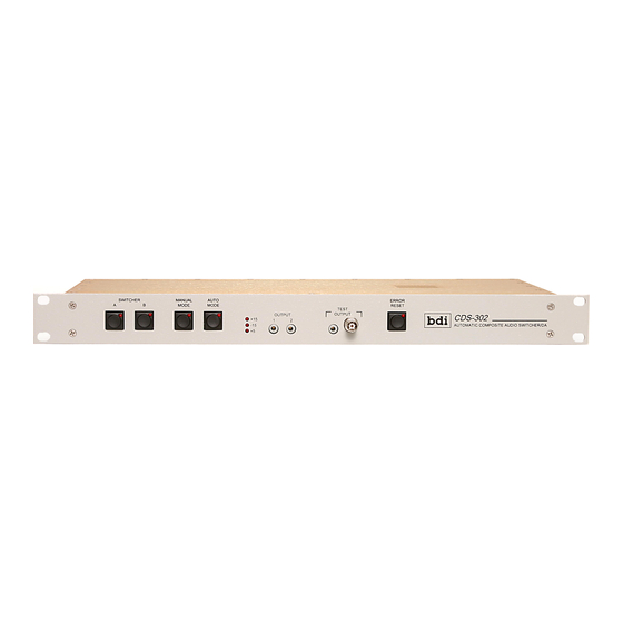
G. Manual Operation To operate the CDS-302 in manual, simply depress the “manual” button on the front panel. The unit will function as a manual switcher taking commands from the front panel switcher buttons or from the remote control connector. -
Page 7: Warranty
Broadcast Devices, Inc. factory at Cortlandt Manor, New York. The office may suggest further tests or authorize return for factory evaluation. -
Page 8: Schematic Diagrams
V. Schematic Diagrams A. Schematic Diagram... - Page 9 LEDERR NOTE: ALL RELAYS SHOWN IN "POWER OFF" STATE AUTOENSW AUTODEFSW AUTOENLED AUTODEFLED 1.3K 1/4W 49.9 1/4W HDR16DUAL BUF634 Broadcast Devices, Inc. FRONT PANEL INTERFACE Title CDS-300 MAIN BOARD 1K 1/4W .1 50V Size Document Number +15V 4.7uF 50V Date:...
Need help?
Do you have a question about the CDS-302 and is the answer not in the manual?
Questions and answers