Table of Contents
Advertisement
Quick Links
Service
Manual
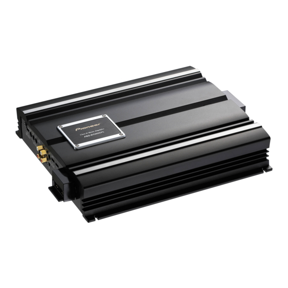
CLASS D MONO AMPLIFIER
PRS-D5000SPL
PRS-D5000SPL
For details, refer to "Important check points for good servicing".
PIONEER CORPORATION
PIONEER ELECTRONICS (USA) INC.
PIONEER EUROPE NV
Haven 1087 Keetberglaan 1, 9120 Melsele, Belgium
PIONEER ELECTRONICS ASIACENTRE PTE.LTD. 253 Alexandra Road, #04-01, Singapore 159936
C PIONEER CORPORATION 2004
PRS-D5000SPL/X1H/EW
4-1, Meguro 1-Chome, Meguro-ku, Tokyo 153-8654, Japan
P.O.Box 1760, Long Beach, CA 90801-1760 U.S.A.
/X1H/UC
K-ZZB. SEPT. 2004 Printed in Japan
ORDER NO.
CRT3326
/X1H/EW
Advertisement
Table of Contents

Summary of Contents for Pioneer PRS-D5000SPL
- Page 1 PIONEER ELECTRONICS (USA) INC. P.O.Box 1760, Long Beach, CA 90801-1760 U.S.A. PIONEER EUROPE NV Haven 1087 Keetberglaan 1, 9120 Melsele, Belgium PIONEER ELECTRONICS ASIACENTRE PTE.LTD. 253 Alexandra Road, #04-01, Singapore 159936 C PIONEER CORPORATION 2004 K-ZZB. SEPT. 2004 Printed in Japan...
-
Page 2: Safety Information
Health & Safety Code Section 25249.6 - Proposition 65 - Service Precaution You should conform to the regulations governing the product (safety, radio and noise, and other regulations), and should keep the safety during servicing by following the safety instructions described in this manual. PRS-D5000SPL/X1H/EW... - Page 3 To protect products from damages or failures during transit, the shipping mode should be set or the shipping screws should be installed before shipment. Please be sure to follow this method especially if it is specified in this manual. PRS-D5000SPL/X1H/EW...
-
Page 4: Table Of Contents
2. EXPLODED VIEWS AND PARTS LIST ......6 7. GENERAL INFORMATION........25 2.1 PACKING..............6 7.1 DIAGNOSIS ............25 2.2 EXTERIOR ............8 7.1.1 DISASSEMBLY.........25 3. SCHEMATIC DIAGRAM...........10 7.1.2 ..26 CONNECTOR FUNCTION DESCRIPTION 3.1 SCHEMATIC DIAGRAM (GUIDE PAGE) ...10 8. OPERATIONS ............27 4. PCB CONNECTION DIAGRAM........16 4.1 AMP UNIT............16 PRS-D5000SPL/X1H/EW... -
Page 5: Specifications
• Specifications and the design are subject to possible modification without notice due to improvements. *Average current drawn • The average current drawn is nearly the maximum current drawn by this unit when an audio signal is input. Use this value when working out total current drawn by multiple power amplifiers. PRS-D5000SPL/X1H/EW... -
Page 6: Exploded Views And Parts List
2. EXPLODED VIEWS AND PARTS LIST 2.1 PACKING 11(1/2) 11(2/2) PRS-D5000SPL/X1H/EW... - Page 7 11(1/2) Fuse Holder (Base) HKR1026 11(2/2) Fuse Holder (Cover) HKR1026 12 Install Card (EW) HRP1298 Install Card (UC) HRP1297 13 Polyethylene Bag HEG0031 - Owner's Manual Part No. Language HRD0240 English, French HRD0241 English, Spanish, German, French, Italian, Dutch PRS-D5000SPL/X1H/EW...
-
Page 8: Exterior
2.2 EXTERIOR PRS-D5000SPL/X1H/EW... - Page 9 HKF0001 39 Terminal(CN609) HKF0001 40 Terminal(CN610) HKF0001 41 Terminal(CN611) HKF0001 42 Terminal(CN612) HKF0001 43 Clip HNC0054 44 Buss Bar HNC0200 45 Buss Bar HNC0201 46 Insulator HNM0208 47 Screw PPZ30P100SAD 48 Light Pipe HXA0426 49 Terminal Unit (CN301,302) HXA0448 PRS-D5000SPL/X1H/EW...
-
Page 10: Schematic Diagram
> > > > > > > > > > The > mark found on some component parts indicates the importance of the safety factor of the part. Therefore, when replacing, be sure to use parts of identical designation. PRS-D5000SPL/X1H/EW... - Page 11 Decimal points for resistor No differentiation is made between chip resistors and and capacitor fixed values discrete resistors. are expressed as : ← Symbol indicates a capacitor. ← No differentiation is made between chip capacitors and 0.022 R022 discrete capacitors. PRS-D5000SPL/X1H/EW...
- Page 12 PRS-D5000SPL/X1H/EW...
- Page 13 PRS-D5000SPL/X1H/EW...
- Page 14 PRS-D5000SPL/X1H/EW...
- Page 15 PRS-D5000SPL/X1H/EW...
-
Page 16: Pcb Connection Diagram
1.The parts mounted on this PCB Capacitor Connector include all necessary parts for AMP UNIT several destination. For further information for SIDE A respective destinations, be sure to check with the schematic dia- gram. SIDE B Chip Part P.C.Board PRS-D5000SPL/X1H/EW... - Page 17 SIDE A MODE SELECT GAIN CONTROL BASS BOOST FREQ. BASS BOOST LEVEL SYNC SYNC OUTPUT INPUT INPUT INPUT LPF FREQ. SLOPE SELECT SUBSONIC SELECT SPEAKER OUTPUT PRS-D5000SPL/X1H/EW...
- Page 18 AMP UNIT PRS-D5000SPL/X1H/EW...
- Page 19 SIDE B PRS-D5000SPL/X1H/EW...
-
Page 20: Electrical Parts List
RD3R9E(B1) Transistor IRF640N Diode 1SS133 Transistor IRF640N Diode 1SS133 Transistor IRF640N Diode FML22S Transistor IRF640N Diode FML22S Transistor DTC124EK Diode FML22S Transistor DTA124EK Diode RD39EB Transistor DTA124EK Diode RD9R1E(B2) Transistor DTC124EK Diode RD9R1E(B2) Transistor KSC1623 Diode RD39EB Transistor 2SA1048 PRS-D5000SPL/X1H/EW... - Page 21 Variable Resistor 10kΩ(A) CCS1265 RS1/2PMF221J (GAIN CONTROL) RS1/2PMF221J Semi-fixedr 2.2kΩ HCP0003 RS1/2PMF241J Semi-fixed 100kΩ(B) RH063MC15R RD1/4PU100J Semi-fixed 100kΩ(B) RH063MC15R RD1/4PU100J > Fuse 30A HEK0041 RS1/16S510J > Fuse 30A HEK0041 RS1/16S470J > Fuse 30A HEK0041 RS2LMF301J RS2LMF301J RS2LMF221J RS2LMF221J RS1/2PMF4R7J PRS-D5000SPL/X1H/EW...
- Page 22 RD1/4PU152J RS1/16S2401D RD1/4PU152J RS1/16S2401D (EW) RS1/16S105J RS1/16S433J RS1/16S183J RS1/16S433J RS1/16S102J RS1/16S103J RS1/16S273J RS1/16S163J RD1/4PU0R0J RS1/16S104J RS1/16S242J RS1/16S272J RS1/16S472J RD1/4PU151J RS1/16S472J RS1/2PMF220J RS1/16S272J RS1/2PMF220J RS1/16S272J RD1/4PU153J RS1/16S272J RD1/4PU153J RD1/4PU621J RD1/4PU333J RD1/4PU621J RD1/4PU333J RD1/4PU621J RS1/16S471J RD1/4PU621J RS1/16S223J RD1/4PU472J RN1/10SE1002D RD1/4PU472J RN1/10SE1002D PRS-D5000SPL/X1H/EW...
- Page 23 CFTNA103J50 CFTNA103J50 CKSRYB472K50 CQMA472J50 CFTNA103J50 4700µF/25V HCH0022 CEAT100M16 4700µF/25V HCH0022 CEATR47M50 4700µF/25V HCH0022 CEAT471M16 CEAT100M50 CQMA472J50 CQMA472J50 CEAT100M50 4700µF/25V HCH0022 CEAT100M50 4700µF/25V HCH0022 CEAT100M50 4700µF/25V HCH0022 CEAT100M50 CEAT1R0M50 CQMA472J50 CFTNA103J50 CEAT1R0M50 220µF/10V HCH0012 CEATR22M50 CFTNA473J50 CEAT1R0M50 CFTNA223J50 CKSRYB223K25 CKSRYB103K50 PRS-D5000SPL/X1H/EW...
-
Page 24: Adjustment
CKSRYB332K50 CEAT470M25 CKSRYB272K50 0.1µF HCE0003 CKSRYB272K50 0.1µF HCE0003 CFTNA103J50 CFTNA104J50 CFTNA103J50 CFTNA104J50 220µF/10V HCH0012 CFTNA334J50 220µF/35V HCH0032 220µF/35V HCH0032 CEAT100M50 CEAT100M50 3300pF HCH0029 3300pF HCH0029 3300pF HCH0029 6. ADJUSTMENT There is no information to be shown in this chapter. PRS-D5000SPL/X1H/EW... -
Page 25: General Information
Remove the five screws and then remove the Panel. Remove the two screws. Remove the two screws and then remove the Panel. Remove the seventeen screws. Remove the fifteen screws and then remove the Amp Unit. Amp Unit Panel Fig.2 PRS-D5000SPL/X1H/EW... -
Page 26: Connector Function Description
7.1.2 CONNECTOR FUNCTION DESCRIPTION PRS-D5000SPL/X1H/EW... -
Page 27: Operations
8. OPERATIONS PRS-D5000SPL/X1H/EW...


Need help?
Do you have a question about the PRS-D5000SPL and is the answer not in the manual?
Questions and answers