
Related Manuals for LG GN-332


Summary of Contents for LG GN-332
- Page 1 REFRIGERATOR SERVICE MANUAL CAUTION BEFORE SERVICING THE UNIT, READ THE "SAFETY PRECAUTIONS" IN THIS MANUAL. Ref. No. GR-332 MODEL: GN-332 COLOR: ALL COLOUR...
-
Page 2: Table Of Contents
CONTENTS SAFETY PRECAUTIONS ............................... 2 SERVICING PRECAUTIONS..............................3 SPECIFICATIONS................................... 4 PARTS IDENTIFICATION ............................... 5 DISASSEMBLY..................................6-7 DOOR....................................6 DOOR SWITCH..................................6 THERMOSTAT ..................................6 FAN AND FAN MOTOR................................ 6 DEF' CONTROL ASM ................................7 REFRIGERATOR ROOM LAMP ............................7 CONTROL BOX-R................................7 REPLACEMENT OF DOOR OPENING TYPE........................8-9 ADJUSTMENT ................................. -
Page 3: Servicing Precautions
SERVICING PRECAUTIONS AIR RECHARGING IN COMPRESSOR vacuum operation is over, add the quantity in grams of R-134a to the refrigeration system. Remember that every Test the refrigeration system connecting it electrically before system has an exact quantity of R-134a with a tolerance of refilling operation. -
Page 5: Parts Identification
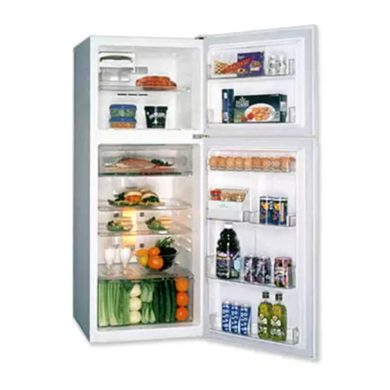
2. PARTS IDENTIFICATION FREEZER COMPARTMENT Freezer Temperature Control Dial Wine Rack(Option) Ice Trays Freezer Shelf Freezer Door Rack (Plastic or Steel) Twisting Ice Serve(Option) General Type Ice Making REFRIGERATOR Egg Storage Rack COMPARTMENT Deodorizer (Option) Dairy Corner (Option) Chilled Room Temperature Movable Rack Control Dial... -
Page 6: Disassembly
3. DISASSEMBLY 3-1 DOOR 3-2 DOOR SWITCH Freezer Door 1. To remove the door switch, pull out it with a '—' type 1. Remove the hinge cover by pulling it upwards. driver as shown in (figure 9). 2. Loosen hexagonal bolts fixing the upper hinge to the 2. -
Page 7: Def' Control Asm
6. Disconnect the housing of lead wire. 3-6 REFRIGERATOR ROOM LAMP 7. Separate the Fan Assy. 1. Remove the cover lamp-R by pulling with a '–––' type 8. Loose 2 screw fixed to the Bracket. driver. 9. Pull out Shroud-F remove the Fan Motor Assy. 2. -
Page 8: Replacement Of Door Opening Type
3-8 REPLACEMENT OF DOOR OPENING TYPE - Converting Door is Optional Precaution 1. Before replacing the door opening type, first of all, you should take out foodstuffs and accessories like shelves or trays, and so on which are not fixed in the refrigerator. - Page 9 Assemble the Hinge Lower ² . Move the Position of Adjustable Screw Assembly ¶ . Move the Cap º , Bracket ¾ of the Refrigerator Move the Cap µ and Assemble the Hinge-C ¸ . Door. After removing the washer. Assembe the Door Stopper-F ¸...
-
Page 10: Adjustment
4. ADJUSTMENT 4-1 COMPRESSOR 4-2-3 PTC-Applied Circuit Diagram According to Starting Method of Motor 4-1-1 Role The compressor inhales low temperature and low pressure OVERLOAD PROTECTOR gas evaporated from Evaporator of the Refrigerator, and condenses this gas to high temperature and high pressure gas, and then plays delivering role to Condenser. -
Page 11: Olp (Overload Protector)
4-3 OLP (OVERLOAD PROTECTOR) CONTACTING POINT 4-3-1 Definition of OLP COVER (1) OLP (OVERLOAD PROTECTOR) is attached to the Compressor and protects the Motor by cutting the BIMETAL current to the Motor if the temperature rises and activates the bimetal spring in the OLP. CONTACTING (2) When over-voltage flows to Compressor motor, the POINT... -
Page 12: Troubleshooting
6. TROUBLESHOOTING 6-1 COMPRESSOR AND ELECTRIC COMPONENTS (Rating Voltage Remove the PTC-Starter Power Source. ±10%)? from the Compressor and measure the voltage between Terminal C of Compressor and Terminals 5 or 6 of PTC. No Voltage. OLP disconnected? Replace OLP. Check connection condition. -
Page 13: Ptc And Olp
6-2 PTC AND OLP Check another Normal operation of Separate the PTC from Observation value is 220V/50Hz : 22 Ω ±30% electric components. Compressor is Compressor and 115V/60Hz : 6.8 Ω ±30% impossible or poor. measure the resistance 240V/50Hz : 33 Ω ±30% between No. -
Page 14: Another Electric Component
6-4 ANOTHER ELECTRIC COMPONENTS Cooling is impossible Check if current flows to Compressor Cause the following doesn't run. components. Poor contacting and a. Thermostat gas leakage. b. Starting devices Shorted or broken. Poor contacting c. OLP or shorted. d. Compressor coil Coil shorted. -
Page 15: Service Diagnosis Chart
6-5 SERVICE DIAGNOSIS CHART COMPLAINT POINTS TO BE CHECKED REMEDY Cooling is • Is the power cord unplugged from the outlet? • Plug to the outlet. impossible. • Check if the power S/W is setted to OFF. • Set the switch to ON. •... -
Page 16: Refrigerating Cycle
6-6 REFRIGERATING CYCLE Troubleshooting Chart TEMPERATURE STATE OF STATE OF THE CAUSE REMARKS OF THE THE SET EVAPORATOR COMPRESSOR PARTIAL Freezer and Low flowing sound of A little high • A little Refrigerant LEAKAGE Refrigerator Refrigerant is heard and more than •... - Page 17 General Control of Refrigerating Cycle ITEMS UNIT STANDARDS PURPOSES REMARKS Pipe and Min. Pipe: within 1 hour. To protect The opening time should be reduced piping system Comp: within 10 minutes. moisture to a half of the standards during rain opening time Drier: within 20 minutes.
-
Page 18: Exploded View
281A 103B 281B 301A 103A 401A 501F 501A 411A 281D 418A 416A 125L 410G 282B 410H 129A 501K 406B 410B 410C 410J 410A 304A 604E 604F 120A 120E 120B 105A 120C 409B 317A 318A 409C 307A 310A 283B 314A 308A 106A 309A 329D... - Page 19 405C 405A 330B 404A 329A 200A 203A 205A 201A 332A 212G 205A 110B 125A 131A 125H 125J 149A 149D 149A 243A 235A 210A 241A 230A 149B 233A 140A 231A 249A 149C 149C 149C 241B 149C 237A 154A 241C 241D 243A 151A...
- Page 20 P/No. 3828JD8323J FEB., 2006 Printed in Korea...
Need help?
Do you have a question about the GN-332 and is the answer not in the manual?
Questions and answers