Table of Contents
Advertisement
Quick Links
REV.5
RS.3
ADVANCED REMOTE STARTER
INSTALLATION GUIDE
www.security.soundstream.com
FCC ID NOTICE
This device complies with Part 15 of the FCC rules. Operation is subject to the following conditions:
1. This device may not cause harmful interference, and
2. This device must accept any interference received, including interference that may cause undesired operation.
CAUTION: Changes or modifications not expressly approved by the part responsible for compliance void the user's authority to operate
this device.
Advertisement
Table of Contents

Related Manuals for Soundstream Tarantula RS.3


Summary of Contents for Soundstream Tarantula RS.3
- Page 1 REV.5 RS.3 ADVANCED REMOTE STARTER INSTALLATION GUIDE www.security.soundstream.com FCC ID NOTICE This device complies with Part 15 of the FCC rules. Operation is subject to the following conditions: 1. This device may not cause harmful interference, and 2. This device must accept any interference received, including interference that may cause undesired operation.
-
Page 2: Table Of Contents
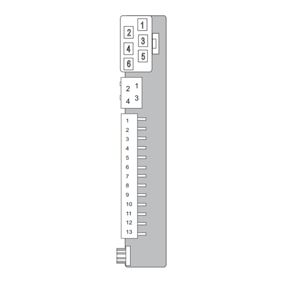
RS.3 PAGE 2 INSTALL MANUAL SYSTEM PROGRAMMING - Menu 1 TABLE OF CONTENTS QUICK VIEW WIRING DIAGRAM............3-4 Connector Pin Configuration Antenna Connector Park Light Jumper INSTALLATION NOTES................5 TACH LEARNING..................6 Data Tach Mode Tach/ Tachless Learn Hybrid Mode QUICK VIEW PROGRAMMING..............7-9... - Page 3 RS.3 PAGE 3 QUICK VIEW WIRE DIAGRAM INSTALL MANUAL SYSTEM PROGRAMMING - Menu 1 OUTPUT TO ACTIVATE THE STARTER CIRCUIT PURPLE OUTPUT TO ACTIVATE ACCESSORY CIRCUIT ORANGE 12VOLT/ 30 AMP MAIN POWER INPUT 12VOLT/ 30 AMP MAIN POWER INPUT SELECTABLE OUTPUT* (DEFAULT 2ND IGN)
-
Page 4: Park Light Jumper
RS.3 PAGE 4 INSTALL MANUAL SYSTEM PROGRAMMING - Menu 1 QUICK VIEW WIRE DIAGRAM OUTPUT TO ACTIVATE DOOR LOCK CIRCUIT (-) GREEN OUTPUT FOR VOLTAGE INVERTER* N/A* OUTPUT TO ACTIVATE DOOR UNLOCK CIRCUIT (-) BLUE NOT USED (-) WHILE RUNNING OUTPUT (BYPASS TURN ON) - Page 5 RS.3 PAGE 5 NOTES INSTALL MANUAL SYSTEM PROGRAMMING - Menu 1 PLEASE NOTE * THE CENTRE PIN OF THE KEYLESS CONNECTOR IS LOW CURRENT AND IS DESIGNED TO SUPPLY POWER TO DOOR LOCK MODULES (DO NOT CONNECT TO RELAYS) OVERLOADING THIS OUTPUT WILL DAMAGE THE MODULE! **THIS CONNECTOR IS USED FOR THE ARS .1 ALARM MODELS ONLY.
-
Page 6: System Wiring Details
RS.3 PAGE 6 INSTALL MANUAL SYSTEM PROGRAMMING - Menu 1 SYSTEM WIRING DETAILS AUTO TACH/ TACHLESS LEARNING 2 HONKS/ 2 FLASHES = TACH MODE Start the vehicle with 3 HONKS/ 3 FLASHES = DATA TACH MODE the ignition key. 4 HONKS/ 4 FLASHES = TACHLESS MODE NOTES: When tach learning the system first sends out a request for tach from the data port. -
Page 7: System Reset
RS.3 PAGE 7 PROGRAM MODE INSTALL MANUAL SYSTEM PROGRAMMING - Menu 1 ENTERING PROGRAM MODE 1 - Cycle the Ignition Key On/Off On/Off On (Leaving the key ON) 2 - Press and release the Program Switch 1 time. The park lights will turn on and the Horn will Honk to confirm entering program mode. - Page 8 RS.3 PAGE 8 INSTALL MANUAL PROGRAM MODE SYSTEM PROGRAMMING - Menu 1 PROGRAM MODE 1 (1 Flash/ 1 Honk) SETTING # SETTING OPTION 1 OPTION 2 OPTION 3 LED FLASHES DESCRIPTION 1 HONK 2 HONKS 3 HONKS IGNITION IGNITION AUTO-LOCK /...
- Page 9 RS.3 PAGE 9 PROGRAM MODE INSTALL MANUAL SYSTEM PROGRAMMING - Menu 1 SYSTEM PROGRAMMING - Menu 1 PROGRAM MODE 3 (3 Flashes/ 3 Honks) SETTING # SETTING OPTION 1 OPTION 2 OPTION 3 DESCRIPTION 1 HONK 2 HONKS 3 HONKS...
-
Page 10: Purple
RS.3 PAGE 10 INSTALL MANUAL SYSTEM PROGRAMMING - Menu 1 SYSTEM WIRING DETAILS 6-PIN CONNECTOR OUTPUT TO ACTIVATE START CIRCUIT PURPLE OUTPUT TO ACTIVATE ACCESSORY/ HEATER CIRCUIT ORANGE 30A HIGH CURRENT 12VOLT INPUT 30A HIGH CURRENT 12VOLT INPUT SELECTABLE OUTPUT (DEFAULT SECOND IGNITION) - Page 11 RS.3 PAGE 11 SYSTEM WIRING DETAILS INSTALL MANUAL SYSTEM PROGRAMMING - Menu 1 PIN-1 PURPLE Starter Output-This wire will test 0V when the key is off, in the Accessory position and when the Ignition is in the on position. The starter wire is 12volts during the start/ crank position only.
-
Page 12: Green/White
RS.3 PAGE 12 INSTALL MANUAL SYSTEM PROGRAMMING - Menu 1 SYSTEM WIRING DETAILS 13 PIN CONNECTOR OUTPUT FOR FACTORY ALARM RE-ARM GREEN/WHITE OUTPUT FOR FACTORY ALARM DIS-ARM GREEN/BLACK NEGATIVE STARTER OUTPUT PINK/WHITE OUTPUT FOR TRUNK RELEASE ACTIVATION RED/WHITE NEGATIVE ACCESSORY OUTPUT/ AUXILIARY OUTPUT 2... -
Page 13: Gray/Black
RS.3 PAGE 13 SYSTEM WIRING DETAILS INSTALL MANUAL SYSTEM PROGRAMMING - Menu 1 1-GREEN/WHITE Re-arm(-) (Programmable) - Supplies one .75 second pulse when locked and one .75 second pulse after remote start shutdown. Factory alarm re-arm/ RAP shutdown. 2-GREEN/BLACK Dis-arm(-) - .75 second pulse when unlock button is pressed and one .75 second pulse before remote start activation. - Page 14 RS.3 PAGE 14 INSTALL MANUAL SYSTEM PROGRAMMING - Menu 1 SYSTEM WIRING DETAILS 3 PIN BYPASS CONNECTOR GROUND WHEN RUNNING OUTPUT ORANGE GROUND OUTPUT BLACK 1- ORANGE Wire- Ground When Running (-) Connect this wire to the your bypass modules negative turn on wire. When the remote starter is activated this wire will switch to ground.
-
Page 15: Installer Notes
RS.3 PAGE 15 INSTALLER NOTES INSTALL MANUAL SYSTEM PROGRAMMING - Menu 1... -
Page 16: Transmitter Programming
RS.3 PAGE 16 INSTALL MANUAL SYSTEM PROGRAMMING - Menu 1 TRANSMITTER PROGRAMMING PROGRAMMING ADDITIONAL TRANSMITTERS The system can lean up to 4 different remote’s. Each remote to be used MUST be programmed together during the same sequence. For security, when a new remote is programmed all previous remote’s are deleted. -
Page 17: Diagnostics
RS.3 PAGE 17 DIAGNOSTICS INSTALL MANUAL SYSTEM PROGRAMMING - Menu 1 DIAGNOSTICS CHART If the remote starter does not activate when the start button is pressed the park lights will flash a diagnostic to indicate what shutdown input has been triggered. For example: If the start button is pressed the park lights flash 3 times slowly. -
Page 18: Door Lock Diagrams
RS.3 PAGE 18 INSTALL MANUAL RELAY DIAGRAMS DOOR LOCK DIAGRAMS Vehicle's Lock/Unlock Switch Door lock Output To Control Relay or Actuators Green Blue Ground Vehicle's Lock/ Unlock Switch Door lock Output 12volts Green Blue Ground 12volts USE SPDT 12v Relay... -
Page 19: Door Lock Diagrams
RS.3 PAGE 19 RELAY DIAGRAMS INSTALL MANUAL SYSTEM PROGRAMMING - Menu 1 DOOR LOCK DIAGRAMS Ground Vehicle's Lock/ Unlock Switch Door lock Output 12volts Green Blue Ground Lock Resistor 12volts Unlock Resistor USE SPDT 12v Relay 12volts Lock/ Unlock Switch... - Page 20 www.security.soundstream.com...
Need help?
Do you have a question about the Tarantula RS.3 and is the answer not in the manual?
Questions and answers