Table of Contents
Advertisement
Quick Links
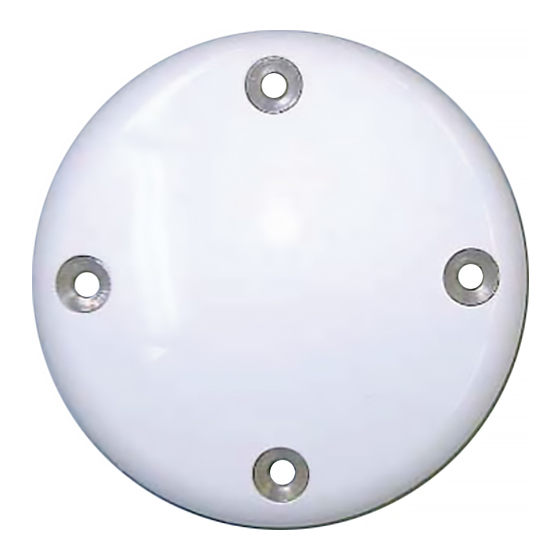
ANT-35C1GLA-TRW Antenna
USER GUIDE
OM-20000133
Rev 1
April 2012
The ANT-35C1GLA-TRW antenna is designed for airborne use,
but works in any mobile application.
The ANT-35C1GLA-TRW is an
active GPS antenna, 88.9 mm (3.5-
inches) in diameter and operates at
the GPS L1 1575.42 MHz frequency
and the L-Band 1525-1560
frequencies. The antenna is a
spherical radius molded radome that
provides enhanced protection
against rain and ice.
The antenna includes the following:
•
internal 33 dB low noise amplifier
•
bias voltage from 2.5-24 V DC for operation
•
band pass filtering
•
DC bias provided through the coaxial connector
NovAtel offers optional coaxial cables in various lengths to
connect the antenna and NovAtel GNSS receivers.
The ANT-35C1GLA-TRW is aircraft certified for navigation. This
guide provides the basic information you need to install and
begin using your new antenna.
ADDITIONAL EQUIPMENT REQUIRED
•
A device with an antenna input port that both receives
the RF signal and provides 2.5 - 24.0 VDC to the
antenna is required for the ANT-35C1GLA-TRW.
NovAtel GPS receivers provide the necessary power
through their antenna RF connectors.
•
Coaxial cable with a male TNC connector
INSTALLING THE ANTENNA
Both the input DC power and the output RF signal use a single
coaxial cable connected to the unit's TNC female connector.
The antenna attaches to a surface with a square, four bolt, 1.9-
inch space mounting pattern as shown in the Mechanical
Drawings section of this guide. Four screws pass through the
antenna housing.
To install the antenna:
1. Install the supplied gasket on the antenna base.
2. Pre-drill and tap the mounting holes and drill the connector
clearance hole on the mounting surface. See the Mechanical
Drawings section for mounting pattern details.
3. Use the four supplied mounting screws to attach the antenna
to the mounting surface. The gasket compresses and cre-
ates a seal between the surface and the antenna.
Note: NovAtel recommends thread-locker (not included) on the
mounting screws.
2
1
5
3
4
Ref. #
Description
Ref.#
Description
1
Antenna
4
gasket
2
Countersink screws
5
Pre-drilled mounting holes
3
Mounting surface
4. Remove the dust cap from the antenna's TNC connector.
5. Attach the coaxial cable's male TNC connector to the
antenna's TNC connector.
Ref.# Description
1
Mounted antenna
2
Mounting surface
3
TNC connector
4
Coaxial cable
6. Attach the other end of the coaxial cable to the antenna input
port on the receiving device. The receiving device must be
equipped to provide power as detailed in the
Specifications section of this guide. All NovAtel GPS
receivers provide the necessary power through the antenna
RF connectors.
This graphic provides examples of where the antenna may be
located on an aircraft or vehicle (not to scale).
ANTENNA CARE
The ANT-35C1GLA-TRW is designed to withstand the elements,
including rain, snow and dust. However, to ensure that the
antenna performs optimally, keep the radome clean and brush
off any ice or snow. In addition, ensure the TNC connector
remains clean and dry and replace the dust cap when a cable is
not connected.
Advertisement
Table of Contents

Related Manuals for Novatel ANT-35C1GLA-TRW


Summary of Contents for Novatel ANT-35C1GLA-TRW
- Page 1 The antenna attaches to a surface with a square, four bolt, 1.9- Ref.# Description inch space mounting pattern as shown in the Mechanical Mounted antenna The ANT-35C1GLA-TRW antenna is designed for airborne use, Drawings section of this guide. Four screws pass through the Mounting surface but works in any mobile application.
- Page 2 If you need any further advice on this matter, please visit our There are no user-serviceable parts in the GPSAntenna and no maintenance is required. If the unit is faulty, replace with another unit and return the faulty unit to NovAtel Inc. You must Input voltage 2.5 - 24.0 VDC...
Need help?
Do you have a question about the ANT-35C1GLA-TRW and is the answer not in the manual?
Questions and answers