Table of Contents
Advertisement
SERVICE MANUAL
Ver. 1.1 2007.08
CD player section
System
Compact disc digital audio system
Laser diode properties
Emission duration: Continuous
Laser output: Less than 44.6 µW
(This output is the value measured at a distance of about 200 mm from
the objective lens surface on the optical pick-up block with 7 mm
aperture.)
Number of channels
2
Frequency response
20 - 20 000 Hz +1/−1 dB
Wow and flutter
Below measurable limit
Radio section
Frequency range
FM: 87.5 - 108 MHz
AM:
except Mexican model:
531 - 1 611 kHz (9 kHz step)
530 - 1 610 kHz (10 kHz step)
Mexican model:
530 - 1 710 kHz
IF
FM: 10.7 MHz
AM: 450 kHz
Antennas
FM: Telescopic antenna
AM: Built-in ferrite bar antenna
General
Speaker
Full range: 10 cm dia., 6 Ω, cone type (2)
Input
AUDIO IN jack (stereo minijack): Minimum input level 245 mV
Outputs
Headphones jack (stereo minijack)
For 16 - 64 Ω impedance headphones
Sony Corporation
9-887-662-02
Personal Audio Division
2007H05-1
Published by Sony Techno Create Corporation
© 2007.08
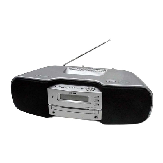
ZS-S50CP
Model Name Using Similar Optical Pick-up Block
Optical Pick-up Block Type
SPECIFICATIONS
Power output
4.5 W + 4.5 W (at 6 Ω, 10% harmonic distortion)
Power requirements
For player:
Mexican model: 120 V AC, 60 Hz
Singapore model: 230 - 240 V AC, 50 Hz
Other models: 230 V AC, 50 Hz
9 V DC, 6 R20 (size D) batteries
For remote control:
3 V DC, 2 R6 (size AA) batteries
Power consumption
AC 16 W
Battery life
For player:
FM Radio reception
Sony R20P: approx. 30 h
Sony alkaline LR20: approx. 60 h
CD playback
Sony R20P: approx. 8 h
Sony alkaline LR20: approx. 20 h
It is recommended that you use alkaline batteries.
Dimensions
Approx. 480 × 156 × 250 mm (w/h/d)
(incl. projecting parts)
Mass
Approx. 4.3 kg (incl. batteries)
Supplied accessories
AC power cord (1)
Remote control (1)
Design and specifications are subject to change without notice.
PERSONAL AUDIO SYSTEM
AEP Model
E Model
NEW
KSM-213CCP
Advertisement
Table of Contents

Related Manuals for Sony ZS-S50CP


Summary of Contents for Sony ZS-S50CP
- Page 1 Below measurable limit FM Radio reception Sony R20P: approx. 30 h Radio section Frequency range Sony alkaline LR20: approx. 60 h FM: 87.5 - 108 MHz CD playback Sony R20P: approx. 8 h except Mexican model: Sony alkaline LR20: approx. 20 h...
-
Page 2: Table Of Contents
COMPONENTS IDENTIFIED BY MARK 0 OR DOTTED LINE WITH MARK 0 ON THE SCHEMATIC DIAGRAMS AND IN THE PARTS LIST ARE CRITICAL TO SAFE OPERATION. REPLACE THESE COMPONENTS WITH SONY PARTS WHOSE PART NUMBERS APPEAR AS SHOWN IN THIS MANUAL OR IN SUPPLEMENTS PUBLISHED BY SONY. -
Page 3: Servicing Notes
ZS-S50CP SECTION 1 SERVICING NOTES UNLEADED SOLDER NOTES ON HANDLING THE OPTICAL PICK-UP Boards requiring use of unleaded solder are printed with the lead- BLOCK OR BASE UNIT free mark (LF) indicating the solder contains no lead. The laser diode in the optical pick-up block may suffer electrostatic... -
Page 4: General
ZS-S50CP SECTION 2 This section is extracted from instruction manual. GENERAL Basic Operations Changing the AM tuning interval Tips Changing the AM tuning interval Playing a CD/MP3 disc Playback starts from the track/MP3 file you last stopped playing (except Mexican model) If you need to change the AM tuning interval, do the (Resume play). -
Page 5: Other Operations
ZS-S50CP Other Operations Using the display Playing tracks/MP3 files in random Presetting radio stations Connecting optional component order (Shuffle Play) You can check information about the CD using the You can store radio stations into the unit’s memory. You You can enjoy the sound from a PC, TV, VCR, portable display. -
Page 6: Disassembly
ZS-S50CP SECTION 3 DISASSEMBLY • This set can be disassembled in the order shown below. 3-1. DISASSEMBLY FLOW 3-2. CABINET (LOWER) ASSY (Page 7) 3-3. CABINET (UPPER) ASSY 3-4. CD BLOCK (Page 8) (Page 8) 3-5. MAIN BLOCK ASSY 3-9. OPTICAL PICK-UP BLOCK... -
Page 7: Cabinet (Lower) Assy
ZS-S50CP Note: Follow the disassembly procedure in the numerical order given. 3-2. CABINET (LOWER) ASSY 2 three screws (B2.6) 8 foot (felt) Turn the set. 5 six screws (B2.6) 8 foot (felt) 5 six screws (B2.6) 4 battery case lid 9 cabinet (lower) assy 3 Release two hooks. -
Page 8: Cabinet (Upper) Assy
ZS-S50CP 3-3. CABINET (UPPER) ASSY 4 screw (B2.6) 3 two screws (B2.6) 4 screw 5 screw (B2.6) (P2.6 × 10) 5 screw (P2.6 × 10) 7 flexible flat cable (4 core) (CNP810) 8 cabinet (upper) assy 2 telescopic antenna (ANT1) -
Page 9: Main Block Assy
ZS-S50CP 3-5. MAIN BLOCK ASSY 1 connector (CN309) 5 screw (B2.6) 2 connector (CN306) 8 flexible flat cable (11 core) (CNP806) 0 main block assy 5 screw (B2.6) 3 connector (CN902) 7 flexible flat cable (11 core) (CNP802) 4 connector... -
Page 10: Speaker (10 Cm) (Sp101) (L-Ch), Speaker (10 Cm) (Sp201) (R-Ch)
ZS-S50CP 3-7. SPEAKER (10 cm) (SP101) (L-CH), SPEAKER (10 cm) (SP201) (R-CH) 6 speaker (10 cm) (SP201) (R-CH) 5 four screws (B3) 2 speaker box (R) section 3 connector (CN311) 4 Remove two solders. 1 six screws 6 speaker (10 cm) (B2.6) -
Page 11: Optical Pick-Up Block (Ksm-213Ccp)
ZS-S50CP 3-9. OPTICAL PICK-UP BLOCK (KSM-213CCP) 4 optical pick-up block (KSM-213CCP) 1 Remove four solders. 2 flexible flat cable (16 core) (CN301) 7 CD board 6 detection switch (limit) (S201) 5 Remove four solders. 3 screw (BVTT2 × 6) -
Page 12: Test Mode
ZS-S50CP SECTION 4 SECTION 5 TEST MODE ELECTRICAL ADJUSTMENTS COLD RESET CD SECTION Procedure: 1. In the power on status, press three buttons of [ENTER], Note: [POWER] simultaneously. 1. CD Block is basically constructed to operate without adjustment. 2. The set is reset and display “RESET”, then becomes standby 2. - Page 13 ZS-S50CP 0 dB=1 µV TUNER SECTION AM IF ADJUSTMENT Adjust for a maximum reading on level meter [AM] 450 kHz Setting: Function: RADIO ( ): except Mexican model Band: AM AM FREQUENCY COVERAGE ADJUSTMENT Adjustment Part Frequency Display Reading on Digital Voltmeter 1.0 ±...
- Page 14 ZS-S50CP Adjustment and Connecting Location: – TU Board (Component Side) – T2 FM IF Adjustment AM Frequency Coverage Adjustment T1 AM IF Adjustment FM Frequency Coverage Adjustment FM Tracking Adjustment AM Tracking Adjustment – TU Board (Conductor Side) – (VT)
-
Page 15: Diagrams
ZS-S50CP SECTION 6 DIAGRAMS 6-1. BLOCK DIAGRAM – CD SERVO Section – DETECTOR +3.3V FNi1 (A) 97 FPi1 (B) CD-L (Page 17) AGCi RFEQo 81 RFi 94 FNi2 (C) 82 RFRPi R-CH 96 FPi2 (D) RFRP RFZI 100 TNi (E) -
Page 16: Block Diagram - Tuner Section
ZS-S50CP 6-2. BLOCK DIAGRAM – TUNER Section – FM IFT FM/AM RF AMP, MIX, OSC, FM/AM IF AMP, DET, MPX FM IF ANT1 FM TELESCOPIC ANTENNA L-OUT RA-L IF-IN RF-IN MIX-OUT FM IF (Page 17) -OUT RF AMP MUTE BUFFER... -
Page 17: Block Diagram - Main Section
ZS-S50CP 6-3. BLOCK DIAGRAM – MAIN Section – INPUT SELECTOR, ELECTRICAL VOLUME IC302 CD-L L2-IN (Page 15) L1-IN SP201 L4-IN R-CH (R-CH) MEGA BASS CONTROL Q101 SP101 RA-L (Page 16) (L-CH) L-IGOUT L-VOLIN L-OUT POWER AMP J301 IC304 MUTING POWER AMP... -
Page 18: Block Diagram - Power Supply Section
ZS-S50CP 6-4. BLOCK DIAGRAM – POWER SUPPLY Section – AMP B+ +3.3V B+ SWITCH SYS +3.3V REGULATOR Q814, 815 IC801 B+ SWITCH LCD +3.3V Q807, 812 LCD-VDDON 3 B+ SWITCH RMC +3.3V Q808, 809 BATCHK-H 43 REG6V-CHK 38 REG3V-CHK 39 +1.5V... - Page 19 ZS-S50CP Ver. 1.1 • Note for Printed Wiring Boards and Schematic Diagrams • Circuit Boards Location Note on Printed Wiring Board: Note on Schematic Diagram: KEY (TOP-L) board • X : parts extracted from the component side. • All capacitors are in µF unless otherwise noted. (p: pF) MAIN board •...
-
Page 20: Printed Wiring Boards - Cd Section
ZS-S50CP • See Page 19 for Circuit Boards Location. 6-5. PRINTED WIRING BOARDS – CD Section – : Uses unleaded solder. CD BOARD (CONDUCTOR SIDE) CD BOARD (COMPONENT SIDE) M401 (SPINDLE) S201 (LIMIT) C403 C404 R402 IC401 TP124 M402 (VC) -
Page 21: Schematic Diagram - Cd Board
ZS-S50CP • See Page 31 for Waveforms. • See Page 34 for IC Block Diagrams. • See Page 37 for IC Pin Function Description. 6-6. SCHEMATIC DIAGRAM – CD Board – (BX5BT/CBX1) R127 R126 C107 C136 R125 R120 R142 R139... -
Page 22: Printed Wiring Board - Tu Board
ZS-S50CP • See Page 19 for Circuit Boards Location. 6-7. PRINTED WIRING BOARD – TU Board – : Uses unleaded solder. TU BOARD AM FERRITE-ROD ANTENNA ANT1 FM TELESCOPIC ANTENNA (VT) (ANT) JW14 (GND) (MX) JC24 (EXCEPT MX) (SHIELD CASE) -
Page 23: Schematic Diagram - Tu Board
ZS-S50CP • See Page 31 for Waveforms. • See Page 34 for IC Block Diagrams. 6-8. SCHEMATIC DIAGRAM – TU Board – AM FERRITE-ROD KV1520NT 220p AM OSC ANTENNA AM FREQUENCY 100p COVERAGE (EXCEPT MX) (MX) JC24 JC12 JC11 1µH 0.01... -
Page 24: Printed Wiring Boards - Jack Section
ZS-S50CP Ver. 1.1 • See Page 19 for Circuit Boards Location. 6-9. PRINTED WIRING BOARDS – JACK Section – : Uses unleaded solder. J302 AUDIO IN SP101 SP201 (L-CH) (R-CH) JACK (AU IN) BOARD JACK (HP) BOARD D307 D306 L301... -
Page 25: Printed Wiring Board - Main Board
ZS-S50CP Ver. 1.1 6-10. PRINTED WIRING BOARD – MAIN Board – • See Page 19 for Circuit Boards Location. : Uses unleaded solder. • Semiconductor (Page 28) (Page 29) (Page 28) Location LCD BOARD KEY (TOP-L) BOARD LCD BOARD FFC401... -
Page 26: Schematic Diagram - Main Section (1/2)
ZS-S50CP Ver. 1.1 • See Page 34 for IC Block Diagrams. 6-11. SCHEMATIC DIAGRAM – MAIN Section (1/2) – (1/2) CN310 D306 D307 KH310 1SS355TE-17 1SS355TE-17 CN309 C144 C145 D301 470p 470p C306 L CH L CH L101 47µH J302... -
Page 27: Schematic Diagram - Main Section (2/2)
ZS-S50CP Ver. 1.1 • See Page 31 for Waveforms. • See Page 34 for IC Block Diagrams. • See Page 37 for IC Pin Function Description. 6-12. SCHEMATIC DIAGRAM – MAIN Section (2/2) – (2/2) CNP802 R973 B MUTE C813... -
Page 28: Printed Wiring Board - Lcd Board
ZS-S50CP Ver. 1.1 • See Page 19 for Circuit Boards Location. 6-13. PRINTED WIRING BOARD – LCD Board – : Uses unleaded solder. S401 S401, 404, 405, 408 LCD BOARD Q402 L401 AUDIO IN S404 R441 JW401 R443 C401 JW402... -
Page 29: Printed Wiring Boards - Key Section
ZS-S50CP Ver. 1.1 • See Page 19 for Circuit Boards Location. 6-14. PRINTED WIRING BOARDS – KEY Section – : Uses unleaded solder. PANEL (TOP) BOARD S402, 403, 407, S409 – 422 /PRESET DISPLAY REPEAT MODE M > TUNE –... -
Page 30: Schematic Diagram - Panel Section
ZS-S50CP • See Page 31 for Waveforms. • See Page 34 for IC Block Diagrams. 6-15. SCHEMATIC DIAGRAM – PANEL Section – RMC-3.3V FFC401 RMC-S 9V(SW) LCD401 LCD-VDD LIQUID CRYSTAL DISPLAY D402,403 (LCD BACK LIGHT) KEY-0 KEY-1 D403 1L034FY23E0CA201 KEY-2... - Page 31 ZS-S50CP • Waveforms – CD Board – – TU Board – – MAIN Board – – LCD Board – IC2 w; (XOUT) IC803 is (X0) IC402 ta (OSC2) IC101 ia (RFi) (CD play mode) 0.9 Vp-p 4.4 Vp-p 3 Vp-p 0.5 to 1.3 Vp-p...
-
Page 32: Printed Wiring Boards - Power Supply Section
ZS-S50CP Ver. 1.1 • See Page 19 for Circuit Boards Location. 6-16. PRINTED WIRING BOARDS – POWER SUPPLY Section – : Uses unleaded solder. TERMINAL (B) BOARD MAIN BOARD (Page 25) CN901 TO SHIELD PLATE (BOTTOM) TERMINAL (A) BOARD CN904... -
Page 33: Schematic Diagram - Power Supply Section
ZS-S50CP 6-17. SCHEMATIC DIAGRAM – POWER SUPPLY Section – DRY BATTERY JW905 KH905 SIZE"D" CN904 (IEC DESIGNATION R20) BATT-M 6PCS. 9V JW906 R904 BATT-M TP902 BATT-M BATT-M TP904 BATT JW903 (Page 26) JW904 SHIELD PLATE (BOTTOM) R901 D917 1SS355TE-17 C901 0.022... - Page 34 ZS-S50CP • IC Block Diagrams – TU Board – – CD Board – IC1 TA2149BN IC201 TK63115SCL-G@GT IC401 BA5826SFP-E2 RF GND FM RFOUT FM RF VIN 1 VO1(–) RF VCC FM RFIN D.BUFF AM RFIN THERMAL & VO4(–) AM LOW CUT...
-
Page 35: Main Board
ZS-S50CP – MAIN Board – IC302 R2S15904SP TONE CONTROL L-CH BASS/TREBLE MODE SURROUND SELECTOR MUTE MUTE INPUT GAIN CONTROL INPUT GAIN INPUT INPUT CONTROL SELECTOR SELECTOR TONE CONTROL R-CH BASS/TREBLE IC601 NJM2374AE MOTOR SWITCH DRIVE MOTOR SWITCH DRIVE... -
Page 36: Lcd Board
ZS-S50CP – LCD Board – IC402 NJU6533FA2 43 42 OSCILLATION CIRCUIT POWER ON RESET CIRCUIT COM1 DECODER COM2 COMMON COMMAND DRIVER N.C. COM3 REGISTER COM4 SEG32/P4 SEG31/P3 SEG30/P2 INDICATOR REGISTER SEG29/P1 LATCH CIRCUIT SEG28 SEG27 SEG1 SEG26 SEG2 SEG3 SEG25... - Page 37 ZS-S50CP • IC Pin Function Description CD BOARD IC101 TC94A70FG-006 (CD-MP3 PROCESSOR) Pin No. Pin Name Description AVSS3 Ground terminal RFZi RF ripple zero crossing signal input terminal RFRP RF ripple signal output terminal SBAD/RFDC Sub beam addition signal or RF peak detection signal output terminal Not used...
- Page 38 ZS-S50CP Pin No. Pin Name Description PIO0 Request signal output to the system controller 49, 50 PIO1, PIO2 Not used PIO3 Gate signal input terminal Not used VSS1 Ground terminal VDDT3 Power supply terminal (+3.3 V) SBSY Subcode block sync signal output to the system controller...
- Page 39 ZS-S50CP Pin No. Pin Name Description FPi2 (D) Main beam (D) input from the optical pick-up block FPi1 (B) Main beam (B) input from the optical pick-up block TPi (F) Sub beam (F) input from the optical pick-up block TNPC...
- Page 40 ZS-S50CP MAIN BOARD IC803 MB90F045PF-G-9027-SPE1 (SYSTEM CONTROLLER) Pin No. Pin Name Description O-BK-LIGHT LED drive signal output terminal for LCD back light "H": LED on Not used LCD-VDDON LCD power supply on/off control signal output terminal "H": LCD power on...
- Page 41 ZS-S50CP Pin No. Pin Name Description CCEN Chip enable signal output to the CD-MP3 processor Request signal input from the CD-MP3 processor Muting signal output to the coil/motor driver MMUTE MP3/CD-RST System reset signal output to the CD-MP3 processor "L": reset...
-
Page 42: Exploded Views
ZS-S50CP Ver. 1.1 SECTION 7 EXPLODED VIEWS NOTE: • -XX and -X mean standardized parts, so they • Items marked “*” are not stocked since they • Abbreviation may have some difference from the original are seldom required for routine service. Some : East European model one. -
Page 43: Cabinet (Lower) Section
ZS-S50CP Ver. 1.1 7-2. CABINET (LOWER) SECTION TERMINAL (B) board TP904 TP902 TERMINAL (A) board not supplied Ref. No. Part No. Description Remark Ref. No. Part No. Description Remark 2-889-171-41 CABINET (LOWER) A-1254-618-A TERMINAL (B) BOARD, COMPLETE 3-100-916-01 PLATE (BOTTOM), SHIELD 4-985-672-01 SCREW (+PTPWH M2.6), FLOATING... -
Page 44: Cabinet (Upper) Section
ZS-S50CP Ver. 1.1 7-3. CABINET (UPPER) SECTION not supplied (KEY (TOP-L) board FFC403 not supplied (KEY (TOP-R) board Ref. No. Part No. Description Remark Ref. No. Part No. Description Remark 3-252-827-01 SCREW (B2.6), (+) BV TAPPING 3-208-681-01 CUSHION (VOL) 2-891-065-01 HANDLE, LOWER 3-573-007-01 SHEET (1) 3-253-143-01 SCREW (B2.6), (+) P TAPPING... -
Page 45: Cabinet (Front) Section
ZS-S50CP Ver. 1.1 7-4. CABINET (FRONT) SECTION not supplied TU board J901 F902 SP101 T901 not supplied SP201 front panel assy Ref. No. Part No. Description Remark Ref. No. Part No. Description Remark X-2177-815-1 CABINET (FRONT) SUB ASSY 3-219-355-01 WASHER (L) -
Page 46: Front Panel Assy
ZS-S50CP 7-5. FRONT PANEL ASSY FFC401 FFC402 FFC404 supplied board LCD401 supplied Ref. No. Part No. Description Remark Ref. No. Part No. Description Remark 3-254-151-01 SCREW (B2.6), (+) P TAPPING 3-213-479-01 SPACER (PANEL) A-1254-612-A PANEL (TOP) BOARD, COMPLETE 3-213-738-01 SHEET (PANEL) -
Page 47: Main Block Section
ZS-S50CP Ver. 1.1 7-6. MAIN BLOCK SECTION not supplied IC304 IC305 Q907 not supplied (AEP, IT, EE, RU) not supplied loading mechanism section Ref. No. Part No. Description Remark Ref. No. Part No. Description Remark 3-216-266-01 PLATE (CD BLOCK 2), SHIELD... -
Page 48: Loading Mechanism Section
ZS-S50CP 7-7. LOADING MECHANISM SECTION not supplied not supplied (MOTOR board) not supplied CD block Ref. No. Part No. Description Remark Ref. No. Part No. Description Remark A-1242-967-A LOADING (BK) ASSY 4-229-005-41 INSULATOR 3-080-478-01 BELT 4-985-672-01 SCREW (+PTPWH M2.6), FLOATING... -
Page 49: Cd Block
ZS-S50CP 7-8. CD BLOCK (including M401, M402) (including M401, M402) M401 M401 (included in 353) (included in 353) M402 M402 (included in 353) (included in 353) S201 S201 Ref. No. Part No. Description Remark Ref. No. Part No. Description Remark... -
Page 50: Electrical Parts List
ZS-S50CP Ver. 1.1 SECTION 8 ELECTRICAL PARTS LIST NOTE: • Due to standardization, replacements in the • RESISTORS : Singapore model parts list may be different from the parts All resistors are in ohms. : Thai model specified in the diagrams or the components METAL: Metal-film resistor. - Page 51 ZS-S50CP JACK (AU IN) JACK (HP) Ref. No. Part No. Description Remark Ref. No. Part No. Description Remark R108 1-216-864-11 SHORT CHIP R408 1-216-825-11 METAL CHIP 2.2K 1/10W R110 1-216-833-11 METAL CHIP 1/10W R414 1-216-829-11 METAL CHIP 4.7K 1/10W R111...
- Page 52 ZS-S50CP KEY (TOP-L) KEY (TOP-R) Ref. No. Part No. Description Remark Ref. No. Part No. Description Remark KEY (TOP-L) BOARD D403 6-501-831-01 LED 1L034FY23E0CA201 (LCD BACK LIGHT) ***************** < FLEXIBLE FLAT CABLE > < LED > FFC401 1-832-425-21 CABLE, FLEXIBLE FLAT (11 CORE)
- Page 53 ZS-S50CP Ver. 1.1 MAIN Ref. No. Part No. Description Remark Ref. No. Part No. Description Remark A-1254-619-A MAIN BOARD, COMPLETE (AEP, IT, EE, RU) C212 1-126-963-11 ELECT 4.7uF A-1254-647-A MAIN BOARD, COMPLETE (MX) C213 1-126-960-11 ELECT A-1287-679-A MAIN BOARD, COMPLETE (SP, TH)
- Page 54 ZS-S50CP MAIN Ref. No. Part No. Description Remark Ref. No. Part No. Description Remark D906 8-719-988-61 DIODE 1SS355TE-17 C824 1-162-923-11 CERAMIC CHIP 47PF D909 6-501-170-01 DIODE UDZW-TE17-6.8B C825 1-107-826-11 CERAMIC CHIP 0.1uF D910 6-500-334-01 DIODE MC2836-T112-1 C826 1-162-923-11 CERAMIC CHIP...
- Page 55 ZS-S50CP MAIN Ref. No. Part No. Description Remark Ref. No. Part No. Description Remark R106 1-216-833-11 METAL CHIP 1/10W R107 1-216-829-11 METAL CHIP 4.7K 1/10W R624 1-216-841-11 METAL CHIP 1/10W R108 1-216-817-11 METAL CHIP 1/10W R625 1-216-841-11 METAL CHIP 1/10W...
- Page 56 ZS-S50CP Ver. 1.1 MAIN MOTOR PANEL (TOP) Ref. No. Part No. Description Remark Ref. No. Part No. Description Remark R871 1-216-821-11 METAL CHIP 1/10W R979 1-216-833-11 METAL CHIP 1/10W R872 1-216-821-11 METAL CHIP 1/10W R980 1-216-841-11 METAL CHIP 1/10W R981...
- Page 57 ZS-S50CP PANEL (TOP) POWER TERMINAL (A) TERMINAL (B) Ref. No. Part No. Description Remark Ref. No. Part No. Description Remark R429 1-216-821-11 METAL CHIP 1/10W A-1254-617-A TERMINAL (A) BOARD, COMPLETE **************************** R433 1-216-825-11 METAL CHIP 2.2K 1/10W R439 1-216-825-11 METAL CHIP 2.2K...
- Page 58 ZS-S50CP Ref. No. Part No. Description Remark Ref. No. Part No. Description Remark 1-107-826-11 CERAMIC CHIP 0.1uF JC11 1-216-864-11 SHORT CHIP JC12 1-216-864-11 SHORT CHIP 1-164-230-11 CERAMIC CHIP 220PF JC13 1-216-864-11 SHORT CHIP 1-162-927-11 CERAMIC CHIP 100PF JC24 1-216-864-11 SHORT CHIP...
- Page 59 ZS-S50CP Ver. 1.1 Ref. No. Part No. Description Remark Ref. No. Part No. Description Remark MISCELLANEOUS ************** 1-831-711-21 CABLE, FLEXIBLE FLAT (11 CORE) 1-832-616-21 CABLE, FLEXIBLE FLAT (21 CORE) 1-832-534-21 CABLE, FLEXIBLE FLAT (5 CORE) A-1242-967-A LOADING (BK) ASSY 1-832-404-21 CABLE, FLEXIBLE FLAT (16 CORE)
-
Page 60: Revision History
ZS-S50CP REVISION HISTORY Clicking the version allows you to jump to the revised page. Also, clicking the version at the top of the revised page allows you to jump to the next revised page. Ver. Date Description of Revision 2007.04 2007.08...
Need help?
Do you have a question about the ZS-S50CP and is the answer not in the manual?
Questions and answers