Table of Contents
Advertisement
Advertisement
Table of Contents
Troubleshooting

Related Manuals for Unimig KMM180


Summary of Contents for Unimig KMM180
- Page 1 Lift Arc DC/TIG 240 Volt 15 AMP Standard MIG / MAG OPERATING MANUAL KMM180 Plasma CUT Please read and understand this instruction manual carefully © before the installation and operation of this equipment. Welding Guns Of Australia PTY LTD 2012...
- Page 2 • Product will only be replaced if repair is not possible • Please view full Warranty term and conditions supplied with machine or at www.unimig.com.au/ warranty.asp or at the back of this manual.
- Page 3 Thank you for your purchase of your UNI-MIG welding machine. We are proud of our range of welding equipment that has a proven track record of innovation, performance and reliability. Our product range represents the latest developments in Mig machine design put together by our professional team of highly skilled engineers.
- Page 4 CONTENTS PAGE Warranty Technical Data, Product Information Safety - Cautions Machine Layout Pictogram Installation Operation Cautions Installation & Operation for MMA (stick) Welding MMA (Stick) Welding Information 13-14 Installation & Operation for MIG Welding with Gas 15-16 Wire Feed Drive Roller Selection Wire Installation Set up Guide Installation &...
-
Page 5: Technical Data
4.9 KVA eff MIG 11.7 Amps Power factor 0.72 Protection Class P 21S Insulation Class Wire Diameter Range (mm) 0.6, 0.8 Solid Wire 0.8, 0.9 Gasless Wire Dimensions Power Source (LxWxH) 480x280x345mm Weight Power Source 33 Kg Warranty 2 years on power source Certification Approval AS/NZ60974-1 SPG135 UMJRTROLLEY2 Spool Gun Option Machine Trolley option Overview The UNIMIG 180 is a step transformer portable MIG welding machine. The UNIMIG 180 allows you to MIG weld with both Gas Shielded and Gasless wire. Easy 6 Step adjustment of voltage and seamless adjustment of the wire feed speed makes for easy setting of welding parameters giving good quality welding results. An additional feature is the Spoolgun ready function that allows the simple connection of the optional SPG135 Spoolgun for use with thin or softer wires that don’t have the column strength required to feed through standard MIG torches, such as aluminium wire. A high quality non-commercial machine, it is compact and portable. An optional trolley provides off the floor operation and better manoeuvrability around the workshop. Being 240v single phase gives great portability, it can be run from any 15 Amp power socket providing more flexible use for site and home workshop locations. Suitable for automotive workshops, light metal fabrication, car repairs, home and hobby use. Designed and built to our specification. Certified to - AS/NZ60974.1 2006 MACHINE PACKAGE: KMM180 SB15 3M Sure Grip MIG Torch, 3M Direct Connect Earth Lead, UNI-FLAME Twin Gauge Argon Regulator, 2M Gas Hose Complete with fittings, 1 x 0.5Kg Spool Solid Wire plus drive roller , 1 x 0.45Kg Spool Gasless Wire plus drive roller... - Page 6 SAFETY Welding and cutting equipment can be dangerous to both the operator and people in or near the surrounding working area, if the equipment is not correctly operated. Equipment must only be used under the strict and comprehensive observance of all relevant safety regulations. Read and understand this instruction manual carefully before the installation and operation of this equipment.
- Page 7 Fire hazard. Welding on closed containers, such as tanks,drums, or pipes, can cause them to explode. Flying sparks from the welding arc, hot work piece, and hot equipment can cause fires and burns. Accidental contact of electrode to metal objects can cause sparks, explosion, overheating, or fire.
-
Page 8: Working Environment
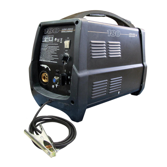
CAUTION 1. Working Environment. 1.1 The environment in which this welding equipment is installed must be free of grinding dust, corrosive chemicals, flammable gas or materials etc, and at no more than maximum of 80% humidity. 1.2 When using the machine outdoors protect the machine from direct sun light, rain water and snow etc; the temperature of working environment should be maintained within -10°C to +40°C. - Page 9 FRONT PANEL LAYOUT ON/OFF Power Switch Wire Speed Adjustment Knob Thermal Overload Light Voltage Selecion Knob SpoolGun Power Supply Connection Earth Lead Primary Power Supply Connection Standard Mig/Spool Gun Selector Switch Euro Mig Torch Connector (MIG/MAG) BACK PANEL LAYOUT 10. Gas Inlet 11.
- Page 10 INSTALLATION & OPERATION Please install the machine strictly according to the following steps. The protection class of this machine is IP21S, so avoid using it in rain. Connection of Input Cables Primary input cable is supplied with this welding equipment. Connect the primary input cable with power supply of required input voltage.
- Page 11 Installation set up for MIG with Gas for UNI-MIG MIG180 (1) Plug Primay power supply cable into 15amp power outlet. (2) Select Standard MIG using the Standard/Spool Gun selector switch. (3) Plug the welding torch into the Euro Mig torch connection socket on the front panel, and tighten it. When connecting the torch be sure to tighten the connection.
- Page 12 Continued set up for MIG with Gas for UNI-MIG MIG180 (9) Align the wire into the groove of the drive roller and close down the top roller making sure the wire is in the groove of the bottom drive roller, lock the pressure arm into place. (10) Apply a medium amount of pressure to the drive roller.
- Page 13 Wire Feed Roller Selection The importance of smooth consistent wire feeding during MIG welding cannot be emphasized enough. Simply put the smoother the wire feed then the better the welding will be. Feed rollers or drive rollers are used to feed the wire mechanically along the length of the welding gun. Feed rollers are designed to be used for certain types of welding wire and they have different types of grooves machined in them to accommodate the different types of wire.
- Page 14 Wire Installation and Set Up Guide Again the importance of smooth consistent wire feeding during MIG welding cannot be emphasized enough. The correct installation of the wire spool and the wire into the wire feed unit is critical to achieving an even and consistent wire feed.
- Page 15 Installation set up for MIG with Gasless wire for UNI-MIG MIG180 (1) Plug Primay power supply cable into 15amp power outlet. (2) Select Standard MIG using the Standard/Spool Gun selector switch. (3) Plug the welding torch into the Euro Mig torch connection socket on the front panel, and tighten it. When connecting the torch be sure to tighten the connection.
- Page 16 Continued set up for MIG with Gasless wire for UNI-MIG MIG180 (8) Carefully feed the wire over the drive roller into the outlet guide tube, feed through about 150mm into the torch receptacle. Check that the drive roller being used complies with the wire diameter, replace the roller if necessary.
- Page 17 Mig Torch Liner Installation (1) Lay the torch out straight on the ground and remove the front end parts (2) Remove the liner retaining nut. (3) Carefully pull the liner out of the torch cable assembly (4) Select the correct new liner and carefully unravel avoiding putting any kinks in the liner, if you kink the liner it will make it no good and will require replacement.
- Page 18 Torch & Wire Feed Set Up for Aluminium Wire (1) Lay the torch out straight on the ground and remove the front end parts (2) Remove the liner retaining nut. (3) Carefully pull the liner out of the torch cable assembly (4) Select a PA or liner, carefully and slowly feed the liner in short forward movements down the cable assembly all the way through and out the torch neck end.
- Page 19 Continued Torch & Wire Feed Set Up for Aluminium Wire (10) Remove circlip from guide tube. (11) Remove the inlet guide tube from the front end machine euro connector using long nose pliers. (12) Carefully feed the extended PA liner section into the inlet guide tube hole of the machine euro connector (13) Feed the extended PA liner all the way up and over the drive roller (14) Tighten the torch euro connection to the machine euro connector...
- Page 20 Installation set up of the Spool Gun for UNI-MIG MIG180 (1) Plug Primay power supply cable into 15amp power outlet. (2) Switch on the machine, (3) Select Spool Gun using the Standard/Spool Gun selector switch. (4) Connect the Spool Gun to the Euro Mig torch connection socket on the front panel, and tighten it. Connect the Spool Gun control cable to the receptacle and tighten it.
- Page 21 Continued set up of the Spool Gun for UNI-MIG MIG180 (10) Carefully feed the wire through the red guide tube into meet the drive roller. Push down the tension arm adjustment lever to release the drive roll pressure allowing the wire to be guided through the drive rollers into the gun neck.
- Page 22 MIG (Metal Inert Gas) Welding Definition of MIG Welding MIG (metal inert gas) welding also known as GMAW (gas metal arc welding) or MAG (metal active gas welding), is a semi-automatic or automatic arc welding process in which a continuous and consumable wire electrode and a shielding gas are fed through a weld- ing gun.
- Page 23 MIG (Metal Inert Gas) Welding Short Circuit Transfer - Short circuit transfer is the most common used method whereby the wire electrode is fed continuously down the welding torch through to and exiting the contact tip. The wire touches the work piece and causes a short circuit the wire heats up and begins to form a molten bead, the bead separates from the end of the wire and forms a droplet that is transferred into the weld pool.
- Page 24 Basic MIG Welding Good weld quality and weld profile depends on gun angle, direction of travel, electrode extension (stick out), travel speed, thickness of base metal, wire feed speed (amperage) and arc voltage. To follow are some basic guides to assist with your setup. Gun Position - Travel Direction, Work Angle Gun position or technique usually refers to how the wire is directed at the base metal, the angle and travel direction chosen.
- Page 25 Travel Angle - Travel angle is the right to left angle relative to the direction of welding. A travel angle of 5°- 15° is ideal and produces a good level of control over the weld pool. A travel angle greater that 20° will give an unstable arc condition with poor weld metal transfer, less penetration, high levels of spatter, poor gas shield and poor quality finished weld.
- Page 26 Travel Speed - Travel speed is the rate that the gun is moved along the weld joint and is usually measured in mm per minute. Travel speeds can vary depending on conditions and the welders skill and is limited to the welders ability to control the weld pool. Push technique allows faster travel speeds than Drag technique.
- Page 27 Wire types and sizes - Use the correct wire type for the base metal being welded. Use stainless steel wire for stainless steel, aluminium wires for aluminium and steel wires for steel. Use a smaller diameter wire for thin base metals. For thicker materials use a larger wire diameter and larger machine, check the recommended welding capability of you machine.
- Page 28 Suregrip Series SB15 MIG TORCH 180A AIR COOLED MIG WELDING TORCH Rating:180A CO² 150A mixed gas EN60974-7 @ 60% duty cycle. 0.6 to 1.0mm wires Wear parts next page Wear parts next page Torch Model Description Part Number 3 Mt 4 Mt 5 Mt SB Suregrip Ergo Torch Package SB15-3M...
- Page 29 Suregrip Series SB15 MIG TORCH Front end consumables SB15 Contact Tips Part Number Description PCT0008-06 Contact Tip Steel (0.6mm) QTY10 PCT0008-08 Contact Tip Steel (0.8mm) QTY10 PCT0008-09 Contact Tip Steel (0.9mm) QTY10 PCT0008-10 Contact Tip Steel (1.0mm) QTY10 PCTAL0008-09 Contact Tip Aluminium (0.9mm) QTY10 25.0 PCTAL0008-10 Contact Tip Aluminium (1.0mm) QTY10 SB15 Tip Holder Part Number Description PCTH15 Contact Tip Holder (Suit SB15) QTY2 42.0...
- Page 30 SPG135 AMP SPOOL GUN L135YE SPOOL GUN Duty Cycle 30% @ 135Amp Description Part Number XcelArc Spool Gun SPG135 x 6m SPG135 Spare Parts Part Number Description Part Number Description LGJ2003 Trigger LGX2018 LMH2001 Handle LGX2019U DriveRoll U Groove 0.8-0.9mm LMT2001 Spool Cover Total Assembly LZ3603...
- Page 31 SPG135 AMP SPOOL GUN Duty Cycle 30% @ 135Amp Front end consumables SPG135 Contact Tips Part Number Description PCT0008-06 Contact Tip Steel (0.6mm) PCT0008-08 Contact Tip Steel (0.8mm) PCT0008-09 Contact Tip Steel (0.9mm) PCT0008-10 Contact Tip Steel (1.0mm) PCTAL0008-09 Contact Tip Aluminium (0.9mm) 25.0 PCTAL0008-10 Contact Tip Aluminium (1.0mm) SPG135 Tip Holder Part Number Description PCTH15 Contact Tip Holder 42.0 SPG135 Gas Nozzle Part Number Description...
- Page 32 MIG WELDING TROUBLE SHOOTING The following chart addresses some of the common problems of MIG welding. In all cases of equipment malfunction, the manu- facturer’s recommendations should be strictly adhered to and followed. 1: Excessive Spatter Possible Reason Suggested Remedy Wire feed speed set too high Select lower wire feed speed Voltage too high...
- Page 33 MIG WIRE FEED TROUBLE SHOOTING The following chart addresses some of the common WIRE FEED problems during MIG welding. In all cases of equipment malfunction, the manufacturer’s recommendations should be strictly adhered to and followed. 1: No wire feed Possible Reason Suggested Remedy Wrong mode selected Check that the TIG/MMA/MIG selector switch set to MIG position...
- Page 34 ATTENTION! - CHECK FOR GAS LEAKS At initial set up and at regular intervals we recommend to check for gas leakage. Recommended procedure is as follows: 1. Connect the regulator and gas hose assembly and tighten all connectors and clamps. 2.
- Page 36 Welding Guns Of Australia PTY LTD 2012 Welding Guns Of Australia PTY LTD Pty Ltd ABN: 14 001 804 422 PO Box 3033, Lansvale NSW 2166, AUSTRALIA 112 Christina Rd, Villawood, NSW 2163 Phone: (02) 9780 4200 Fax: (02) 9780 4244 Email: sales@unimig.com.au / Web: www.unimig.com.au...
Need help?
Do you have a question about the KMM180 and is the answer not in the manual?
Questions and answers