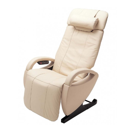
Summary of Contents for Sanyo HEC-FX1
- Page 1 FILE No. Relaxation Chair HEC-FX1 SERVICE MANUAL HEC-RX1 (U.S.A.) SM6510564-00 REFERENCE NO. - 1 -...
-
Page 2: Specifications
Specifications HEC-FX1/RX1 Power source AC Local voltage 50/60 Hz Power consumption 100 W (LOW voltage) / 110 W (HIGH voltage) Rating time 30 minutes Timer Approx. 15 minutes 780 mm (30 ") [width] x 1,030 mm (40 ") [depth] x 1,230 mm (48 ") [height]... - Page 3 Name/Function of Each Part HEC-FX1/RX1 Head rest Pillow Back rest Seat Control Arm rest Foot rest Cord Power plug Caster POWER switch - 3 -...
-
Page 4: Wiring Diagram (For Low Voltage)
Wiring Diagram (for LOW voltage) HEC-FX1/RX1 Reclining Motor (Foot Rest) Reclining Motor (Back Rest) Switch Switch Motor Motor Limit SW (Back Rest) CN10 CN11 Printed board (Main) Valve (No.5) Valve (No.1) Valve (No.6) Valve (No.2) Valve (No.7) Valve (No.3) Air Pump Valve (No.8) -
Page 5: Wiring Diagram (For High Voltage)
Wiring Diagram (for HIGH voltage) HEC-FX1/RX1 Printed board Reclining Motor (Foot Rest) Reclining Motor (Back Rest) (Transformer) Switch Switch Motor Motor CN301 Limit SW (Back Rest) CN10 CN11 Printed board (Main) Valve (No.5) Valve (No.1) Valve (No.6) Valve (No.2) Valve (No.7) Valve (No.3) - Page 6 Air-Bag Operation Confirmation Procedure HEC-FX1/RX1 1, Start-up of Examination Mode Turn ON the POWER switch at the rear of the main body while simultaneously pressing the RECLINING "DOWN" and LEG "DOWN" buttons on the control. (This operation should be started with the POWER switch turned OFF).
- Page 7 Motor Operation Confirmation Procedure HEC-FX1/RX1 1, Start-up of Examination Mode Turn ON the POWER switch at the rear of the main body while simultaneously pressing the RECLINING "DOWN" and LEG "DOWN" buttons on the control. (This operation should be started with the POWER switch turned OFF).
- Page 8 Problem Diagnosis Chart HEC-FX1/RX1 Troubled portion Check item Counteraction method Check the current fuse for fusion. Replace the current fuse. Check the power cord for disconnection. Replace the power cord. The POWER switch failure. Replace the POWER switch. The connection confirmation of Printed board (main) CN1.
-
Page 9: Replacement Procedure
Replacement Procedure HEC-FX1/RX1 (1) Replacement of Arm Rest Assembly and Cover (Arm Rest Lower) Right 5, Remove two arm rest set screws, disconnect 1, Remove two arm rest set screws on the back the connector between the arm rest (right) of main body. - Page 10 Replacement Procedure HEC-FX1/RX1 (2) Replacement of PCB (Main) (3) Replacement of Valve 1, Remove three cover (back cover) set screws 1, Take off the cover (back cover) and the arm and take off the cover (back cover). rest (right). Photo-1,2,3...
- Page 11 Replacement Procedure HEC-FX1/RX1 (4) Replacement of Air Pump and (6) Replacement of Reclining Motor PCB (Transformer) 1, Take off the cover (back cover) and the arm 1, Take off the cover (back cover) and the arm rest (left/right). Photo-1,2,3 rest (right).
- Page 12 Replacement Procedure HEC-FX1/RX1 (7) Replacement of Control 1, Take off the arm rest (right). Photo-1,2,3 5, Remove eleven cover (arm rest) right set 2, Remove two control set screws on the rear screws and take off the cover (arm rest) of a stay (control), disconnect a connector right.
- Page 13 (power supply box upper). Photo-17 Power supply box Fuse cover Power supply box set screws Photo-16 Case set screws Current Fuse Case (power supply box upper) Photo-17 SANYO Electric Co.,Ltd - 13 - Nov./2007 Printed in Japan Osaka, Japan...


Need help?
Do you have a question about the HEC-FX1 and is the answer not in the manual?
Questions and answers