Advertisement
Quick Links
A L L
P U R P O S E
V I N Y L
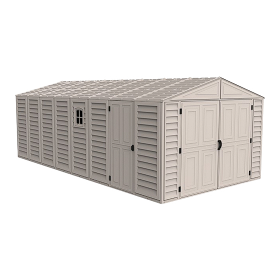
Vinyl Garage
Vinyl Garage
Garage
Garage
OWNER'S MANUAL /
Instructions for Assembly
Size 10'x 15'
Ver: 1.0
Your Total Solution To maintenance Free Garages.
• All Weather Durable PVC
• Won't Dent, Rust, Rot or Mildew
• Tall Walk In Shed
• Never Needs Painting
• 89" Wide Double Doors
• Easy Assembly
• High Wind Tested
• Snow Load Tested 20lbs/sq. foot
• Pad Lock Ready (Lock not included)
Available Kits
• Window Kits Available
TM
U S P
U S P
A Product of
US POLYMERS INC
G A R A G E S
Patent #416.091
Customer
Service Hotline
(800) 483-4674
www.uspolymersinc.com
Requires two people and takes about
4-5 hours for Installation.
Call us for any missing or damaged parts.
Do not return to the store.
Advertisement

Related Manuals for DuraMax Vinyl

Summary of Contents for DuraMax Vinyl
- Page 1 A Product of US POLYMERS INC A L L P U R P O S E V I N Y L G A R A G E S Vinyl Garage Vinyl Garage Garage Garage Patent #416.091 OWNER’S MANUAL / Instructions for Assembly Size 10’x 15’...
- Page 2 Duramax Garages Limited Ten Year Warranty U.S. Polymer Inc. will send a replacement part free of charge, in the event of material defects and or workmanship for a period of ten years from the date of purchase. This warranty is extended only to the original purchaser. A purchase receipt or other proof of date of original purchase will be required before warranty service is rendered.
- Page 3 Parts List Note: Check all parts prior to installation. CODE DESCRIPTION CODE DESCRIPTION LEFT DOOR COLUMN RIGHT DOOR COLUMN (CDLA) (CDLH) (CDRA) (CDRH) B1LH FRONT ‘U’ CHANNEL LEFT RS16L DOOR STOPPER LEFT B1RH FRONT ‘U’ CHANNEL RIGHT RS16R DOOR STOPPER RIGHT B1LA FRONT ‘U’...
- Page 4 Exploded View RS2A RS3LA RS1H RS4XA RS3LA RS4XA RS2A RS6H RS4XA RS1H RS4XA RS15R RS15L RS3LH RS2A RS3LA RS4XA RS1H RS5A RS7H RS16L RS15R RS3LA RS16R RS4XA RS3LA RS1H RS2A CB3XA CB3XA CDLH CDRH CB6H CB3XA EXTL B3LA CB1A B3RA CB4A B1LA B1RA...
- Page 5 Roof Structure Exploded View RS10A RS2A RS2A RS1H RS9H RS8H RS3LA RS4XA RS1H RS12A RS4XA RS2A RS4XA RS3LA RS15R RS4XA RS20H RS3LA RS19H RS4XA RS15L RS12A RS4XA RS4XA RS3LA RS15R RS4XA RS20H RS19H RS4XA RS3LA RS15L RS12A RS5A DSHH RS5A RS4XA RS5A RS2A...
- Page 6 A. Foundation Note: It is important that these instructions are followed step by step. All parts are clearly marked and care should Note be taken to use the correct one. Parts Needed: (2) Foundation ‘U’ Channel (F01H) (2) Foundation ‘U’ Channel (F02H) (4) Foundation ‘L’...
- Page 7 . Assemble the channel (F04A), (F05A) & (F07) together using (S1) screws. Make 6 sets. F05A F04A . Make a frame with the sub assemblies as shown below. Make sure while assembling, the Note channel position should be as shown. F01H F02H F05A...
- Page 8 . Fix the ‘L’ angle (F03) to the channel at all the four corners to make a perfect frame. See fig. . Fix the channel (F04A), (F05A) & (F07) sub assembly into the main frame as shown. See fig. Make sure while assembling, the Note channel position should be as shown.
- Page 9 . Place the channel (F03H) into the frame equaly spaced as shown. Use (F08) plate to connect the ‘U’ channel and the frame with (S1) screws. F03H F03H . Assemble the Base U-Channel on top of the foundation with (S1) screws as shown in fig. EXTL B3LA EXTL...
- Page 10 . Place the ramp (RG) to the front side of the foundation and keep the distance according to the wheel distance. Use dia. 2.5mm. drill bit to transfer the hole from (RG) and fix with (S1) screws. Gravel Filler Material and Flooring Recommendation OPTION - 1.
- Page 11 Secure the plywood to the foundation with screws. (Screws not included.) Concrete OPTION - 2. Cement Floor with out Plywood. After completing the assembly of the base U-channel fill the concrete up to the foundation top surface only. Ramp Concrete B.
- Page 12 . Slide the door column (CDRA) into the base U-channel (B1RH) on the right side of the door. Line up the pre drilled holes on column (CDRA) with base ‘U’ channel. Secure with two (S1) screws from inside. See fig. CDRA CDRA B1RH...
-
Page 13: Fsph ) Pushing The Column To The Side Panel
. Slide the corner column (CCA) into side panel (FSPH ) pushing the column to the side panel. FSPH B1RH FSPH Fig.1 Fig.2 FSPH Fig.3 2&3 . Fix the center band fitting (FCB) to the column (CCA) with (S2) screw. Leave it loose. -
Page 14: 6 . Fix The Center Band (Cb4H) To The Base 'U
. Fix the center band (CB1H) to the center band fitting (FCB) with (S1) screws. See fig.1. Fix the other end to the door column (CDRA). See fig.2. CDRA CB1H CDRA CB1H CB1H Fig.1 Fig.2 . Fix the center band (CB4H) to the base ‘U’ channel (B1RH) and door column (CDRA) with (S1) screws. - Page 15 . Working from inside continue connecting the 6 side panels (SP ) and columns to the base ‘U’ channel. Use (S1) screws to fix column to base. Window can be fixed any place Note except front panel. . Slide the corner column (CCA) into side panel (SP ) pushing the column to the side panel.
- Page 16 . Fix the center band fitting (FCB) to the column (CCA) with (S2) screw. Leave it loose. Back . Assemble the center bands (CB3XA) with middle joining support (MJ) with (S1) Screws. See fig.1. Assemble (CB3XA) & (CB3A) together with (S1) screws. See fig.2. CB3XA CB3A CB3XA...
- Page 17 . Stabilize the side panels with center bands (CB3XA) & (CB3A) assembly. See fig.1 to 6 and follow the steps. 1&5 3&6 CB3XA CB3XA CB3XA CB3XA Fig.1 Fig.2 CB3A CB3XA CB3A CB3XA Fig.4 Fig.3 CB3XA CB3XA CB3XA CB1H Fig.5 Fig.6 .
- Page 18 . Slide the corner column (CCA) into side panel (SP ) pushing the column to the side panel. Working from outside use (S1) screws to secure column to base (B3LA) & (EXTL). B3LA EXTL Fig.1 Fig.2 B3LA EXTL 2&3 EXTL Fig.3 .
- Page 19 . Assemble the center bands (CB3XA) with middle joining support (MJ) with (S1) screws. See fig. CB3XA CB3XA CB3XA CB3XA . Stabilize the side panels with center bands (CB3XA) assembly. See fig.1 to 6 and follow the steps. CB3XA CB3XA 1&5 Fig.2 Fig.1...
- Page 20 . Working from inside continue connecting the side panels (SP ) and columns to the base ‘U’ channel. Use (S1) screws to fix column to base. EXTL EXTL EXTL B1LA . Slide the door column (CDLH) into the base ‘U’ Channel & side panel. Line up the pre drilled holes on (CDLH) &...
- Page 21 . Assemble the center bands (CB3XA) & (CB6H) with middle joining support (MJ) with (S1) Screws. See fig. CB3XA CB3XA CB6H CB6H . Stabilize the side panels with center bands (CB3XA) & (CB6H) assembly. See fig.1 to 5 and follow the steps. CB3XA CB3XA CB3XA...
- Page 22 . Fix the (EPS) at the end of center band (CB6H). See fig.1. Fix the (CBC) to the center band joint position to avoide injury. See fig.2. CDLH CB3XA CB6H CB3XA CDLH CB6H CB6H Fig.1 Fig.2 . Slide the door column (CDRH) into the base ‘U’...
- Page 23 . Insert the side panel (SP ) into the groove of column (CDRH) & base ‘U’ channel (B1RA). CDRH B1RA . Slide the corner column (CCA) into side panel (SP ) pushing the column to the side panel. Working from outside use (S1) screws to secure column to base (B1RA) &...
- Page 24 . Fix the center band fitting (FCB) to the column (CCA) with (S2) screw. Leave it loose. . Fix the center band (CB1A) to the center band fitting (FCB) with (S1) screws. See fig.1. Fix the other end to the door column (CDRH). See fig.2. CDRH CDRH CB1A...
- Page 25 . Fix the center band (CB4A) to the base ‘U’ channel (B1RA) and door column (CDRH) with (S1) screws. See fig.1&2. Fix the (EPS) at the end of (CB1A) & (CB4A). See fig.3. CB4A CDRH CB1A 2&3 CDRH B1RA CB4A Fig.2 Fig.1 CB4A...
- Page 26 . Slide the door column (CDLA) into the base ‘U’ Channel & side panel. Line up the pre drilled holes on (CDLA) & base ‘U’ channel (B1LH) & fix with (S1) screws from inside. FSPH FSPH CDLA CDLA B1LH CDLA Fig.2 Fig.1 B1LH...
-
Page 27: S1) Screws. See Fig.1&2. Fix The (Eps) At The End Of (Cb1H) & (Cb4H). See Fig
. Fix the center band (CB4H) to the base ‘U’ channel (B1LH) and door column (CDLA) with (S1) screws. See fig.1&2. Fix the (EPS) at the end of (CB1H) & (CB4H). See fig.3. CB4H CDLA 2&3 CDLA B1LH CB4H Fig.1 Fig.2 CB4H CB1H... - Page 28 C. Roof Frame Parts Needed: (4) RS1 Roof Structure (RS1H) (1) Door Stopper Left (RS16L) (4) RS8 Roof Structure Support Long (RS8H) (1) Door Stopper Right (RS16R) (4) RS9 Roof Structure Support Short (RS9H) (1) Door Column Fitting Left (FDCL) (6) Middle Joining Support (MJ) (1) Door Column Fitting Left...
- Page 29 . Insert the corner column fittings (FCC) into the corner column (CCA). Fix with (S1) screws from outside of the shed. . Insert the door column fittings (FDCLC) & (FDCRH) into the front door column (CDLA) & (CDRA). See fig.1&2. Insert the door column fittings (FDCL) &...
- Page 30 Front roof structure assembly . Assemble front roof structures (RS1H) 2 nos. with middle joining support (MJ). Use (S1) screws. RS1H RS1H RS1H RS1H . Assemble roof structure support (RS8H) & (RS9H) to (RS1H) assembly with 4 (S1) screws as RS9H shown in fig.
- Page 31 . Assemble the roof structure (RS2A) to (RS8H) & (RS9H) with 8 (S1) screws. RS2A RS2A RS9H RS8H RS2A RS8H RS9H . Assemble door stopper (RS16L) & (RS16R) together with (S8) bolt & nut with washers. RS16L RS16R...
- Page 32 . Assemble (RS16R) & (RS16L) assembly to front roof assembly with (S1) screws. RS16L RS16R Back roof structure assembly . Assemble front roof structures (RS1H) 2 nos. with middle joining support (MJ). Use (S1) screws. RS1H RS1H RS1H RS1H...
- Page 33 . Assemble roof structure support (RS8H) & (RS9H) to (RS1H) assembly with 8 (S1) screws as RS9H shown in fig. Make sure these holes up RS8H RS1H RS8H RS9H RS1H . Assemble the roof structure (RS2A) to (RS8H) & (RS9H) with 8 (S1) screws. RS2A RS2A RS2A...
- Page 34 . Assemble roof structure (RS3LA) with middle joining support (MJ). Use (S1) screws to fix. RS3LA RS3LA RS3LA RS3LA RS3LA . Insert 90 degree joint (RJ) into the roof structure (RS3LA). Use (S1) screw to fix. Repeat on other end of (RS3LA). RS3LA RS3LA RS3LA...
- Page 35 . Assemble roof structure (RS3LA) & (RS3LH) with middle joining support (MJ). Use (S1) screws to fix. RS3LA RS3LA RS3LH RS3LA RS3LH . Insert 90 degree joint (RJ) into the roof structure (RS3LH). Use (S1) screw to fix. Repeat on other end of (RS3LA).
- Page 36 . Assemble the roof structure (RS5A) & (RS6H) with (S1) screws. Make 2 sets. Do not fix any screws on this two holes. Do not fix any screws on this two holes. RS6H RS6H RS6H RS6H RS5A . Assemble the roof structure (RS13A) into (RS5A) &...
- Page 37 . Assemble the roof structure (RS5A) & (RS7H) with (S1) screws. Make 2 sets. RS7H RS7H Do not fix any screws on this two holes. RS7H RS7H Do not fix any screws on this two holes. RS5A . Assemble the roof structure (RS13A) into (RS5A) &...
- Page 38 . Place the assembled front roof structure assembly to the door columns. Line up the pre drilled holes with door column and fix with (S1) screws. See fig.1&2. Make sure the (RS2A) structure position as shown in fig.3. RS16L RS16R RS16R RS16L CDLA...
- Page 39 . Insert the 90 degree joint (RJ) (assembled with (RS3) roof structure) into the roof structure (RS1H). See fig.1. Secure (RJ) to (RS1H) with (S1) screw. See fig.2. Secure (RJ) with (FCC) using (S2) screw. See RS3LA RS3LA fig.3 Fix (RS2A) to (RJ) through (RS3) assembly with (S1) screw.
- Page 40 . Fix the door stopper (DSHH) to the roof structure (RS3LH) with (S1) screws. RS3LH RS3LH DSHH CDLH DSHH CDRH CDRH . Place the assembled roof structure (RS5A) & (RS6H) into position on roof structure supports (RS8H) at the left side of the shed. Use (S1) screws to fix.
- Page 41 . Place the assembled roof structure (RS5A) & (RS6H) into position on roof structure supports (RS9H) at the left side of the shed. Use (S1) screws to fix. See fig.1&2. Repeat the same for assembling (RS5A) & (RS7H) assembly. RS6H RS7H RS5A RS5A...
- Page 42 . Attach the roof structure (RS4XA) 10 nos. to (RS3LH) & (RS3LA) assembly with (S1) screws. See fig.1. Attach the roof structure (RS4XA) to (RS5A), RS4XA (RS6A) assembly and (RS5A), (RS7A) assembly with (S7) screws. See fig.2&3. RS4XA RS4XA RS4XA RS4XA RS4XA RS4XA...
- Page 43 . Attach the roof structure support (RS12A) with (RS5A) to (RS5A) and (RS6H) to (RS7H) with (S1) screws. RS12A RS12A RS5A RS12A RS12A . Assemble the roof structure support (RS15L) & (RS15R) together with (S8) bolt & nut with RS15L RS15R...
- Page 44 . Fix the assembled roof structure support (RS15L) & (RS15R) to the column (CMH) & (CDLH) with (S1) & (S2) screws. See fig. RS15L RS15L RS15R RS15L RS15L RS15R CDLH Fig.1 CDLH Fig.2 . Attach the roof structure support (RS15L) & (RS15R) assembly to (RS19H) &...
- Page 45 D. Roof panels Parts Needed: (12) Roof Panels (RP ) Facia Panel Left (FPL) Facia Panel Right (FPR) Ridge Cover Small (RRS) (128) Roof Plug with Washer (PPG) (128) Roof Pin (PIN) (24) Sagging Support (RS14A) . Place facia panel (FPR) to front roof structure right side.
- Page 46 . Place facia panel (FPR) to back roof structure right side. Repeat the same step 1. Back . Place facia panel (FPL) to back roof structure left side. Repeat the same step 1. Back...
- Page 47 Use a screw driver to align the Note . Start attaching the roof panels from (FPL) corner holes. side by sliding the roof panel (RP ) to roof structure. Locate the hole positions of the roof panel and roof Insert roof plugs into roof panels structure.
- Page 48 . Continue to attaching the roof panels from back right. After fixing each roof panel attach each ridge cover (RRS). See fig. and follow the steps. Fig. 2 Fig. 1 Fig. 3 Fig. 4 Fig. 5 Fig. 6...
- Page 49 Fig. 7 Fig. 8 Fig. 9 Fig. 10 Fig. 11 Fig. 12...
- Page 50 . Insert the sagging support (RS14A) from inside the shed by sliding in between roof structure (RS5) and roof panel until it reaches (RS3) roof structure for each panel. See fig.1. . Insert the sagging support (RS14A) from inside the shed by sliding in between roof structure (RS5) and roof panel until it touches the other roof structure (RS5).
- Page 51 Note: To prevent water leakage it is important that these instructions are followed. After completing the assembly apply silicone around the perimeter of the base U-channel. Seal the corners, joints and base of door column Base U-channel After completing the panel assembly, apply silicone around the roof plugs.
- Page 52 Optional Ventilation Kit ACCESSORIES CODE DESCRIPTION VENTILATION COVER VENTILATION COVER PIN VENTILATION COVER (VC) VENTILATION COVER PIN (VCP) TOOLS YOU WILL NEED Power Drill Dia 5/32” (4.2mm) drill bit Dia 1/2” (12.5mm) drill bit Optional ventilation kits can be installed on any of the wall panels.
- Page 53 High wind area installation instructions Note: To ensure that your shed withstands high winds, you will need the following reinforcement. Parts needed: CODE DESCRIPTION DIA. 4.2 x 16mm. (5/32” x 5/8”) SHEET METAL SCREW (not included with shed) M6 x 40mm. (1/4” x 1 1/2”) (not included with shed) Anchor bolt with nut .
- Page 54 Important Warranty Information The Duramax shed has been tested and passed wind loads of up to 115 mph in a controlled laboratory environment. Natural high wind areas create wind at unpredictable speeds that are very difficult to capture accurately by location. As such we cannot guarantee the performance...
Need help?
Do you have a question about the Vinyl and is the answer not in the manual?
Questions and answers