Table of Contents
Advertisement
Quick Links
Intel® Desktop Board
DG33BU
Technical Product Specification
®
The Intel
Desktop Board DG33BU may contain design defects or errors known as errata that may cause the product to deviate from published specifications. Current
characterized errata are documented in the Intel Desktop Board DG33BU Specification Update.
May 2007
Order Number: D88104-001US
Advertisement
Table of Contents

Related Manuals for Intel DG33BU


Summary of Contents for Intel DG33BU
- Page 1 ® The Intel Desktop Board DG33BU may contain design defects or errors known as errata that may cause the product to deviate from published specifications. Current characterized errata are documented in the Intel Desktop Board DG33BU Specification Update. May 2007...
-
Page 2: Revision History
Current characterized errata are available on request. Contact your local Intel sales office or your distributor to obtain the latest specifications before placing your product order. -
Page 3: Intended Audience
Intended Audience The TPS is intended to provide detailed, technical information about the Desktop Board DG33BU and its components to the vendors, system integrators, and other engineers and technicians who need this level of information. It is specifically not intended for general audiences. -
Page 4: Other Common Notation
Other Common Notation Used after a signal name to identify an active-low signal (such as USBP0#) Gigabyte (1,073,741,824 bytes) GB/sec Gigabytes per second Gbit Gigabit (1, 073,741,824 bits) Kilobyte (1024 bytes) Kbit Kilobit (1024 bits) kbits/sec 1000 bits per second Megabyte (1,048,576 bytes) MB/sec Megabytes per second... -
Page 5: Table Of Contents
1.4 Processor ... 15 1.5 System Memory ... 16 1.5.1 Memory Configurations ... 17 ® 1.6 Intel G33 Express Chipset ... 19 1.6.1 Intel G33 Graphics Subsystem ... 19 ® 1.6.2 Intel Viiv™ Processor Technology ... 21 1.6.3 USB ... 21 1.6.4 Serial ATA Interfaces ... - Page 6 2 Technical Reference 2.1 Memory Map... 37 2.1.1 Addressable Memory... 37 2.2 Connectors and Headers... 40 2.2.1 Back Panel Connectors ... 41 2.2.2 Component-side Connectors and Headers ... 42 2.3 Jumper Block ... 50 2.4 Mechanical Considerations ... 51 2.4.1 Form Factor...
- Page 7 5.1.1 Safety Standards... 73 5.1.2 European Union Declaration of Conformity Statement ... 74 5.1.3 Product Ecology Statements... 75 5.1.4 EMC Regulations ... 79 5.1.5 Product Certification Markings (Board Level)... 80 5.2 Battery Disposal Information... 81 Figures Major Board Components... 12 Block Diagram ...
- Page 8 25. Recommended Power Supply Current Values ... 52 26. Fan Header Current Capability... 53 27. Thermal Considerations for Components ... 55 28. Desktop Board DG33BU Environmental Specifications ... 56 29. BIOS Setup Program Menu Bar... 58 30. BIOS Setup Program Function Keys... 58 31.
- Page 9 1.2 Legacy Considerations... 15 1.3 Online Support... 15 1.4 Processor ... 15 1.5 System Memory ... 16 ® 1.6 Intel G33 Express Chipset ... 19 1.7 Parallel IDE Controller ... 22 1.8 Real-Time Clock Subsystem ... 23 1.9 Legacy I/O Controller ... 23 1.10 Audio Subsystem...
-
Page 10: Overview
Intel Desktop Board DG33BU Technical Product Specification Overview 1.1.1 Feature Summary Table 1 summarizes the major features of the Desktop Board DG33BU. Table 1. Feature Summary Form Factor microATX (9.60 inches by 9.60 inches [243.84 millimeters by 243.84 millimeters]) Processor Support for the following: •... -
Page 11: Product Description
• Thermal sense to detect out of range thermal values • Three fan headers • Three fan sense inputs used to monitor fan activity For information about Available configurations for the Desktop Board DG33BU ® Management Refer to Section 1.2, page 15... -
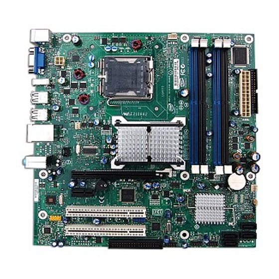
Page 12: Board Layout
1.1.2 Board Layout Figure 1 shows the location of the major components. Table 2 lists the components identified in Figure 1. Figure 1. Major Board Components... -
Page 13: Board Components Shown In Figure 1
Main Power connector (2 X 12) Diskette drive connector Chassis intrusion header Battery Front chassis fan header Intel 82801IH I/O Controller Hub (ICH9DH) BIOS Setup configuration jumper block Auxiliary front panel power LED header Front panel header Serial ATA connectors [4]... -
Page 14: Block Diagram
Intel Desktop Board DG33BU Technical Product Specification 1.1.3 Block Diagram Figure 2 is a block diagram of the major functional areas. Figure 2. Block Diagram... -
Page 15: Legacy Considerations
The board is designed to support the following processors: • Intel Core 2 Quad processor in an LGA775 socket with a 1066 MHz system bus • Intel Core 2 Duo processor in an LGA775 socket with a 1066 or 800 MHz system bus •... -
Page 16: System Memory
Intel Desktop Board DG33BU Technical Product Specification INTEGRATOR’S NOTE Use only ATX12V-compliant power supplies. For information about Power supply connectors System Memory The board has four DIMM sockets and supports the following memory features: • 1.8 V (only) DDR2 SDRAM DIMMs with gold-plated contacts •... -
Page 17: Memory Configurations
1.5.1 Memory Configurations The Intel 82G33 GMCH supports the following types of memory organization: • Dual channel (Interleaved) mode. This mode offers the highest throughput for real world applications. Dual channel mode is enabled when the installed memory capacities of both DIMM channels are equal. Technology and device width can vary from one channel to the other but the installed memory capacity for each channel must be equal. -
Page 18: Memory Channel Configuration And Dimm Configuration
Intel Desktop Board DG33BU Technical Product Specification Figure 3 illustrates the memory channel and DIMM configuration. NOTE The DIMM 0 sockets of both channels are blue. The DIMM 1 sockets of both channels are black. Figure 3. Memory Channel Configuration and DIMM Configuration INTEGRATOR’S NOTE... -
Page 19: Intel G33 Express Chipset
Either the Intel Graphics Media Accelerator 3100 (Intel GMA 3100) graphics controller (contained within the 82G33 GMCH) is used, or a PCI Express x16 add-in card can be used. When a PCI Express x16 add-in card is installed, the Intel GMA 3100 graphics controller is disabled. -
Page 20: Configuration Modes
225 MHz pixel clock to the PCI Express x16 connector. When an ADD2/MEC card is detected, the Intel GMA 3100 graphics controller is enabled and the PCI Express x16 connector is configured for SDVO mode. SDVO mode enables the SDVO ports to be accessed by the ADD2/MEC card. -
Page 21: Intel Viiv™ Processor Technology
Intel Viiv™ Processor Technology This Intel desktop board supports Intel Viiv processor technology. To be eligible for the Intel Viiv processor technology brand, a system must meet certain hardware and software requirements. To get the list of requirements for Intel Viiv processor... -
Page 22: Parallel Ide Controller
NOTE Many Serial ATA drives use new low-voltage power connectors and require adapters or power supplies equipped with low-voltage power connectors. For more information, see: For information about The location of the Serial ATA connectors Parallel IDE Controller The Parallel ATA IDE controller has one bus-mastering Parallel ATA IDE interface. The Parallel ATA IDE interface supports the following modes: •... -
Page 23: Real-Time Clock Subsystem
Real-Time Clock Subsystem A coin-cell battery (CR2032) powers the real-time clock and CMOS memory. When the computer is not plugged into a wall socket, the battery has an estimated life of three years. When the computer is plugged in, the standby current from the power supply extends the life of the battery. -
Page 24: Ps/2 Keyboard And Mouse Interface
A signal-to-noise (S/N) ratio of 95 dB • Independent 5.1 audio playback from back panel connectors and stereo playback from the Intel High Definition Audio front panel header. NOTE Systems built with AC 97 front panel will not be able to obtain the Microsoft Windows Vista* logo after June 2007. -
Page 25: Audio Subsystem Software
1.10.1 Audio Subsystem Software Audio software and drivers are available from Intel’s World Wide Web site. For information about Obtaining audio software and drivers 1.10.2 Audio Connectors and Headers The board contains audio connectors on the back panel and audio headers on the component side of the board. -
Page 26: 1.11 Lan Subsystem
For information about LAN software and drivers ® 1.11.1 Intel 82566DC Gigabit Ethernet Controller The Intel 82566DC Gigabit Ethernet Controller supports the following features: • PCI Express link • 10/100/1000 IEEE 802.3 compliant • Compliant to IEEE 802.3x flow control support •... -
Page 27: Lan Subsystem Software
1.11.2 LAN Subsystem Software LAN software and drivers are available from Intel’s World Wide Web site. For information about Obtaining LAN software and drivers 1.11.3 RJ-45 LAN Connector with Integrated LEDs Two LEDs are built into the RJ-45 LAN connector (shown in Figure 5 below). -
Page 28: 1.12 Hardware Management Subsystem
Intel Desktop Board DG33BU Technical Product Specification 1.12 Hardware Management Subsystem The hardware management features enable the board to be compatible with the Wired for Management (WfM) specification. The board has several hardware management features, including the following: • Fan monitoring and control •... -
Page 29: Thermal Monitoring
1.12.4 Thermal Monitoring Figure 6 shows the locations of the thermal sensors and fan headers. Item Figure 6. Thermal Sensors and Fan Headers NOTE The minimum thermal reporting threshold for the GMCH is 66°C. The GMCH thermal sensor will display 66°C until the temperature rises above this point. Description Thermal diode, located on processor die Thermal diode, located on the GMCH die... -
Page 30: 1.13 Power Management
Intel Desktop Board DG33BU Technical Product Specification 1.13 Power Management Power management is implemented at several levels, including: • Software support through Advanced Configuration and Power Interface (ACPI) • Hardware support: ⎯ Power connector ⎯ Fan headers ⎯ LAN wake capabilities ⎯... -
Page 31: Power States And Targeted System Power
1.13.1.1 System States and Power States Under ACPI, the operating system directs all system and device power state transitions. The operating system puts devices in and out of low-power states based on user preferences and knowledge of how devices are being used by applications. Devices that are not being used can be turned off. -
Page 32: Wake-Up Devices And Events
1.13.1.2 ENERGY STAR* In 2007, the US Department of Energy and the US Environmental Protection Agency revised the ENERGY STAR* requirements. Intel has worked directly with these two governmental agencies to define the new requirements. Currently Intel Desktop Boards meet the new requirements. -
Page 33: Hardware Support
1.13.2 Hardware Support CAUTION Ensure that the power supply provides adequate +5 V standby current if LAN wake capabilities and Instantly Available PC technology features are used. Failure to do so can damage the power supply. The total amount of standby current required depends on the wake devices supported and manufacturing options. -
Page 34: Fan Headers
Intel Desktop Board DG33BU Technical Product Specification 1.13.2.2 Fan Headers The function/operation of the fan headers is as follows: • The fans are on when the board is in the S0 state. • The fans are off when the board is off or in the S3, S4, or S5 state. -
Page 35: Instantly Available Pc Technology
1.13.2.4 Instantly Available PC Technology CAUTION For Instantly Available PC technology, the +5 V standby line from the power supply must be capable of providing adequate +5 V standby current. Failure to provide adequate standby current when implementing Instantly Available PC technology can damage the power supply. -
Page 36: Location Of The Standby Power Indicator Led
Intel Desktop Board DG33BU Technical Product Specification 1.13.2.9 +5 V Standby Power Indicator LED The +5 V standby power indicator LED shows that power is still present even when the computer appears to be off. Figure 7 shows the location of the standby power indicator LED. -
Page 37: Technical Reference
GMCH base address registers, internal graphics ranges, PCI Express ports (up to 512 MB) • Memory-mapped I/O that is dynamically allocated for PCI Conventional and PCI Express add-in cards • Intel Management Engine support (6 MB) • Base graphics memory support (1 MB or 8 MB) -
Page 38: Detailed System Memory Address Map
Intel Desktop Board DG33BU Technical Product Specification The amount of installed memory that can be used will vary based on add-in cards and BIOS settings. Figure 8 shows a schematic of the system memory map. All installed system memory can be used when there is no overlap of system addresses. -
Page 39: System Memory Map
Table 9 lists the system memory map. Table 9. System Memory Map Address Range Address Range (decimal) (hex) 1024 K - 8388608 K 100000 - 1FFFFFFFF 960 K - 1024 K F0000 - FFFFF 896 K - 960 K E0000 - EFFFF 800 K - 896 K C8000 - DFFFF 640 K - 800 K... -
Page 40: Connectors And Headers
Intel Desktop Board DG33BU Technical Product Specification Connectors and Headers CAUTION Only the following connectors and headers have overcurrent protection: Back panel and front panel USB, PS/2, and VGA. The other internal connectors/headers are not overcurrent protected and should connect only to devices inside the computer’s chassis, such as fans and internal peripherals. -
Page 41: Back Panel Connectors
2.2.1 Back Panel Connectors Figure 9 shows the locations of the back panel connectors. Item Description PS/2 mouse port PS/2 keyboard port VGA port IEEE 1394a port USB ports [2] USB ports [2] USB ports [2] Line in Mic in Line out Figure 9. -
Page 42: Component-Side Connectors And Headers
Intel Desktop Board DG33BU Technical Product Specification 2.2.2 Component-side Connectors and Headers Figure 10 shows the locations of the component-side connectors and headers. Figure 10. Component-side Connectors and Headers... -
Page 43: Component-Side Connectors And Headers Shown In Figure 10
Table 10 lists the component-side connectors and headers identified in Figure 10. Table 10. Component-side Connectors and Headers Shown in Figure 10 Item/callout from Figure 10 Description PCI Conventional bus add-in card connector 1 Front panel audio header PCI Conventional bus add-in card connector 2 PCI Express x1 connector PCI Express x16 connector Processor core power connector (2 X 2) -
Page 44: Serial Ata Connectors
2.2.2.1 Signal Tables for the Connectors and Headers Table 11. Serial ATA Connectors Signal Name Ground Ground Ground Table 12. Chassis Intrusion Header Signal Name Intruder Ground Table 13. Serial Port Header Signal Name TXD# Ground Table 14. Front and Rear Chassis Fan Headers Signal Name Control +12 V... -
Page 45: Front Panel Audio Header
Table 16. Front Panel Audio Header Signal Name [Port 1] Left channel [Port 1] Right channel [Port 2] Right channel SENSE_SEND (Jack detection) [Port 2] Left channel 2.2.2.2 Add-in Card Connectors The board has the following add-in card connectors: • One PCI Express x16 connector supporting simultaneous transfer speeds up to 4 GBytes/sec of peak bandwidth per direction and up to 8 GBytes/sec concurrent bandwidth. -
Page 46: Processor Core Power Connector
Main power – a 2 x 12 connector. This connector is compatible with 2 x 10 connectors previously used on Intel Desktop boards. The board supports the use of ATX12V power supplies with either 2 x 10 or 2 x 12 main power cables. When... -
Page 47: Connection Diagram For Front Panel Header
2.2.2.5 Front Panel Header This section describes the functions of the front panel header. Table 20 lists the signal names of the front panel header. Figure 11 is a connection diagram for the front panel header. Table 20. Front Panel Header Signal Hard Drive Activity LED HD_PWR... -
Page 48: States For A One-Color Power Led
Intel Desktop Board DG33BU Technical Product Specification 2.2.2.5.2 Reset Switch Header Pins 5 and 7 can be connected to a momentary single pole, single throw (SPST) type switch that is normally open. When the switch is closed, the board resets and runs the POST. -
Page 49: Connection Diagram For Front Panel Usb Headers
2.2.2.7 Front Panel USB Headers Figure 12 is a connection diagram for the front panel USB headers. INTEGRATOR’S NOTES • The +5 V DC power on the front panel USB headers is fused. • Use only a front panel USB connector that conforms to the USB 2.0 specification for high-speed USB devices. -
Page 50: Jumper Block
Intel Desktop Board DG33BU Technical Product Specification Jumper Block CAUTION Do not move the jumper with the power on. Always turn off the power and unplug the power cord from the computer before changing a jumper setting. Otherwise, the board could be damaged. -
Page 51: Mechanical Considerations
Mechanical Considerations 2.4.1 Form Factor The board is designed to fit into an ATX- or microATX-form-factor chassis. Figure 14 illustrates the mechanical form factor of the board. Dimensions are given in inches [millimeters]. The outer dimensions are 9.60 inches by 9.60 inches [243.84 millimeters by 243.84 millimeters]. -
Page 52: Electrical Considerations
Intel Desktop Board DG33BU Technical Product Specification Electrical Considerations 2.5.1 Power Supply Considerations CAUTION The +5 V standby line from the power supply must be capable of providing adequate +5 V standby current. Failure to do so can damage the power supply. The total amount of standby current required depends on the wake devices supported and manufacturing options. -
Page 53: Fan Header Current Capability
Failure to ensure appropriate airflow may result in reduced performance of both the processor and/or voltage regulator or, in some instances, damage to the board. For a list of chassis that have been tested with Intel desktop boards please refer to the following website: http://developer.intel.com/design/motherbd/cooling.htm... -
Page 54: Localized High Temperature Zones
Intel Desktop Board DG33BU Technical Product Specification CAUTION Ensure that proper airflow is maintained in the processor voltage regulator circuit. Failure to do so may result in damage to the voltage regulator circuit. The processor voltage regulator area (shown in Figure 15) can reach a temperature of up to 95 an open chassis. -
Page 55: Reliability
The MTBF data is calculated from predicted data at 55 ºC. The Desktop Board DG33BU MTBF is 136,977 hours. Maximum Case Temperature For processor case temperature, see processor datasheets and... -
Page 56: Environmental
Intel Desktop Board DG33BU Technical Product Specification Environmental Table 28 lists the environmental specifications for the board. Table 28. Desktop Board DG33BU Environmental Specifications Parameter Specification Temperature Non-Operating -40 °C to +70 °C Operating 0 °C to +55 °C Shock... -
Page 57: Overview Of Bios Features
3.10 BIOS Security Features ... 65 Introduction The board uses an Intel BIOS that is stored in the Serial Peripheral Interface Flash Memory (SPI Flash) and can be updated using a disk-based program. The SPI Flash contains the BIOS Setup program, POST, the PCI auto-configuration utility, and Plug and Play support. -
Page 58: Bios Flash Memory Organization
Intel Desktop Board DG33BU Technical Product Specification Table 29 lists the BIOS Setup program menu features. Table 29. BIOS Setup Program Menu Bar Maintenance Main Clears Displays passwords and processor displays and memory processor configuration information Table 30 lists the function keys available for menu screens. -
Page 59: Pci Ide Support
3.3.2 PCI IDE Support If you select Auto in the BIOS Setup program, the BIOS automatically sets up the PCI IDE connector with independent I/O channel support. The IDE interface supports hard drives up to ATA-66/100/133 and recognizes any ATAPI compliant devices, including CD-ROM drives, tape drives, and Ultra DMA drives. -
Page 60: Legacy Usb Support
Legacy USB support from the BIOS is no longer used. 7. Additional USB legacy feature options can be access by using Intel Integrator Toolkit. To install an operating system that supports USB, verify that Legacy USB support in the BIOS Setup program is set to Enabled and follow the operating system’s... -
Page 61: Bios Updates
BIOS update utilities 3.6.1 Language Support The BIOS Setup program and help messages are supported in US English. Additional languages are available in the Integrator’s Toolkit utility. Check the Intel website for details. Overview of BIOS Features Refer to http://support.intel.com/support/motherboards/desktop/s... -
Page 62: Custom Splash Screen
The Intel available from Intel can be used to create a custom splash screen. NOTE If you add a custom splash screen, it will share space with the Intel branded logo. For information about Intel Integrator Toolkit ®... -
Page 63: Boot Options
Boot Options In the BIOS Setup program, the user can choose to boot from a diskette drive, hard drive, USB drive, USB flash drive, CD-ROM, or the network. The default setting is for the diskette drive to be the first boot device, the hard drive second, and the ATAPI CD-ROM third. -
Page 64: Adjusting Boot Speed
It is possible to optimize the boot process to the point where the system boots so quickly that the Intel logo screen (or a custom logo splash screen) will not be seen. Monitors and hard disk drives with minimum initialization times can also contribute to a boot time that might be so fast that necessary logo screens and POST messages cannot be seen. -
Page 65: 3.10 Bios Security Features
3.10 BIOS Security Features The BIOS includes security features that restrict access to the BIOS Setup program and who can boot the computer. A supervisor password and a user password can be set for the BIOS Setup program and for booting the computer, with the following restrictions: •... - Page 66 Intel Desktop Board DG33BU Technical Product Specification...
-
Page 67: Error Messages And Beep Codes
Error Messages and Beep Codes What This Chapter Contains 4.1 Speaker ... 67 4.2 BIOS Beep Codes ... 67 4.3 BIOS Error Messages ... 67 4.4 Port 80h POST Codes ... 68 Speaker The board-mounted speaker provides audible error code (beep code) information during POST. -
Page 68: Port 80H Post Codes
Intel Desktop Board DG33BU Technical Product Specification Port 80h POST Codes During the POST, the BIOS generates diagnostic progress codes (POST codes) to I/O port 80h. If the POST fails, execution stops and the last POST code generated is left at port 80h. -
Page 69: Port 80H Post Codes
Table 37. Port 80h POST Codes POST Code Description of POST Operation Power-on initialization of the host processor (Boot Strap Processor) Host processor Cache initialization (including APs) Starting Application processor initialization SMM initialization Initializing a chipset component Reading SPD from memory DIMMs Detecting presence of memory DIMMs Programming timing parameters in the memory controller and the DIMMs Configuring memory... - Page 70 Intel Desktop Board DG33BU Technical Product Specification Table 37. Port 80h POST Codes (continued) POST Code Description of POST Operation Resetting keyboard Disabling keyboard Detecting presence of keyboard Enabling the keyboard Clearing keyboard input buffer Instructing keyboard controller to run Self Test (PS/2 only)
- Page 71 Table 37. Port 80h POST Codes (continued) POST Code Description of POST Operation Waiting for user input Checking password Entering BIOS setup Calling Legacy Option ROMs Entering Sleep state Exiting Sleep state EFI boot service ExitBootServices ( ) has been called EFI runtime service SetVirtualAddressMap ( ) has been called EFI runtime service ResetSystem ( ) has been called Crisis Recovery has initiated per User request...
-
Page 72: Typical Port 80H Post Sequence
Table 38. Typical Port 80h POST Sequence POST Code Description Initializing a chipset component Reading SPD from memory DIMMs Detecting presence of memory DIMMs Configuring memory Testing memory Loading recovery capsule Entered DXE phase Starting application processor initialization SMM initialization Enumerating PCI busses Allocating resourced to PCI bus Detecting the presence of the keyboard... -
Page 73: Regulatory Compliance And Battery Disposal Information
Electromagnetic Compatibility (EMC) standards • Product certification markings 5.1.1 Safety Standards Desktop Board DG33BU complies with the safety standards stated in Table 39 when correctly installed in a compatible host system. Table 39. Safety Standards Standard UL 60950-1, First Edition... -
Page 74: European Union Declaration Of Conformity Statement
European Union Declaration of Conformity Statement We, Intel Corporation, declare under our sole responsibility that the product Intel Desktop Board DG33BU is in conformity with all applicable essential requirements necessary for CE marking, following the provisions of the European Council Directive 2004/108/EC (EMC Directive) and 2006/95/EC (Low Voltage Directive). -
Page 75: Product Ecology Statements
请参考 http://www.intel.com/intel/other/ehs/product_ecology 了解此计划的详情,包括涉及产品之范围、回收地点、运送指导、条款和条件等。 Deutsch Als Teil von Intels Engagement für den Umweltschutz hat das Unternehmen das Intel Produkt-Recyclingprogramm implementiert, das Einzelhandelskunden von Intel Markenprodukten ermöglicht, gebrauchte Produkte an ausgewählte Standorte für ordnungsgemäßes Recycling zurückzugeben. Details zu diesem Programm, einschließlich der darin eingeschlossenen Produkte, verfügbaren Standorte, Versandanweisungen, Bedingungen usw., finden Sie auf der... - Page 76 Français Dans le cadre de son engagement pour la protection de l'environnement, Intel a mis en œuvre le programme Intel Product Recycling Program (Programme de recyclage des produits Intel) pour permettre aux consommateurs de produits Intel de recycler les produits usés en les retournant à...
-
Page 77: Lead Free Desktop Board
Russian В качестве части своих обязательств к окружающей среде, в Intel создана программа утилизации продукции Intel (Product Recycling Program) для предоставления конечным пользователям марок продукции Intel возможности возврата используемой продукции в специализированные пункты для должной утилизации. Пожалуйста, обратитесь на веб-сайт... -
Page 78: Lead-Free Board Markings
Intel Desktop Board DG33BU Technical Product Specification Table 40 shows the various forms of the “Lead-Free 2 appears on the board and accompanying collateral. Table 40. Lead-Free Board Markings Description Lead-Free 2 Level Interconnect: This symbol is used to identify electrical and... -
Page 79: Emc Regulations
5.1.4 EMC Regulations Desktop Board DG33BU complies with the EMC regulations stated in Table 41 when correctly installed in a compatible host system. Table 41. EMC Regulations Regulation FCC 47 CFR Part 15, Subpart B ICES-003 Issue 4 (Class B) -
Page 80: Product Certification Markings (Board Level)
EMC requirements. You may use this equipment in residential environments and other non-residential environments. 5.1.5 Product Certification Markings (Board Level) Desktop Board DG33BU has the product certification markings shown in Table 42: Table 42. Product Certification Markings Description UL joint US/Canada Recognized Component mark. Includes adjacent UL file number for Intel desktop boards: E210882. -
Page 81: Battery Disposal Information
Regulatory Compliance and Battery Disposal Information Battery Disposal Information CAUTION Risk of explosion if the battery is replaced with an incorrect type. Batteries should be recycled where possible. Disposal of used batteries must be in accordance with local environmental regulations. PRECAUTION Risque d'explosion si la pile usagée est remplacée par une pile de type incorrect. - Page 82 Intel Desktop Board DG33BU Technical Product Specification PRECAUCIÓN Existe peligro de explosión si la pila no se cambia de forma adecuada. Utilice solamente pilas iguales o del mismo tipo que las recomendadas por el fabricante del equipo. Para deshacerse de las pilas usadas, siga igualmente las instrucciones del fabricante.
- Page 83 Regulatory Compliance and Battery Disposal Information AWAS Risiko letupan wujud jika bateri digantikan dengan jenis yang tidak betul. Bateri sepatutnya dikitar semula jika boleh. Pelupusan bateri terpakai mestilah mematuhi peraturan alam sekitar tempatan. OSTRZEŻENIE Istnieje niebezpieczeństwo wybuchu w przypadku zastosowania niewłaściwego typu baterii.
- Page 84 Intel Desktop Board DG33BU Technical Product Specification...
Need help?
Do you have a question about the DG33BU and is the answer not in the manual?
Questions and answers