Intel DH55HC Product Manual
Desktop board
Hide thumbs
Also See for DH55HC:
- Technical product specification (86 pages) ,
- Specification update (7 pages) ,
- Product manual (82 pages)
Table of Contents
Advertisement
Advertisement
Table of Contents

Related Manuals for Intel DH55HC


Summary of Contents for Intel DH55HC
- Page 1 Intel® Desktop Board DH55HC Product Guide Order Number: E78886-001...
-
Page 2: Canadian Department Of Communications Compliance Statement
Intel may make changes to specifications and product descriptions at any time, without notice. Intel Desktop Board DH55HC may contain design defects or errors known as errata which may cause the product to deviate from published specifications. Current characterized errata are available on request. -
Page 3: Use Only For Intended Applications
The suitability of this product for other PC or embedded non-PC applications or other environments, such as medical, industrial, alarm systems, test equipment, etc. may not be supported without further evaluation by Intel. Document Organization The chapters in this Product Guide are arranged as follows:... - Page 4 Terminology The table below gives descriptions of some common terms used in the product guide. Term Description Gigabyte (1,073,741,824 bytes) Gigahertz (one billion hertz) Kilobyte (1024 bytes) Megabyte (1,048,576 bytes) Megabit (1,048,576 bits) Megahertz (one million hertz)
-
Page 5: Table Of Contents
Contents 1 Desktop Board Features Supported Operating Systems...11 Desktop Board Components...12 Processor...14 ® Intel H55 Express Chipset ...14 Main Memory...15 Graphics Subsystem ...15 Integrated Graphics ...15 Analog Display (VGA)...15 High-Definition Multimedia Interface* (HDMI*)...16 Digital Visual Interface (DVI-D) ...16 PCI Express* x16 Graphics ...16 Audio Subsystem ...17... - Page 6 Setting the BIOS Configuration Jumper ...55 Clearing Passwords ...56 Replacing the Battery ...57 3 Updating the BIOS Updating the BIOS with the Intel Updating the BIOS with the ISO Image BIOS Update File or the Iflash Memory Update Utility...64 Obtaining the BIOS Update File ...64 Updating the BIOS with the ISO Image BIOS Update File ...65...
- Page 7 24. Back Panel Audio Connectors ...52 25. Location of the Chassis Fan Headers...53 26. Connecting Power Supply Cables ...54 27. Location of the BIOS Configuration Jumper Block ...55 28. Removing the Battery ...62 29. Intel Desktop Board DH55HC China RoHS Material Self Declaration Table ...77...
- Page 8 11. Alternate Front Panel Power LED Header Signal Names ...49 12. Front Panel Header Signal Names ...50 13. USB 2.0 Header Signal Names...50 14. Front Panel USB Header (with Intel Z-U130 USB Solid-State Drive (or Compatible Device) Support) Signal Names...51 15. Serial Port Header ...51 16.
-
Page 9: Desktop Board Features
• Support for up to 16 GB of system memory with four DIMMs using • Support for non-ECC memory Graphics • Integrated graphics support for processors with Intel Graphics • Discrete graphics support for PCI Express* 2.0 x16 add-in graphics Audio... - Page 10 • Support for Platform Environmental Control Interface (PECI) ― Six ports are implemented with stacked back panel connectors ― Six ports are implemented with three dual-port internal headers; one header supports an Intel Z-U130 USB Solid-State Drive (or compatible device) eSATA adapters ®...
-
Page 11: Supported Operating Systems
Supported Operating Systems The Desktop Board supports the following operating systems: • Microsoft Windows* 7 Ultimate 64-bit edition • Microsoft Windows 7 Ultimate 32-bit edition • Microsoft Windows 7 Home Basic 64-bit edition • Microsoft Windows 7 Home Premium 64-bit edition •... -
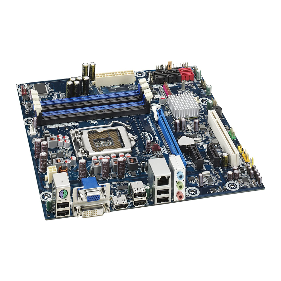
Page 12: Desktop Board Components
Desktop Board Components Figure 1 shows the approximate location of the major components on Intel Desktop Board DH55HC. Figure 1. Intel Desktop Board DH55HC Components... - Page 13 Alternate front panel power LED header Front panel header Standby power indicator LED Front panel USB 2.0 headers (2) Front panel USB header with support for an Intel Z-U130 USB Solid-State Drive (or compatible device) Parallel port header Speaker Serial port header...
-
Page 14: Processor
Desktop Board may result in damage to the board, or the system may not function properly. Intel Desktop Board DH55HC supports the Intel Core i7, and Intel Core i5, Intel Core i3, and Intel Pentium processors in an LGA1156 socket. Processors are not included with the Desktop Board and must be purchased separately. -
Page 15: Main Memory
4 GB because of the memory used by add-in graphics cards and other system resources. NOTE When using a processor without Intel Graphics Technology, memory must be installed in either or both of the DIMM 0 (blue) memory sockets for the system to boot. Graphics Subsystem The board supports either integrated graphics (Intel Graphics Technology) or PCI Express 2.0 x16 graphics. -
Page 16: High-Definition Multimedia Interface* (Hdmi*)
VGA or HDMI connectors. PCI Express* x16 Graphics The Intel Core i7, Intel Core i5, Intel Core i3, and Intel Pentium processors in an LGA1156 socket support discrete add-in graphics cards via the PCI Express 2.0 x16 add-in card connector. The board supports the following PCI Express speeds: •... -
Page 17: Audio Subsystem
Audio Subsystem The board supports Intel High Definition Audio through a Realtek ALC888S audio codec as well as through the HDMI interface. The Realtek ALC888S-based audio subsystem provides the following features: • Advanced jack sense for the back panel audio connectors that enables the audio codec to recognize the device that is connected to an audio port. -
Page 18: Usb 2.0 Support
Six ports via stacked back panel connectors • Six front panel ports via three dual-port internal headers; one header supports an Intel Z-U130 USB Solid-State Drive (or compatible device) USB 2.0 support requires both an operating system and drivers that fully support USB 2.0 transfer rates. -
Page 19: Expandability
Expandability Intel Desktop Board DH55HC provides the following expansion capability: • One PCI Express 2.0 x16 port • Two PCI Express 2.0 x1 ports • Three PCI bus interfaces Legacy I/O The board’s Legacy I/O Controller provides the following legacy features: •... -
Page 20: Security Passwords
For instructions on resetting the password, go to Clearing Passwords on page 56. Hardware Management The hardware management features of Intel Desktop Board DH55HC enable the board to be compatible with the Wired for Management (WfM) specification. The board has several hardware management features including the following: •... -
Page 21: Chassis Intrusion
Chassis Intrusion The board supports a chassis security feature that detects if the chassis cover has been removed. The security feature uses a mechanical switch on the chassis that can be connected to the chassis intrusion header on the Desktop Board. See Figure 1 for the location of the chassis intrusion header. -
Page 22: Fan Headers
Fan Headers The function/operation of the fans is as follows: • The fans are on when the board is in the ACPI S0 or S1 state. • The fans are off when the computer is in the ACPI S3, S4, or S5 state. •... -
Page 23: +5 V Standby Power Indicator Led
For example, when this green LED is lit, standby power is still present at the memory module sockets and the PCI bus connectors. Figure 3. Location of the Standby Power Indicator For more information on standby current requirements for the Desktop Board, refer to the Technical Product Specification at http://support.intel.com/support/motherboards/desktop/... -
Page 24: Wake From Usb
ENERGY STAR requirements. Intel has worked directly with these two governmental agencies in the definition of the new requirements. Intel Desktop Board DH55HC meets the following program requirements in an adequate system configuration, including appropriate selection of an efficient power supply: •... -
Page 25: Speaker
Speaker A speaker is mounted on the Desktop Board. The speaker provides audible error code (beep code) information during the Power-On Self-Test (POST). Refer to Appendix A for a description of the board’s beep codes. Real-Time Clock Subsystem A coin-cell battery (CR2032) powers the real-time clock and CMOS memory. When the computer is not plugged into a wall socket, the battery has an estimated life of three years. - Page 26 Intel Desktop Board DH55HC Product Guide...
-
Page 27: Installing And Replacing Desktop Board Components
• Install and remove a PCI Express x16 card • Connect Serial ATA cables • Install an Intel Z-U130 USB Solid-State Drive (or Compatible Device) • Connect to the internal headers and connectors • Connect to the audio system •... -
Page 28: Installation Precautions
Installation Precautions When you install and test the Intel Desktop Board, observe all warnings and cautions in the installation instructions. To avoid injury, be careful of: • Sharp pins on connectors • Sharp pins on printed circuit assemblies • Rough edges and sharp corners on the chassis •... -
Page 29: Installing The I/O Shield
Installing and Replacing Desktop Board Components Installing the I/O Shield The Desktop Board comes with an I/O shield. When installed in the chassis, the shield blocks radio frequency transmissions, protects internal components from dust and foreign objects, and promotes correct airflow within the chassis. Install the I/O shield before installing the Desktop Board in the chassis. -
Page 30: Installing And Removing The Desktop Board
Refer to your chassis manual for instructions on installing and removing the Desktop Board. Figure 5 shows the location of the mounting screw holes for Intel Desktop Board DH55HC. Figure 5. Intel Desktop Board DH55HC Mounting Screw Hole Locations... -
Page 31: Installing And Removing A Processor
Installing and Removing a Processor Instructions on how to install the processor on the Desktop Board are given below. Installing a Processor CAUTION Before installing or removing a processor, make sure the AC power has been removed by unplugging the power cord from the computer; the standby power LED should not be lit (see Figure 3 on page 23). -
Page 32: Lift The Load Plate
Intel Desktop Board DH55HC Product Guide 3. Rotate the socket lever to lift the load plate away from the socket (Figure 7, A). Make sure that the load plate is in the fully open position (Figure 7, B) while being careful not to damage adjacent components. -
Page 33: Remove The Socket Cover
4. Remove the protective socket cover from the socket by placing your thumb against the front edge of the cover and resting your index finger on the rear grip (Figure 8, A). Lift the front edge of the socket to disengage the cover from the socket and lift the cover up and away from the socket (Figure 8, B). -
Page 34: Remove The Processor From The Protective Cover
5. Remove the processor from its protective cover. Hold the processor only at the edges, being careful not to touch the bottom of the processor (see Figure 9). NOTE Do not discard the processor cover. Always replace the processor cover if you remove the processor from the socket. -
Page 35: Lower The Load Plate
7. Lower the load plate over the processor while leaving the socket lever in the open position (Figure 11). Figure 11. Lower the Load Plate 8. Lower the socket lever (Figure 12, B) while making sure that the front edge of the load plate slides under the shoulder screw cap as the lever is lowered (Figure 12, A). -
Page 36: Installing A Processor Fan Heat Sink
Installing a Processor Fan Heat Sink Intel Desktop Board DH55HC has mounting holes for a processor fan heat sink. For instructions on how to attach the processor fan heat sink to the Desktop Board, refer to the boxed processor manual or boxed thermal solution manual. -
Page 37: Installing And Removing System Memory
Installing and Removing System Memory Desktop board DH55HC has four 240-pin DDR3 DIMM sockets arranged as DIMM 0 and DIMM 1 in both Channel A and Channel B. NOTE A DIMM must be present in at least one of the DIMM 0 sockets when you are using only one or two DIMMs with a processor that does not support Intel Graphics Technology. -
Page 38: Three Dimms
Figure 15. Example Dual Channel Memory Configuration with Four DIMMs Three DIMMs If you want to use three DIMMs in a dual-channel configuration, install a matched pair of DIMMs equal in speed and size in the DIMM 0 (blue) socket of channel A and the DIMM 0 (blue) socket of channel B. -
Page 39: Installing Dimms
Installing and Replacing Desktop Board Components Installing DIMMs To make sure you have the correct DIMM, place it on the illustration of the DDR3 DIMM in Figure 17. All the notches should match with the DDR3 DIMM. Figure 17. Use DDR3 DIMMs... -
Page 40: Installing A Dimm
To install a DIMM, follow these steps: 1. Observe the precautions in "Before You Begin" on page 27. 2. Turn off all peripheral devices connected to the computer. Turn off the computer and disconnect the AC power cord. 3. Remove the computer’s cover and locate the DIMM sockets (see Figure 18). 4. -
Page 41: Removing Dimms
Removing DIMMs To remove a DIMM, follow these steps: 1. Observe the precautions in "Before You Begin" on page 27. 2. Turn off all peripheral devices connected to the computer. Turn off the computer. 3. Remove the AC power cord from the computer. 4. -
Page 42: Removing A Pci Express X16 Graphics Card
4. Connect a monitor to the graphics card according to the manufacturer’s instructions. Figure 19. Installing a PCI Express x16 Graphics Card Removing a PCI Express x16 Graphics Card Follow these instructions to remove a PCI Express x16 graphics card from a connector: 1. -
Page 43: Removing A Pci Express X16 Graphics Card
Installing and Replacing Desktop Board Components Figure 20. Removing a PCI Express x16 Graphics Card... -
Page 44: Connecting Serial Ata (Sata) Cables
Connecting Serial ATA (SATA) Cables SATA cables support the Serial ATA protocol. Each cable can be used to connect one internal SATA drive to the Desktop Board. For correct cable function: 1. Observe the precautions in “Before You Begin” on page 27. 2. -
Page 45: Installing An Intel ® Z-U130 Usb Solid-State Drive (Or Compatible Device)
Installing an Intel Drive (or Compatible Device) An Intel Z-U130 USB Solid-State Drive (or compatible device) can be installed on the Desktop Board by using the onboard USB 2.0 header indicated in Figure 1, Y. This header provides support for the solid state drive. -
Page 46: Connecting To The Internal Headers
Connecting to the Internal Headers Before connecting cables to any of the internal headers, observe the precautions in “Before You Begin” on page 27. Figure 23 shows the location of the internal headers and connectors on Intel Desktop Board DH55HC. Figure 23. Internal Headers... -
Page 47: Front Panel Audio Header
Front Panel Audio Header The front panel audio header shown in Figure 23, A supports both Intel High Definition (HD) Audio and AC ’97 Audio. Table 4 shows the pin assignments and signal names for HD Audio and Table 5 shows the pin assignments and signal names for AC ’97 Audio. -
Page 48: S/Pdif Header
S/PDIF Header Figure 23, C shows the location of the S/PDIF output header. Table 7 shows the pin assignments and signal names for the S/PDIF output header. Table 7. S/PDIF Header Signal Names Description Ground S/PDIF Out Key (no pin) +5 VDC Parallel Port Header Figure 23, D shows the location of the parallel port header. -
Page 49: Chassis Intrusion Header
Intruder# Ground ® Intel RPAT Header Figure 23, F shows the location of the Intel RPAT header. Table 10 shows the pin assignments and signal names for the Intel RPAT header. Table 10. Intel RPAT Header Signal Names Description RPAT#... -
Page 50: Front Panel Header
Front Panel Header Figure 23, H shows the location of the front panel header. Table 12 shows the pin assignments and signal names for the front panel header. Table 12. Front Panel Header Signal Names Description Hard Drive Activity LED Hard disk LED pull-up to +5 V Out Hard disk active LED Reset Switch... -
Page 51: Serial Header
Figure 23, J shows the location of the front panel USB 2.0 header (with Intel Z-U130 USB Solid-State Drive (or Compatible Device) Support) and Table 14 shows its pin assignments and signal names. Table 14. Front Panel USB Header (with Intel Z-U130 USB Solid-State Drive... -
Page 52: Connecting To The Audio System
Connecting to the Audio System After installing the Realtek audio driver from the Intel the multi-channel audio feature can be enabled. Figure 24 shows the back panel audio connectors. The default connector assignments are shown in the table. Figure 24. Back Panel Audio Connectors... -
Page 53: Connecting Chassis Fan And Power Supply Cables
Connecting Chassis Fan and Power Supply Cables Connecting Chassis Fan Cables Connect chassis fan cables to the chassis fan headers on the Desktop Board. Figure 25 shows the location of the chassis fan headers. Figure 25. Location of the Chassis Fan Headers... -
Page 54: Connecting Power Supply Cables
Connecting Power Supply Cables CAUTION Failure to use an appropriate power supply and/or not connecting the 12 V power connector (Figure 26, A) to the Desktop Board may result in damage to the board or the system may not function properly. Figure 26 shows the location of the power connectors. -
Page 55: Setting The Bios Configuration Jumper
Installing and Replacing Desktop Board Components Setting the BIOS Configuration Jumper NOTE Always turn off the power and unplug the power cord from the computer before moving the jumper. Moving the jumper with the power on may result in unreliable computer operation. -
Page 56: Clearing Passwords
The three-pin BIOS jumper block enables board configuration to be done in the BIOS Setup program. Table 16 shows the jumper settings for the BIOS Setup program modes. Table 16. Jumper Settings for the BIOS Setup Program Modes Jumper Setting Mode Normal (default) (1-2) Configure (2-3) -
Page 57: Replacing The Battery
8. Use the arrow keys to select Clear Passwords. Press <Enter> and Setup displays a pop-up screen requesting that you confirm clearing the password. Select Yes and press <Enter>. Setup displays the maintenance menu again. 9. Press <F10> to save the current values and exit Setup. 10. - Page 58 Intel Desktop Board DH55HC Product Guide OBS! Det kan oppstå eksplosjonsfare hvis batteriet skiftes ut med feil type. Brukte batterier bør kastes i henhold til gjeldende miljølovgivning. VIKTIGT! Risk för explosion om batteriet ersätts med felaktig batterityp. Batterier ska kasseras enligt de lokala miljövårdsbestämmelserna.
- Page 59 Installing and Replacing Desktop Board Components AŚCIAROŽZNAŚĆ Існуе рызыка выбуху, калі заменены акумулятар неправільнага тыпу. Акумулятары павінны, па магчымасці, перепрацоўвацца. Пазбаўляцца ад старых акумулятараў патрэбна згодна з мясцовым заканадаўствам па экалогіі. UPOZORNÌNÍ V případě výměny baterie za nesprávný druh může dojít k výbuchu. Je-li to možné, baterie by měly být recyklovány.
- Page 60 Intel Desktop Board DH55HC Product Guide ВНИМАНИЕ При использовании батареи несоответствующего типа существует риск ее взрыва. Батареи должны быть утилизированы по возможности. Утилизация батарей должна проводится по правилам, соответствующим местным требованиям. UPOZORNENIE Ak batériu vymeníte za nesprávny typ, hrozí nebezpečenstvo jej výbuchu. Batérie by sa mali podľa možnosti vždy recyklovať.
- Page 61 Installing and Replacing Desktop Board Components...
-
Page 62: Removing The Battery
To replace the battery, follow these steps: 1. Observe the precautions in "Before You Begin" (see page 27). 2. Turn off all peripheral devices connected to the computer. Disconnect the computer’s power cord from the AC power source (wall outlet or power adapter). 3. -
Page 63: Updating The Bios
Power-On Self-Test (POST) memory test begins and before the operating system boot begins. This chapter tells you how to update the BIOS by either using the Intel Express BIOS Update utility or the Iflash Memory Update utility, and how to recover the BIOS if an update fails. -
Page 64: Updating The Bios With The Iso Image Bios Update File Or The Iflash Memory Update Utility
Intel Flash Memory Update Utility You can obtain either of these files through your computer supplier or by navigating to the Intel Desktop Board DH55HC page on the Intel World Wide Web site at: http://support.intel.com/support/motherboards/desktop Navigate to the DH55HC page, click “Latest BIOS and driver updates,” select “BIOS Update [TCIBX10H.86A],”... -
Page 65: Updating The Bios With The Iso Image Bios Update File
Enter key. The system will boot from the hard drive if no key is pressed within 15 seconds. 5. At the "Welcome to the Intel Desktop Board BIOS Upgrade CD-ROM" page, press any key to confirm the BIOS upgrade operation. -
Page 66: Updating The Bios With The Iflash Memory Update Utility
CD-ROM, bootable USB flash drive, or other bootable USB media. The utility available on the Intel World Wide Web site provides a simple method for creating a bootable CD-ROM that will automatically update your BIOS. The Iflash BIOS update files can also be extracted locally to your hard drive and copied to a bootable USB flash drive or other bootable USB media. -
Page 67: A Error Messages And Indicators
A Error Messages and Indicators Intel Desktop Board DH55HC reports POST errors in two ways: • By sounding a beep code and blinking the front panel power LED • By displaying an error message on the monitor BIOS Error Codes Whenever a recoverable error occurs during POST, the BIOS causes the board’s... -
Page 68: Bios Error Messages
Table 18. Front-panel Power LED Blink Codes Type Pattern F2 Setup/F10 Boot None Menu Prompt BIOS update in Off when the update begins, then on for progress 0.5 seconds, then off for 0.5 seconds. The pattern repeats until the BIOS update is complete. -
Page 69: B Regulatory Compliance
• Electromagnetic Compatibility (EMC) regulations • Product certifications Safety Standards Intel Desktop Board DH55HC complies with the safety standards stated in Table 20 when correctly installed in a compatible host system. Table 20. Safety Standards Regulation CSA/UL 60950-1, First Edition... -
Page 70: European Union Declaration Of Conformity Statement
European Union Declaration of Conformity Statement We, Intel Corporation, declare under our sole responsibility that the product Intel Desktop Board DH55HC is in conformity with all applicable essential requirements necessary for CE marking, following the provisions of the European Council Directives 2004/108/EC (EMC Directive) and 2006/95/EC (Low Voltage Directive). -
Page 71: Product Ecology Statements
The following information is provided to address worldwide product ecology concerns and regulations. Recycling Considerations As part of its commitment to environmental responsibility, Intel has implemented the Intel Product Recycling Program to allow retail consumers of Intel’s branded products ®... - Page 72 Français Dans le cadre de son engagement pour la protection de l'environnement, Intel a mis en œuvre le programme Intel Product Recycling Program (Programme de recyclage des produits Intel) pour permettre aux consommateurs de produits Intel de recycler les produits usés en les retournant à...
- Page 73 Portuguese Como parte deste compromisso com o respeito ao ambiente, a Intel implementou o Programa de Reciclagem de Produtos para que os consumidores finais possam enviar produtos Intel usados para locais selecionados, onde esses produtos são reciclados de maneira adequada.
-
Page 74: Lead-Free 2Li/Pb-Free 2Li Board
FLI is acceptable because of the RoHS "flip chip" or "die bump" interconnect exemption. Intel Desktop Board DH55HC is a lead-free second level interconnect product. Table 21 shows the lead-free second level interconnect marks as they appear on the board and accompanying collateral. These marks are based on JEDEC standard J-STD-609, “Marking and Labeling of Components, PCBs and PCBAs to Identify Lead,... -
Page 75: Restriction Of Hazardous Substances (Rohs)
Polybrominated biphenyls (PBB) • Polybrominated diphenyl ether (PBDE) The maximum concentrations allowed are 0.1% or 1000 ppm (except for cadmium, which is limited to 0.01% or 100 ppm) by weight of homogeneous material. Intel Desktop Board DH55HC complies with these restrictions. Mark... -
Page 76: China Rohs
The EFUP for Intel Desktop Boards has been determined to be 10 years. The EFUP for Intel Desktop Board DH55HC is shown in Table 22. Table 22. China RoHS Environmentally Friendly Use Period Mark... -
Page 77: Intel Desktop Board Dh55Hc China Rohs Material Self Declaration Table
Regulatory Compliance The China MII stipulates that a material Self Declaration Table (SDT) must be included in a product’s user documentation. The SDT for Intel Desktop Board DH55HC is shown in Figure 29. Figure 29. Intel Desktop Board DH55HC China RoHS Material... -
Page 78: Emc Regulations
EMC Regulations Intel Desktop Board DH55HC complies with the EMC regulations stated in Table 23 when correctly installed in a compatible host system. Table 23. EMC Regulations Regulation (Class B) FCC 47 CFR Part 15, Subpart B ICES-003 Issue 4... -
Page 79: Ensure Electromagnetic Compatibility (Emc) Compliance
Korean Class B statement translation: This is household equipment that is certified to comply with EMC requirements. You may use this equipment in residential environments and other non-residential environments. Ensure Electromagnetic Compatibility (EMC) Compliance Before computer integration, make sure that the power supply and other modules or peripherals, as applicable, have passed Class B EMC testing and are marked accordingly. -
Page 80: Product Certifications
Product Certifications Board-Level Certification Markings Intel Desktop Board DH55HC has the product certification markings shown in Table 24. Table 24. Product Certification Markings Description UL joint US/Canada Recognized Component mark. Includes adjacent UL file number for Intel Desktop Boards: E210882. -
Page 81: Chassis And Component Certifications
Regulatory Compliance Chassis and Component Certifications Ensure that the chassis and certain components; such as the power supply, peripheral drives, wiring, and cables; are components certified for the country or market where used. Agency certification marks on the product are proof of certification. Typical product certifications include: In Europe The CE marking signifies compliance with all applicable European requirements. - Page 82 Intel Desktop Board DH55HC Product Guide...
Need help?
Do you have a question about the DH55HC and is the answer not in the manual?
Questions and answers