Intel D425KT Product Manual
Desktop board
Hide thumbs
Also See for D425KT:
- Technical product specification (92 pages) ,
- Product manual (60 pages) ,
- Specification update (6 pages)
Table of Contents
Advertisement
Advertisement
Table of Contents

Related Manuals for Intel D425KT


Summary of Contents for Intel D425KT
- Page 1 Intel® Desktop Board D425KT Product Guide Order Number: E95572-001...
-
Page 2: Revision History
Intel Corporation by going to the World Wide Web site at: http://www.intel.com/ or by calling 1-800-548-4725. Intel, the Intel logo, and Intel Atom are trademarks of Intel Corporation in the U. S. and other countries. * Other names and brands may be claimed as the property of others. -
Page 3: Intended Audience
The suitability of this product for other PC or embedded non-PC applications or other environments, such as medical, industrial, alarm systems, test equipment, etc. may not be supported without further evaluation by Intel. Document Organization The chapters in this Product Guide are arranged as follows:... - Page 4 Terminology The table below gives descriptions to some common terms used in the product guide. Term Description Gigabyte (1,073,741,824 bytes) Gigahertz (one billion hertz) Kilobyte (1024 bytes) Megabyte (1,048,576 bytes) Mbit Megabit (1,048,576 bits) Megahertz (one million hertz)
-
Page 5: Table Of Contents
Clearing Passwords ...36 Replacing the Battery ...37 3 Updating the BIOS Updating the BIOS with the Intel Updating the BIOS with the Iflash Memory Update Utility ...44 Obtaining the BIOS Update File ...44 Using the Iflash Memory Update Utility ...44 Recovering the BIOS ...45... - Page 6 A Board Status and Error Messages BIOS Beep Codes ...47 BIOS Front-panel Power LED Blink Codes ...48 POST Error Messages...48 B Regulatory Compliance Safety Standards ...49 Battery Caution ...49 European Union Declaration of Conformity Statement...50 Product Ecology Statements ...51 Recycling Considerations ...51 China RoHS ...54 EMC Regulations ...55 FCC Declaration of Conformity ...55...
- Page 7 11. Connecting Power Supply Cables ...34 12. BIOS Configuration Jumper Block...35 13. Removing the Battery ...41 14. Intel Desktop Board D425KT China RoHS Material Self Declaration Table ...54 Tables 1. Feature Summary... 9 2. Intel Desktop Board D425KT Components ...12 3.
- Page 8 Intel Desktop Board D425KT Product Guide viii...
-
Page 9: Desktop Board Features
1 Desktop Board Features This chapter briefly describes the main features of Intel Table 1 summarizes the features of the Desktop Board. Table 1. Feature Summary Form Factor Mini-ITX ([170 millimeters [6.7 inches] x 170 millimeters [6.7 inches]) Processor Passively-cooled, soldered-down single-core Intel with integrated graphics and memory controllers. - Page 10 • Support for PCI Local Bus Specification, Revision 2.3 PC Technology • Support for Advanced Configuration and Power Interface (ACPI) • Wake on USB, PCI, PS/2, LAN, serial, and front panel For more information on Intel Desktop Board D425KT consult the following online resources: To find information about…...
-
Page 11: Desktop Board Components
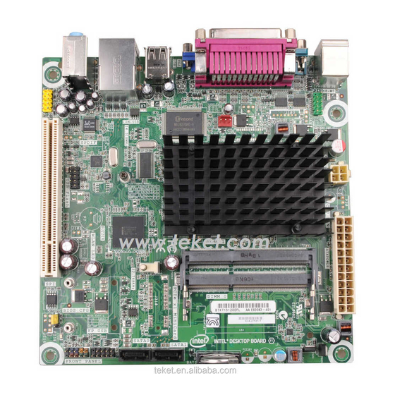
Desktop Board Features Desktop Board Components Figure 1 shows the location of the major components on Intel Desktop Board D425KT. Figure 1. Intel Desktop Board D425KT Components... -
Page 12: Intel Desktop Board D425Kt Components
Table 2. Intel Desktop Board D425KT Components Label Description Back panel connectors Serial header (COM1) Chassis fan header 12 V processor core voltage connector (2 x 2 pin) Processor Main power connector (2 x 12 pin) SO-DIMM 0 slot SO-DIMM 1 slot... -
Page 13: Processor
Processor Intel Desktop Board D425KT includes a passively-cooled, single-core Intel Atom processor with integrated graphics and memory controller. The processor is soldered to the Desktop Board and is not customer upgradeable. NOTE The board is designed to be passively cooled in a properly ventilated chassis. Chassis venting locations are recommended above the processor heatsink area for maximum heat dissipation effectiveness. -
Page 14: Integrated Graphics Subsystem
Supports analog displays up to 2048 x 1536 at 75 Hz refresh (QXGA) ® Intel NM10 Express Chipset The Intel NM10 Express Chipset is a centralized controller for the board’s I/O paths. For more information about the Intel NM10 Express Chipset, go to http://www.intel.com/products/chipsets/index.htm?iid=prod+prod_chipset. Operating System Support The following Microsoft* operating systems are fully supported by the Desktop Board: •... -
Page 15: Legacy Input/Output (I/O) Controller
The front/back panel audio connectors are configurable through the audio device drivers. Table 3 lists the supported functions of the front panel and back panel jacks. Table 3. Audio Jack Support Line Audio Jack Front panel – Green Front panel – Pink Back panel –... -
Page 16: Lan Subsystem
PCI bus power management ⎯ Supports ACPI technology ⎯ Supports LAN wake capabilities LAN drivers are available from Intel’s World Wide Web site at http://downloadcenter.intel.com/. Two LEDs are built into the RJ-45 LAN connector located on the back panel (see Figure 3). -
Page 17: Usb 2.0 Support
USB 2.0 Support The Desktop Board supports up to eight USB 2.0 ports (four ports routed to the back panel and four ports routed to two front panel USB 2.0 headers). The USB 2.0 ports are compatible with USB 1.1 devices. USB 1.1 devices will function normally at USB 1.1 speeds. -
Page 18: Security Passwords
Security Passwords The BIOS includes security features that restrict whether the BIOS Setup program can be accessed and who can boot the computer. A supervisor password and a user password can be set for the BIOS Setup and for booting the computer, with the following restrictions: •... -
Page 19: Standby Power Indicator
Figure 4. Location of the Standby Power Indicator For more information on standby current requirements for the Desktop Board, refer to the Technical Product Specification on the Intel Desktop D425KT web page at http://www.intel.com/products/motherboard/D425KT/index.htm. -
Page 20: Instantly Available Pc Technology
Instantly Available PC Technology Instantly Available PC technology enables the board to enter the ACPI S3 (Suspend-to- RAM) sleep-state. While in the ACPI S3 sleep-state, the computer will appear to be off (the hard drive(s) and fan will power off, the front panel power LED will blink). When signaled by a wake-up device or event, the system quickly returns to its last known state. -
Page 21: Battery
Battery A coin-cell battery on the Desktop Board keeps the values in CMOS RAM and the clock current when the computer is turned off. Go to page 37 for instructions on how to replace the battery. Real-Time Clock The Desktop Board includes a time-of-day clock and a 100-year calendar. The coin- cell battery keeps the clock current when the computer is turned off. - Page 22 Intel Desktop Board D425KT Product Guide...
-
Page 23: Installing And Replacing Desktop Board Components
2 Installing and Replacing Desktop Board Components This chapter tells you how to: • Install the I/O shield • Install and remove the Desktop Board • Install and remove system memory • Connect SATA drives • Connect to internal headers •... - Page 24 All responsibility for determining the adequacy of any thermal or system design remains solely with the reader. Intel makes no warranties or representations that merely following the instructions presented in this document will result in a system with adequate thermal performance.
-
Page 25: Installation Precautions
Installation Precautions When you install and test the Intel Desktop Board, observe all warnings and cautions in the installation instructions. To avoid injury, be careful of: • Sharp pins on connectors or headers • Sharp pins on printed circuit assemblies •... -
Page 26: Installing The I/O Shield
Installing the I/O Shield The Desktop Board comes with an I/O shield. When installed in the chassis, the shield blocks radio frequency transmissions, protects internal components from dust and foreign objects, and promotes correct airflow within the chassis. Install the I/O shield before installing the Desktop Board in the chassis. Place the shield inside the chassis as shown in Figure 5. -
Page 27: Installing And Removing The Desktop Board
Refer to your chassis manual for instructions on installing and removing the Desktop Board. Figure 6 shows the location of the mounting screw holes for Intel Desktop Board D425KT. Figure 6. Intel Desktop Board D425KT Mounting Screw Holes... -
Page 28: Installing And Removing Memory
Installing and Removing Memory NOTE To be fully compliant with all applicable Intel SDRAM memory specifications, the boards require DIMMs that support the Serial Presence Detect (SPD) data structure. The Desktop Board has two 204-pin DDR3 SO-DIMM sockets that support up to 4 GB of system memory. -
Page 29: Connecting Sata Drives
Installing and Replacing Desktop Board Components Connecting SATA Drives The board has two SATA connectors each supporting one SATA drive. The included SATA cables support the Serial ATA protocol. For correct cable and drive function: 1. Observe the precautions in "Before You Begin" on page 23. 2. -
Page 30: Connecting To The Internal Headers
Connecting to the Internal Headers Before connecting cables to the internal headers, observe the precautions in "Before You Begin" on page 23. Figure 9 shows the location of the board’s internal headers. Figure 9. Internal Headers... -
Page 31: Connecting To The Front Panel Audio Header
Figure 9, A shows the location of the front panel audio header. The front panel audio header can be used for both Intel HD Audio and AC ‘97 Audio. Table 5 shows the pin assignments for the Intel HD Audio and Table 6 shows the pin assignments for AC ‘97 Audio. -
Page 32: Front Panel Usb Headers
Connecting to the Front Panel Header Before connecting to the front panel header, observe the precautions in "Before You Begin" on page 23. See Figure 9, C on page 30 for the location of the front panel header. Table 8 shows the pin assignments for the front panel header. Table 8. -
Page 33: Connecting A Chassis Fan
Installing and Replacing Desktop Board Components Connecting a Chassis Fan Figure 10 shows the location of the chassis fan header. Connect the chassis fan cable to this header. Figure 10. Location of the Chassis Fan Header... -
Page 34: Connecting A Power Supply
Connecting a Power Supply CAUTION Failure to connect an appropriate power supply to the Desktop Board may result in damage to the board or the system may not function properly. Figure 11 shows the location of the power connectors. Figure 11. Connecting Power Supply Cables 1. -
Page 35: Setting The Bios Configuration Jumper
Installing and Replacing Desktop Board Components Setting the BIOS Configuration Jumper NOTE Always turn off the power and unplug the power cord from the computer before changing a jumper. Moving the jumper with the power on may result in unreliable computer operation. -
Page 36: Clearing Passwords
Figure 12 shows the location of the Desktop Board’s BIOS configuration jumper block. Table 10. Jumper Settings for the BIOS Setup Program Modes Jumper Setting Mode Normal (default) (1-2) Configure (2-3) Recovery (None) Clearing Passwords This procedure assumes that the board is installed in the computer and the configuration jumper is set to normal mode. -
Page 37: Replacing The Battery
Installing and Replacing Desktop Board Components 12. To restore normal operation, place the jumper on pins 1-2 as shown below. 13. Replace the cover, plug in the computer, and turn on the computer. Replacing the Battery A coin-cell battery powers the Desktop Board’s real-time clock and CMOS memory. When the computer is not plugged into a wall socket, the battery has an estimated life of three years. - Page 38 Intel Desktop Board D425KT Product Guide VORSICHT Bei falschem Einsetzen einer neuen Batterie besteht Explosionsgefahr. Die Batterie darf nur durch denselben oder einen entsprechenden, vom Hersteller empfohlenen Batterietyp ersetzt werden. Entsorgen Sie verbrauchte Batterien den Anweisungen des Herstellers entsprechend. AVVERTIMENTO Esiste il pericolo di un esplosione se la pila non viene sostituita in modo corretto.
- Page 39 Installing and Replacing Desktop Board Components VIGYÁZAT Ha a telepet nem a megfelelő típusú telepre cseréli, az felrobbanhat. A telepeket lehetőség szerint újra kell hasznosítani. A használt telepeket a helyi környezetvédelmi előírásoknak megfelelően kell kiselejtezni. AWAS Risiko letupan wujud jika bateri digantikan dengan jenis yang tidak betul. Bateri sepatutnya dikitar semula jika boleh.
- Page 40 Intel Desktop Board D425KT Product Guide UYARI Yanlış türde pil takıldığında patlama riski vardır. Piller mümkün olduğunda geri dönüştürülmelidir. Kullanılmış piller, yerel çevre yasalarına uygun olarak atılmalıdır. OСТОРОГА Використовуйте батареї правильного типу, інакше існуватиме ризик вибуху. Якщо можливо, використані батареї слід утилізувати. Утилізація використаних...
-
Page 41: Removing The Battery
1. Observe the precautions in "Before You Begin" (see page 23). 2. Turn off all peripheral devices connected to the computer. Disconnect the computer’s power cord from the AC power source (wall outlet or power adapter). 3. Remove the computer cover. 4. - Page 42 Intel Desktop Board D425KT Product Guide...
-
Page 43: Updating The Bios
Power-On Self-Test (POST) memory test begins and before the operating system boot begins. This chapter tells you how to update the BIOS by either using the Intel Express BIOS Update utility or the Iflash Memory Update utility, and how to recover the BIOS if an update fails. -
Page 44: Updating The Bios With The Iflash Memory Update Utility
You can obtain either of these files through your computer supplier or by navigating to the Intel Desktop Board D425KT page at http://www.intel.com/p/en_US/support?iid=hdr+support Navigate to the Intel Desktop D425KT page, click “[view] Latest BIOS updates,” and select the Iflash BIOS Update utility file. CAUTION Do not interrupt the process or the system may not function properly. -
Page 45: Recovering The Bios
CD-ROM drive connected to the SATA interface USB removable drive (a USB Flash Drive, for example) USB diskette drive (with a 1.44 MB diskette) USB hard disk drive NOTE For more information about BIOS update and recovery, go to http://support.intel.com/support/motherboards/desktop/sb/CS-022312.htm. Can be Used for BIOS Recovery? - Page 46 Intel Desktop Board D425KT Product Guide...
-
Page 47: A Board Status And Error Messages
A Board Status and Error Messages This appendix describes status and error messages generated by the Desktop Board’s BIOS. The BIOS indicates these error messages with front-panel Power LED blink codes, speaker beep codes, and by displaying text on the video monitor. BIOS Beep Codes The BIOS uses audible beep codes to signal status messages and error messages indicating recoverable errors that occur during the POST. -
Page 48: Bios Front-Panel Power Led Blink Codes
BIOS Front-panel Power LED Blink Codes The BIOS also blinks the front-panel power LED to signal status messages and error messages indicating certain recoverable errors that occur during the POST. The blink codes are listed in Table 13. Table 13. BIOS Front-panel Power LED Blink Codes Type Pattern BIOS update in... -
Page 49: B Regulatory Compliance
• Electromagnetic Compatibility (EMC) regulations • Product certifications Safety Standards Intel Desktop Board D425KT complies with the safety standards stated in Table 15 when correctly installed in a compatible host system. Table 15. Safety Standards Regulation CSA/UL 60950-1 EN 60950-1... -
Page 50: European Union Declaration Of Conformity Statement
European Union Declaration of Conformity Statement We, Intel Corporation, declare under our sole responsibility that the product Intel Desktop Board D425KT is in conformity with all applicable essential requirements necessary for CE marking, following the provisions of the European Council Directives 2004/108/EC (EMC Directive), 2006/95/EC (Low Voltage Directive), and 2002/95/EC (ROHS Directive). -
Page 51: Product Ecology Statements
The following information is provided to address worldwide product ecology concerns and regulations. Recycling Considerations As part of its commitment to environmental responsibility, Intel has implemented the ® Intel Product Recycling Program to allow retail consumers of Intel’s branded products to return used products to selected locations for proper recycling. - Page 52 Français Dans le cadre de son engagement pour la protection de l'environnement, Intel a mis en œuvre le programme Intel Product Recycling Program (Programme de recyclage des produits Intel) pour permettre aux consommateurs de produits Intel de recycler les produits usés en les retournant à...
- Page 53 Portuguese Como parte deste compromisso com o respeito ao ambiente, a Intel implementou o Programa de Reciclagem de Produtos para que os consumidores finais possam enviar produtos Intel usados para locais selecionados, onde esses produtos são reciclados de maneira adequada.
-
Page 54: China Rohs
The China Ministry of Information Industry (MII) stipulates that a material Self Declaration Table (SDT) must be included in a product’s user documentation. The SDT for Intel Desktop Board D425KT is shown in Figure 14. Figure 14. Intel Desktop Board D425KT China RoHS Material... -
Page 55: Emc Regulations
EMC Regulations Intel Desktop Board D425KT complies with the EMC regulations stated in Table 16 when correctly installed in a compatible host system. Table 16. EMC Regulations Regulation FCC 47 CFR Part 15, Subpart B ICES-003 EN55022 EN55024 EN55022 CISPR 22... -
Page 56: Canadian Department Of Communications Compliance Statement
• Consult the dealer or an experienced radio/TV technician for help. Any changes or modifications to the equipment not expressly approved by Intel Corporation could void the user’s authority to operate the equipment. Tested to comply with FCC standards for home or office use. -
Page 57: Korea Class B Statement
Korea Class B Statement Korea Class B Statement translation: This equipment is for home use, and has acquired electromagnetic conformity registration, so it can be used not only in residential areas, but also other areas. Ensure Electromagnetic Compatibility (EMC) Compliance Before computer integration, make sure that the power supply and other modules or peripherals, as applicable, have passed Class B EMC testing and are marked accordingly. -
Page 58: Product Certifications
Product Certifications Board-Level Certifications Intel Desktop Board D425KT has the regulatory compliance marks shown in Table 17. Table 17. Regulatory Compliance Marks Description UL joint US/Canada Recognized Component mark. Includes adjacent UL file number for Intel Desktop Boards: E210882. FCC Declaration of Conformity logo mark for Class B equipment. -
Page 59: Chassis- And Component-Level Certifications
Regulatory Compliance Chassis- and Component-Level Certifications Ensure that the chassis and certain components; such as the power supply, peripheral drives, wiring, and cables; are components certified for the country or market where used. Agency certification marks on the product are proof of certification. Typical product certifications include: In Europe The CE mark indicates compliance with all applicable European requirements. -
Page 60: Energy Star*, E-Standby, And Erp Compliance
ENERGY STAR*, e-Standby, and ErP Compliance Intel Desktop Board D425KT meets the ENERGY STAR requirements listed in Table 18 when used in corresponding system configurations. Table 18. ENERGY STAR Requirements ENERGY STAR Specification Computer Type v4.0 Desktop Computer v4.0 Integrated Computer v5.0...
Need help?
Do you have a question about the D425KT and is the answer not in the manual?
Questions and answers