Table of Contents
Advertisement
Advertisement
Table of Contents

Subscribe to Our Youtube Channel
Related Manuals for IndigoVision 9000 Range


Summary of Contents for IndigoVision 9000 Range
- Page 1 IndigoVision Enhanced SD Fixed Dome 9000 Range User Guide...
-
Page 2: Legal Considerations
Enhanced SD Fixed Dome - 9000 Range 03 S 2014. HIS MANUAL WAS CREATED ON EPTEMBER ID: IU-DOM-MAN001-7 OCUMENT Legal considerations AWS THAT CAN VARY FROM COUNTRY TO COUNTRY MAY PROHIBIT CAMERA SURVEILLANCE LEASE ENSURE THAT THE RELEVANT LAWS ARE FULLY UNDERSTOOD FOR THE PARTICULAR COUNTRY OR REGION IN WHICH YOU WILL BE OPERATING THIS EQUIPMENT... -
Page 3: Table Of Contents
ABLE OF ONTENTS Legal considerations Copyright Contact address About This Guide Safety notices Hardware Description Variants Internal variant Standard Vandal Resistant variant Environmental Vandal Resistant variant Connections Binary IO connections Power requirements Cabling requirements Wiring requirements Getting Started Package contents Internal variant Standard Vandal Resistant variant Environmental Vandal Resistant variant... - Page 4 Enhanced SD Fixed Dome - 9000 Range With Exit Collar Installing the Environmental Vandal Resistant variant Run the cabling to the access point Fit the Exit Collar Connect the heater power supply Fit the camera to the Exit Collar Setting up the sensor...
- Page 5 Enhanced SD Fixed Dome - 9000 Range Wall mount Swan-Neck mount Vertical mount NPT adapters Corner Mount adapter Pole Mount adapter User Guide - v7...
- Page 6 Enhanced SD Fixed Dome - 9000 Range User Guide - v7...
-
Page 7: About This Guide
BOUT UIDE This guide is written for users of the IndigoVision 9000 SD Fixed Dome. It provides installation and configuration information for the device variants, as well as a description of the hardware and specifications. Please ensure you read the instructions provided in the guide before using the device. - Page 8 1 About This Guide Enhanced SD Fixed Dome - 9000 Range User Guide - v7...
-
Page 9: Hardware Description
This chapter details the 9000 SD Fixed Dome, its connections, and its weights and dimensions. Variants The IndigoVision 9000 SD Fixed Dome is available in the following variants: • Internal Dome The Internal Dome is a plastic encased dome camera for internal wall or ceiling mount. -
Page 10: Standard Vandal Resistant Variant
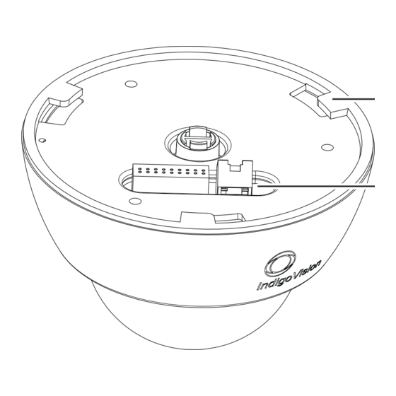
2 Hardware Description Enhanced SD Fixed Dome - 9000 Range Bayonet Fixing Point Connection Panel Figure 2: Internal variant - rear view Dimensions • Internal Dome: 155mm (d) x 110mm (h) Weight • 0.7kg (including packaging) Standard Vandal Resistant variant Camera... -
Page 11: Environmental Vandal Resistant Variant
Enhanced SD Fixed Dome - 9000 Range 2 Hardware Description Connection Panel Security Screw Figure 4: Standard Vandal Resistant variant - rear view (no exit collar) Dimensions • Without Exit Collar: 160mm (d) x 103mm (h) • With Exit Collar: 163mm (d) x 131mm (h) Weight •... -
Page 12: Connections
2 Hardware Description Enhanced SD Fixed Dome - 9000 Range Connection Panel Security Screw Figure 6: Environmental Vandal Resistant variant - rear view (no exit collar) Dimensions • 163mm (d) x 131mm (h) Weight • 1.3kg (including packaging) Connections The camera connections are situated on the back of the camera. -
Page 13: Binary Io Connections
Enhanced SD Fixed Dome - 9000 Range 2 Hardware Description After using the 2- way connector, ensure you tuck it under the cover to prevent it from obscuring the field of view of the camera. Binary IO connections The camera has 2 opto-isolated binary inputs and 1 opto-isolated binary output. The table below provides details of the binary IO connections on the 18-way IO connector. -
Page 14: Power Requirements
2 Hardware Description Enhanced SD Fixed Dome - 9000 Range R = [ 100 *( 48 - 1 ) - 1500 ] = 4700 - 1500 = 3200 ~ 3K Binary output The binary output consists of solid state relay contacts. The camera’s binary output contacts are normally open and can be set to open or closed using Control Center. - Page 15 Enhanced SD Fixed Dome - 9000 Range 2 Hardware Description Signal Recommended Wire Gauge Pin 10 IN2- 22 AWG Pin 11 CONSOLE RX 22 AWG Pin 12 CONSOLE TX 22 AWG Pin 13 GND (Audio Out Return) 22 AWG Pin 14...
- Page 16 2 Hardware Description Enhanced SD Fixed Dome - 9000 Range User Guide - v7...
-
Page 17: Getting Started
ETTING TARTED This chapter describes the initial steps required to start using your 9000 SD Fixed Dome. Package contents Before continuing, please check that you have been shipped the items listed for your device. Internal variant Figure 10: Internal variant package contents 1. -
Page 18: Standard Vandal Resistant Variant
3 Getting Started Enhanced SD Fixed Dome - 9000 Range Ensure you remove the packing material from inside the camera before operating the camera. Remove the Dome Bubble from by rotating it anti-clockwise to its end stop position and lift it off. -
Page 19: Environmental Vandal Resistant Variant
Enhanced SD Fixed Dome - 9000 Range 3 Getting Started • 1 x hole template Ensure you remove the packing material from inside the camera before operating the camera. Remove the camera bezel by unscrewing the three security screws situated around the dome bubble (use the Torx T10 bit supplied). -
Page 20: Powering Up The 9000 Sd Fixed Dome
3 Getting Started Enhanced SD Fixed Dome - 9000 Range Ensure you remove the packing material from inside the camera before operating the camera. First remove the camera bezel by unscrewing the three security screws situated around the dome bubble (use the Torx T10 bit supplied). Lift off the bezel, the dome bubble, and the lens shroud. -
Page 21: Initial Camera Configuration
When using an exit collar, use a 5-10mm diameter cable with a round section. A 24V DC, 500mA PSU with mains power lead can be ordered from IndigoVision, the base order code is 110004. Add -1 to the base order code for a UK IEC mains lead, -2 for a US IEC mains lead and -3 for an EU IEC mains lead. - Page 22 3 Getting Started Enhanced SD Fixed Dome - 9000 Range Fixed Dome CAT5 crossover cable Power supply Figure 14: Connecting the device and PC using a cross-over cable Alternatively, you can connect the unit and PC to the same PoE switch.
- Page 23 Network Time Server Address (if enabled on the Date & Time page) IndigoVision recommends that if you are using DHCP, you should configure the DHCP server to assign a given IP address based on the device’s MAC address. Also, if the device does not receive any response from the DHCP server it will default to using the network parameters supplied by the last completed DHCP request.
-
Page 24: Using The Console Port
Otherwise, poor network performance may be experienced. After you have entered the configuration data, click Submit to apply the changes. IndigoVision recommends that you make a note of the new IP address and subnet mask, or label the device with its new details. - Page 25 Enhanced SD Fixed Dome - 9000 Range 3 Getting Started Fixed Dome Serial cable PC with serial configuration software Camera connector 9 pin DSUB female mates to PC Console cable Standard serial cable Figure 17: Serial port connection 4. On the PC, use a Terminal Emulation program such as Windows HyperTerminal and set the serial port parameters as follows: •...
-
Page 26: Attaching The Device To The Network
3 Getting Started Enhanced SD Fixed Dome - 9000 Range You may need to change the Ethernet link type default value from Auto-negotiate for some network devices. If you have problems maintaining a network link, contact your system administrator to determine the appropriate setting. -
Page 27: Installation
NSTALLATION This section details how to install the 9000 SD Fixed Dome variants. Before installing the camera in its final position, you must first configure its IP settings. ► For more information, see "Initial camera configuration" on page 21 Installing the Internal variant Once you have configured your camera’s IP settings, you are ready to install it in its final position. -
Page 28: Run The Cabling To The Mounting Plate
4 Installation Enhanced SD Fixed Dome - 9000 Range 93.5 mm 58mm Figure 19: Mounting Plate dimensions 1. Use the profile template supplied with the camera to mark out the fixing holes and cable access point on the mounting surface. 2. Prepare the holes and make the cutout on the mounting surface, fitting appropriate mounting plugs. -
Page 29: Setting Up The Sensor
Enhanced SD Fixed Dome - 9000 Range 4 Installation 1. Connect the required cables to the Camera Assembly (5). 2. Attach the base of the Camera Assembly to the Mounting Plate (6) so that the three bayonet fixing points and interface connector area align correctly with the plate. -
Page 30: Focus Procedure
4 Installation Enhanced SD Fixed Dome - 9000 Range Ensure the 2-way analog connector is tucked it under the cover to prevent it from obscuring the field of view of the camera. 8. Re-fit the Dome Bubble fixing screw to lock the Dome Bubble to the Camera Assembly. - Page 31 Enhanced SD Fixed Dome - 9000 Range 4 Installation Wall/Ceiling preparation Before fitting the camera, drill fixing holes on the wall or ceiling for the camera, and cut out the cable access hole. 62.8mm 32.0mm 125.5mm Figure 22: Underside of Standard Vandal Resistant variant without exit collar 62.75mm...
- Page 32 4 Installation Enhanced SD Fixed Dome - 9000 Range Run the cabling to the access point When the wall or ceiling has been prepared, run the required cables up to the cable access hole. Fit the Camera Assembly 1. Connect the cables to the camera as required.
-
Page 33: With Exit Collar
Enhanced SD Fixed Dome - 9000 Range 4 Installation Ensure the 2-way analog connector is tucked it under the cover to prevent it from obscuring the field of view of the camera. 7. Re-fit the Bezel to secure the Dome Bubble to the Camera Assembly. To ensure a watertight seal, tighten the screws to a minimum of 15 Nm (11 lbs/ft) and maximum of 20 Nm (15 lbs/ft). - Page 34 4 Installation Enhanced SD Fixed Dome - 9000 Range 86.25mm Dia 163.0mm Central Point (cable exit from wall) 13.8mm 27.6mm Figure 25: Exit Collar wall/ceiling fixing points and access hole 1. Use the profile template supplied with the camera to mark out the fixing holes and cable access point on the mounting surface.
- Page 35 Enhanced SD Fixed Dome - 9000 Range 4 Installation Grommet collar Figure 26: Invert the center of grommet to create a collar around the cable Only use the cable to pierce the grommet. Do not use any other tools, for example, a screwdriver or scalpel.
- Page 36 4 Installation Enhanced SD Fixed Dome - 9000 Range Ensure the camera lens assembly does not obstruct the fan as this may reduce the effectiveness of the fan, and impair image quality in low light conditions. 1. Remove the three security screws fixing the Bezel (1) to the Camera Assembly (6).
-
Page 37: Installing The Environmental Vandal Resistant Variant
Enhanced SD Fixed Dome - 9000 Range 4 Installation ► For information about using a 9-22mm lens, see "Using a 9-22mm lens" on page 41 Installing the Environmental Vandal Resistant variant If installing the camera in temperatures below - 10°C please read the section “Low Temperature Start-Up”... -
Page 38: Connect The Heater Power Supply
4 Installation Enhanced SD Fixed Dome - 9000 Range 1. Use the profile template supplied with the camera to mark out the fixing holes and cable access point on the mounting surface. 2. Prepare the holes and make the cutout on the mounting surface, fitting appropriate mounting plugs. -
Page 39: Fit The Camera To The Exit Collar
Enhanced SD Fixed Dome - 9000 Range 4 Installation Connect the power supply to the heater via the terminal block inside the exit collar. Connect the “+’ve” power supply wire to the heater assemblies Red/Blue wires, and the “-’ve” power supply wire to the Black/Brown wires. -
Page 40: Focus Procedure
4 Installation Enhanced SD Fixed Dome - 9000 Range 4. Release the locking screw and rotate the Lens Assembly (5) to the required position. Secure the locking screw when done to fix the tilt and lens orientation. Take care not to over-rotate the camera lens assembly as this may result in the internal cables becoming disconnected. -
Page 41: Operations
PERATIONS This chapter describes common tasks required for the operation of the 9000 SD Fixed Dome. Using a 9-22mm lens N/∞ Figure 31: 9-22mm lens Due to the thickness of the vandal-resistant dome bubble, there may be some loss of focus when the dome bubble is fitted over a camera lens assembly that has already been focused. -
Page 42: Heater And Fan Operation
5 Operations Enhanced SD Fixed Dome - 9000 Range Ambient Temp. (°C) Warm-Up Time (minutes) above -10 These warm- up times will be applicable every time the Environmental Vandal Resistant variant is powered-up in ambient temperatures lower than -10°C. Heater and fan operation The heater/fan assembly MUST be powered at all times. -
Page 43: Configuration
To access the Web Configuration pages, enter the IP address of your device into a web browser. The Home menu is displayed. ® IndigoVision devices support Microsoft Internet Explorer (version 8 or higher recommended). The Analytics menu requires Sun JRE version 1.6 or later. -
Page 44: Date & Time
DNS Domain — (optional) Specify the DNS domain the device will use. Broadcast Address — Broadcast addresses are calculated automatically using your IP address and subnet mask to locate and access IndigoVision devices within a given range of network IP addresses. This value is read-only. -
Page 45: Video
White Balance — Specifies the method by which the camera determines color levels. IndigoVision recommends this should be left at automatic unless one of the fixed values provides a more accurate representation of the hues within a particular scene. -
Page 46: Profiles
6 Configuration Enhanced SD Fixed Dome - 9000 Range If you set this value too high, the camera may experience unstable exposure control. If you set this value too low, the image exposure update time may be too long. Flicker Reduction — (Advanced option) Reduces the effects of light flicker on the camera. -
Page 47: Encoder
Enhanced SD Fixed Dome - 9000 Range 6 Configuration for example, Profile 2 has a higher priority than Profile 1. When a profile activation event occurs, the current active profile is re-evaluated and may change. The profiles themselves, bit-rate, frame-rate etc., are defined in the Encoder menu. -
Page 48: Analytics
Enhanced SD Fixed Dome - 9000 Range ► For more information about ACF and ACF+, refer to the IndigoVision application note "Understanding ACF+" available from the IndigoVision website. Optimization — Where available, optimization enables you to select how video is streamed based on requirements. - Page 49 Enhanced SD Fixed Dome - 9000 Range 6 Configuration License Filter 1 Filter 2 Filter 3 Hooded Camera Activity Hooded Camera Motion 1FIL Activity Motion, Tripwire, or Counter Motion, Tripwire, Congestion, Counter flow, flow Hooded Camera Activity Congestion, or Hooded Motion, Tripwire, or Counter Flow...
- Page 50 6 Configuration Enhanced SD Fixed Dome - 9000 Range • Left-click a block to detect motion in that block. The block is shown in full color, and the red border changes to surround the area that is detecting motion. To select more than one block, left-click and drag the pointer over the blocks to detect.
-
Page 51: Audio
Enhanced SD Fixed Dome - 9000 Range 6 Configuration Audio Audio Output and Input Gain— These values depend on the sensitivity of the input/output devices you are using. Specify a number between 0 – 100, where 0 is the quietest value. -
Page 52: Events
If Active when streaming video is selected, commands received over the network to control the relay are still actioned. IndigoVision recommends that you use only one method to control the binary output relay either by a network application, using the Active when streaming video, or binary output mapping. -
Page 53: Network Security
If unsure, do not change this value from the default value of zero, otherwise the performance of the network may be compromised. Bandwidth Manager — If using IndigoVision's Bandwidth Manager as part of the overall system, the IP address of the Bandwidth Manager should be entered and Bandwidth Management enabled. -
Page 54: Remote Access
6 Configuration Enhanced SD Fixed Dome - 9000 Range SNMP Configuration Enable — Check this box to enable SNMP access to the device. By default, this setting is enabled. Community Strings — If SNMP is enabled, the following entries allow the SNMP Community Strings to be configured: •... -
Page 55: Firmware Upgrade
Identifier — To obtain a new license key, you must quote the Identifier to Sales Orders or your IndigoVision Supplier. Video License Key — Enter the text string provided by Sales Orders or your IndigoVision Supplier to upgrade the device with a view stream license. -
Page 56: Enabling And Disabling Web Configuration
6 Configuration Enhanced SD Fixed Dome - 9000 Range Enabling and disabling web configuration For security, it is possible to disable web configuration of the device. To do this it is necessary to obtain a login shell on the device (either using telnet or via a connection to the serial port.) Once logged in as "root", the web server that provides the configuration interface... -
Page 57: Hardware Specification
ARDWARE PECIFICATION This chapter details the hardware specifications for the 9000 SD Fixed Dome. Codec specification Video • 1Vp-p, 75ohm (PAL or NTSC) Video codec • ITU-T Standard H.264 Baseline Profile • User-configurable bit rate • User-configurable frame rate • “4:2:0”... -
Page 58: Input/Output
7 Hardware Specification Enhanced SD Fixed Dome - 9000 Range Dynamic Range WDR: 120dB Max, 102dB Typical Signal to noise ratio >50dB (AGC off) Gain control Automatic (50dB max) or fixed options via web page Scan mode Progressive Mirror mode Selectable via web page... -
Page 59: Network Connections
Enhanced SD Fixed Dome - 9000 Range 7 Hardware Specification • Signal Impedance: 75 ohms Network connections • RJ45 connector for connecting to the network. The network connection must be made using CAT5 (or higher spec) twisted pair cable. • Maximum cable length is 100 metres. The network cable must use straight through wiring. - Page 60 7 Hardware Specification Enhanced SD Fixed Dome - 9000 Range User Guide - v7...
-
Page 61: Optional Mount Components
PTIONAL OUNT OMPONENTS The following components are available to help install the Vandal Resistant dome. Mount components are sold separately. The weights provided do not include the camera. In-Ceiling flush mount The In-ceiling flush mount is available to help install the 9000 SD Fixed Dome in a false ceiling. -
Page 62: A Optional Mount Components
A Optional Mount Components Enhanced SD Fixed Dome - 9000 Range Bracket Wall mount The Bracket Wall mount is available to mount the 9000 SD Fixed Dome horizontally on a vertical wall. Wall Mount Bracket Exit Collar Figure 33: Bracket Wall mount... -
Page 63: Wall Mount
Enhanced SD Fixed Dome - 9000 Range Wall mount The Wall mount is available to help install the 9000 SD Fixed Dome as a pendant. Figure 34: Wall mount dimensions (1.4Kg) User Guide - v7... -
Page 64: Swan-Neck Mount
Enhanced SD Fixed Dome - 9000 Range Swan-Neck mount The Swan-Neck mount is available to help install the 9000 SD Fixed Dome as a pendant. Figure 35: Swan-Neck mount dimensions (2.2Kg) User Guide - v7... -
Page 65: Vertical Mount
Enhanced SD Fixed Dome - 9000 Range Vertical mount The Vertical mount is available to install the 9000 SD Fixed Dome as a pendant. Figure 36: Vertical mount dimensions (1.5Kg) User Guide - v7... -
Page 66: Npt Adapters
Enhanced SD Fixed Dome - 9000 Range NPT adapters The NPT adapters are optional components to fix the 9000 SD Fixed Dome to standard 1.5” NPT mounts. These can be used to fix the dome to existing mounts to save time during installation. -
Page 67: Corner Mount Adapter
Enhanced SD Fixed Dome - 9000 Range Corner Mount adapter The Corner Mount adapter is an optional component to fix a mount to the corner of walls. Dia 9.0mm(4) View on top face View in direction of ‘X’ 145.0mm 215.0mm View on right face View on front face Figure 38: Corner Mount adapter dimensions (0.5Kg) -
Page 68: Pole Mount Adapter
Enhanced SD Fixed Dome - 9000 Range Pole Mount adapter The Pole Mount adapter is an optional component to fix a mount to a pole. Figure 39: Pole Mount adapter User Guide - v7...
Need help?
Do you have a question about the 9000 Range and is the answer not in the manual?
Questions and answers