Hitachi SP 18VA Technical Data And Service Manual
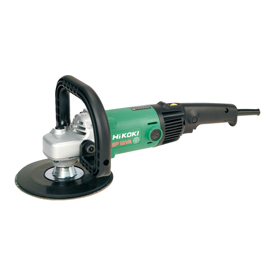
Electronic sander polisher
Hide thumbs
Also See for SP 18VA:
- Handling instructions manual (57 pages) ,
- Safety instructions and instruction manual (48 pages) ,
- Instruction manual (44 pages)

Related Manuals for Hitachi SP 18VA


Summary of Contents for Hitachi SP 18VA
- Page 1 MODEL SP 18VA POWER TOOLS TECHNICAL DATA ELECTRONIC SANDER POLISHER SERVICE MANUAL SP 18VA LIST No. 0352 Jun. 2002 SPECIFICATIONS AND PARTS ARE SUBJECT TO CHANGE FOR IMPROVEMENT...
- Page 2 REMARK: Throughout this TECHNICAL DATA AND SERVICE MANUAL, a symbol(s) is(are) used in the place of company name(s) and model name(s) of our competitor(s). The symbol(s) utilized here is(are) as follows: Competitor Symbol Utilized Model Name Company Name 9227C/9227CB MAKITA...
-
Page 3: Table Of Contents
9-5. Tightening Torque .......................... 11 9-6. Wiring Diagram ..........................11 9-7. Insulation Tests ..........................12 9-8. Gear Backlash Value ........................12 9-9. No-Load Current Value ......................... 12 10. STANDARD REPAIR TIME (UNIT) SCHEDULES ..............13 Assembly Diagram for SP 18VA... -
Page 4: Product Name
Hitachi Electronic Sander Polisher, Model SP 18VA [180 mm (7")] 2. MARKETING OBJECTIVE The Model SP 18VA has been developed to upgrade and replace the current Model SP 18V. The main improvements are increased motor power, weight reduction and improved operability. -
Page 5: Selling Point Descriptions
1) High-power motor and light weight The Model SP 18VA is equipped with high-power motor and is more powerful than the current Model SP 18V although it is compact and lightweight. We could say that the ratio of the motor's maximum output to the product's weight defines its performance. -
Page 6: Specifications
• • • • • • • • • • • • • • • • • • • • • • • • • • • • • • • • • • • • • • • • • • • • • • • • • • • • • • • • • • • • • • • • • • • • • • • • • • • • • • • • • • • • • • • • • • • • • • • • • • • • • • • • • • • • * Weight excludes cord, loop handle, rubber pad and washer nut. Relationship between dial settings and rotation speeds of the Model SP 18VA 4,000... -
Page 7: Comparisons With Similar Products
6. COMPARISONS WITH SIMILAR PRODUCTS 6-1. Specification Comparisons Maker HITACHI Model SP 18VA SP 18V Capacity disc dia. 180 (7") 180 (7") 180 (7") Input 1,250 1,100 1,200 Output* Max. output* 2,560 1,700 1,900 Rotation speed (no-load) /min. 0 --- 600/3,400... -
Page 8: Practical Test Data
6-2. Practical Test Data 1) Comparisons in torque vs. rotation speed 3500 SP 18VA (maximum speed) 3000 SP 18V (maximum speed) 2500 C (maximum speed) 2000 SP 18V (minimum speed) 1500 1000 SP 18VA (minimum speed) C (minimum speed) Torque (N •... -
Page 9: Precautions In Sales Promotion
7. PRECAUTIONS IN SALES PROMOTION In the interest of promoting the safest and most efficient use of the Model SP 18V Electronic Sander Polisher by all of our customers, it is very important that at the time of sale the salesperson carefully ensures that the buyer seriously recognizes the importance of the contents of the Handling Instructions, and fully understands the meaning of the precautions listed on the Caution Plate attached to each tool. -
Page 10: Function And Operation Of The Control Circuit
8. FUNCTION AND OPERATION OF THE CONTROL CIRCUIT 8-1. Control Circuit (Block Diagram) Switch Motor Triac AC power source Rotation speed detector Standard voltage F-V converter Phase control circuit circuit Variable resistor Differential Ramp generator amplifier Soft start and constant speed control circuit Load current detecting circuit Load current control circuit 8-2. -
Page 11: Motor Characteristics And Voltage Applied To The Motor
(6) Load current detecting circuit: Detects the load current by means of a low resistance resistor which is in series with the motor and the triac. (7) Load current control circuit: When the detected load is excessive (overload), this circuit sends a command (control signal) to reduce power to the motor. -
Page 12: Precautions In Disassembly And Reassembly
9. PRECAUTIONS IN DISASSEMBLY AND REASSEMBLY The [Bold] numbers in the descriptions below correspond to the item numbers in the Parts List and exploded assembly diagram for the Model SP 18VA. 9-1. Disassembly of the Armature Ass'y (1) Loosen the two Brush Caps [45], and take out the Carbon Brushes [46]. -
Page 13: Disassembly Of The Stator Ass'y
9-2. Disassembly of the Stator Ass'y (1) After taking out the Armature Ass'y [13], loosen the four Tapping Screws (W/Flange) D5 x 20 (Black) [51], and the two Tapping Screws (W/Flange) D4 x 20 (Black) [52] and remove Handle (A) [50] and Handle (B) [49]. (2) Disconnect the lead wires of the Stator Ass'y [16] from the Controller Switch [42]. -
Page 14: Reassembly
9-4. Reassembly Perform reassembly in the reverse order of disassembly while observing the given precautions and taking care of the following points. (1) After disassembly, thoroughly remove old grease from the inside of the Gear Cover Ass'y [5], and insert 25 g of new grease (Nippeco JF-375, Code No. -
Page 15: Insulation Tests
9-7. Insulation Tests On completion of disassembly after repair, measure the insulation resistance and conduct the dielectric strength test. Insulation resistance: 10 M or more with DC 500V megohm tester Dielectric strength test: AC 4,400 V for 1 minute, with no abnormalities 220 V --- 240 V •... -
Page 16: Standard Repair Time (Unit) Schedules
10. STANDARD REPAIR TIME (UNIT) SCHEDULES Variable MODEL 60 min. Fixed Work Flow SP 18VA Housing Ass'y Stator Ass'y General Assembly Armature Ass'y Gear Cover Ass'y Ball Bearing (6200DD) Ball Bearing (608VV) Dust Seal Felt Packing (B) Needle Bearing Gear... - Page 17 LIST NO. 0352 ELECTRIC TOOL PARTS LIST ELECTRONIC SANDER POLISHER 2002 • • Model SP 18VA (E1) 503 504...
- Page 18 PARTS SP 18VA ITEM CODE NO. DESCRIPTION REMARKS USED 303-255 SEAL LOCK SCREW (W/SP. WASHER) M4X10 305-507 TAPPING SCREW (W/FLANGE) D5X30 306-888 PUSHING BUTTON 306-889 SPRING 320-936 GEAR COVER ASS’Y INCLUD.3,4,18-21 315-055 SEAL RING (A) 315-054 WASHER (A) 939-540 RETAINING RING FOR D10 SHAFT (10 PCS.)
- Page 19 PARTS SP 18VA ITEM CODE NO. DESCRIPTION REMARKS USED 945-161 BRUSH CAP 999-043 CARBON BRUSH (1 PAIR) 958-900 BRUSH HOLDER 938-477 HEX. SOCKET SET SCREW M5X8 320-939 HANDLE (B) 320-938 HANDLE (A) 302-089 TAPPING SCREW (W/FLANGE) D5X20 (BLACK) 302-086 TAPPING SCREW (W/FLANGE) D4X20 (BLACK)
-
Page 20: Standard Accessories
SP 18VA STANDARD ACCESSORIES ITEM CODE NO. REMARKS DESCRIPTION USED 955-857 HEX. BAR WRENCH 8MM 937-913Z WRENCH 320-949 LOOP HANDLE 949-434 BOLT WASHER M10 (10 PCS.) 949-844 HEX. SOCKET HD. BOLT M10X20 (10 PCS.) 2 949-103 WOOL BONNET 180MM 1 EXCEPT FOR FRA,SUI,USA,CAN 314-090 SANDING DISCS 180MM C-P50 (10 PCS.)
Need help?
Do you have a question about the SP 18VA and is the answer not in the manual?
Questions and answers