Yamaha CDX-497 Service Manual
Hide thumbs
Also See for CDX-497:
- Owner's manual (228 pages) ,
- Owner's manual (78 pages) ,
- Owner's manual (28 pages)
Table of Contents
Advertisement
CDX-497/CDX-397
This manual has been provided for the use of authorized YAMAHA Retailers and their service personnel.
It has been assumed that basic service procedures inherent to the industry, and more specifically YAMAHA Products, are already
known and understood by the users, and have therefore not been restated.
WARNING:
IMPORTANT:
The data provided is believed to be accurate and applicable to the unit(s) indicated on the cover. The research, engineering, and
service departments of YAMAHA are continually striving to improve YAMAHA products. Modifications are, therefore, inevitable
and specifications are subject to change without notice or obligation to retrofit. Should any discrepancy appear to exist, please
contact the distributor's Service Division.
WARNING:
IMPORTANT:
I CONTENTS
TO SERVICE PERSONNEL ...................................... 2-4
FRONT PANELS ............................................................ 6
REAR PANELS .......................................................... 6-8
REMOTE CONTROL PANELS ...................................... 8
INTERNAL VIEW ........................................................... 9
........................................... 10
1 0 1 0 1 6
COMPACT DISC PLAYER
Failure to follow appropriate service and safety procedures when servicing this product may result in personal
injury, destruction of expensive components, and failure of the product to perform as specified. For these reasons,
we advise all YAMAHA product owners that any service required should be performed by an authorized
YAMAHA Retailer or the appointed service representative.
The presentation or sale of this manual to any individual or firm does not constitute authorization, certification or
recognition of any applicable technical capabilities, or establish a principle-agent relationship of any form.
Static discharges can destroy expensive components. Discharge any static electricity your body may have
accumulated by grounding yourself to the ground buss in the unit (heavy gauge black wires connect to this buss).
Turn the unit OFF during disassembly and part replacement. Recheck all work before you apply power to the unit.
........................................ 9
.............................. 10
2006
This manual is copyrighted by YAMAHA and may not be copied or
redistributed either in print or electronically without permission.
SERVICE MANUAL
IMPORTANT NOTICE
IC DATA ................................................................. 15-19
BLOCK DIAGRAM ....................................................... 20
WIRING DIAGRAM ...................................................... 21
PRINTED CIRCUIT BOARDS ................................ 22-24
SCHEMATIC DIAGRAMS ...................................... 25-26
REPLACEMENT PARTS LIST .............................. 28-29
REMOTE CONTROL .................................................... 30
All rights reserved.
.......... 11-12
.................................. 13-14
P.O.Box 1, Hamamatsu, Japan
'06.07
Advertisement
Table of Contents

Related Manuals for Yamaha CDX-497


Summary of Contents for Yamaha CDX-497
-
Page 1: Table Of Contents
This manual has been provided for the use of authorized YAMAHA Retailers and their service personnel. It has been assumed that basic service procedures inherent to the industry, and more specifically YAMAHA Products, are already known and understood by the users, and have therefore not been restated. -
Page 2: To Service Personnel
CDX-497/CDX-397 I TO SERVICE PERSONNEL AC LEAKAGE WALL EQUIPMENT TESTER OR 1. Critical Components Information OUTLET UNDER TEST EQUIVALENT Components having special characteristics are marked s and must be replaced with parts having specifications equal to those originally installed. 2. Leakage Current Measurement (For 120V Models Only) - Page 3 CDX-497/CDX-397 2) The laser power level can be adjusted with the VR on the pick-up PWB. However, this level has been set by the factory prior to shipping from the factory. Do not adjust this laser level control unless instruction is provided elsewhere in this manual.
- Page 4 CDX-497/CDX-397...
-
Page 5: Prevention Of Electrostatic Discharge
CDX-497/CDX-397 I PREVENTION OF ELECTROSTATIC DISCHARGE Some semiconductor (solid state) devices can be damaged easily by static electricity. Such components commonly are called Electrostatically Sensitive (ES) Devices. Examples of typical ES devices are integrated circuits and some field-effect transistors and semiconductor “chip” components. The following techniques should be used to help reduce the incidence of component damage caused by electro static discharge (ESD). -
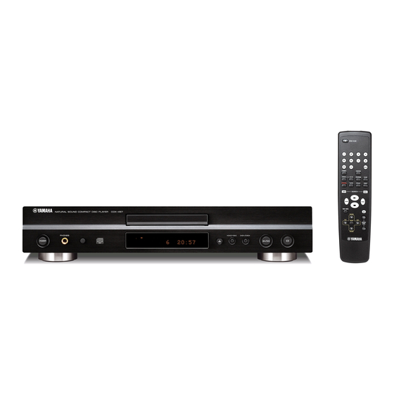
Page 6: Front Panels
CDX-497/CDX-397 I FRONT PANELS CDX-497 (R, T, K, A, B, G, J models) CDX-397 (R, T, A, B, G models) I REAR PANELS CDX-497 (R model) CDX-497 (T model) CDX-497 (K model) - Page 7 CDX-497/CDX-397 CDX-497 (A model) CDX-497 (B, G models) CDX-497 (J model) CDX-397 (R model) CDX-397 (T model)
-
Page 8: Remote Control Panels
CDX-497/CDX-397 CDX-397 (A model) CDX-397 (B, G models) I REMOTE CONTROL PANELS CDX-497 (R, T, K, A, B, G, J models) CDX-397 (R, T, A, B, G models) -
Page 9: Specifications
Titanium color ............R, B, G models Unit: mm (inch) I INTERNAL VIEW FRONT (5) P.C.B. (R model) FRONT (2) P.C.B. CD Mechanism MAIN (2) P.C.B. MAIN (1) P.C.B. FRONT (4) P.C.B. FRONT (3) P.C.B. (CDX-497 model) FRONT (1) P.C.B. -
Page 10: Repair Notes
CDX-497/CDX-397 I REPAIR NOTES / None of the components of the following unit can be supplied separately. Each unit must be replaced as a whole in case of a failure. • CD Mechanism • MAIN P.C.B. • FRONT P.C.B. I HOW TO MANUALLY EJECT THE TRAY / a. -
Page 11: Disassembly Procedures
→ Remove 2 screws. [56] (P.C.B. to bottom frame) → Remove 1 screw. [59] FRONT (3) P.C.B. [31 (3)] (P.C.B. to rear panel) → Remove 3 screws (CDX-497), (CDX-497 model) → Remove 1 screws. [54] 2 screws (CDX-397). [58] (P.C.B. to front panel ass'y) (P.C.B. - Page 12 CN43 (R model) CN52 FRONT (2) P. C. B. CN42 CD Mechanism CN41 (FRONT (2) P. C. B.) View A FRONT (4) P. C. B. FRONT (1) P. C. B. FRONT (3) P. C. B. Front Panel A'ssy (CDX-497 model)
-
Page 13: Test Mode
Check FL display. (*1) Icon (left) SPACE EEPROM write/read test. RANDOM Spindle servo on/off. Output level up. OUTPUT LEVEL + Icon (right) (CDX-497 model) Output level down. OUTPUT LEVEL - (CDX-497 model) Pattern 1 Pattern 2 Pattern 3 Pattern 4 Pattern 5... - Page 14 CDX-497/CDX-397 W W W W W D D D D D A A A A A F F F F F W W W W W D D D D D A A A A A F F F F F...
-
Page 15: Ic Data
CDX-497/CDX-397 I IC DATA IC21 : TC94A54 (MAIN P.C.B) IC21 : TC94A54 (MAIN P.C.B) Pin No. Pin name Description Remark RFZI Input pin for the RF ripple zero-cross signal. To be connected to the RFRP via * No replacement part available. - Page 16 CDX-497/CDX-397 IC21 : TC94A54 (MAIN P.C.B) IC21 : TC94A54 (MAIN P.C.B) Pin No. Pin name Pin name Function Remark Pin No. Pin name Description Remark VDDM – 1.5V supply voltage pin dedicated to the DSP/1Mbit SRAM – LPFN Pin for receiving an inverted output of the PLL-circuit low-pass The resistance side is connected.
- Page 17 CDX-497/CDX-397 IC22 : TA2125 (MAIN P.C.B) Motor driver * No replacement part available. Driver REG OUT N.C. Control STBY STBY Logic lref N.C. N.C. N.C. N.C. VCIN Symbol Function OUT5A Output terminal H-bridge Supply voltage terminal for Logic H-bridge OUT5B...
- Page 18 CDX-497/CDX-397 IC71 : CS4392 (MAIN P.C.B) * No replacement part available. (SDA/CDIN) (CL/CCLK) (AD0/CS) AMUTEC BMUTEC CMOUT FILT+ MODE SELECT EXTERNAL REFERENCE (CONTROL PORT) MUTE CONTROL VOLUME AOUTA+ CONTROL ∆∑ INTERPOLATION ANALOG FILTER FILTER AOUTA- SERIAL SCLK MIXER PORT LRCK AOUTB- ∆∑...
- Page 19 CDX-497/CDX-397 IC71 : CS4392 (MAIN P.C.B) Symbol Function Reset (Input) - Powers down device and resets all intemal registers to their default settings. Logic Power (Input) - Positive power for the digital input/output. SDATA Serial Audio Data (Input) - Input for two’s complement serical audio data.
-
Page 20: Block Diagram
CDX-497/CDX-397 I BLOCK DIAGRAM X501 IC22 IC51 X201 IC21 CD Mechanism CDX-497 model FL51 COAXIAL IC75 JK75 RS51 OPTICAL IC41 JK52 D401, 403 IC71 T401 IC73 JK73 IC74 IC42 D402, 404 IC43 IC44 D405, 406 IC72 IC45 Q401 • See page 26 →... -
Page 21: Wiring Diagram
CDX-497/CDX-397 I WIRING DIAGRAM R model CDX-497 model FRONT (5) MAIN (2) VOLTAGE/SELECTOR MAIN (1) AGND AGND P_MUTE P_MUTE PWR_ON PWR_ON AGND MGND MGND PWR_ON ST+5V ST+5V FLT_ON 13 FLT_ON (VP_ON) CDX-497 model FRONT (2) Power Control FRONT (3) Phones... -
Page 22: Printed Circuit Boards
FOR INFORMATION ONLY (NO SERVICE PARTS WILL BE AVAILABLE) MAIN (1) P.C.B. DIGITAL OUT MAIN (2) P.C.B. (Top view) (Top view) LINE OUT COAXIAL OPTICAL CDX-497 model MAIN (2) (CN43) MAIN (1) (CN42) FRONT (2) (CN41) CDX-497 model CDX-497 model... - Page 23 CDX-497/CDX-397 MAIN (1) P.C.B. MAIN (2) P.C.B. (Bottom view) (Bottom view) CDX-497 model...
- Page 24 CDX-497/CDX-397 FRONT (1) P.C.B. (Top view) MAIN (1) (CN52) FRONT (2) P.C.B. FRONT (3) P.C.B. (Top view) (Top view) CDX-497 model FRONT (4) (BN42) PHONES MAIN (1) FRONT (5) (BN43) (CN41) (R model) T, K, A, B, G, J models...
- Page 25 FOR INFORMATION ONLY (NO SERVICE PARTS WILL BE AVAILABLE) MAIN To CD Machanism MAIN (1) MAIN (2) To CD Machanism To CD Machanism OPTICAL DIGITAL OUT CDX-497 model COAXIAL AUDIO OUT CDX-497 model Page 26 to FRONT (3)_BN71 Page 26 Page 26 to FRONT (1)_CN52...
- Page 26 CDX-497/CDX-397 FRONT Page 25 to MAIN (1)_CN52 Page 25 to MAIN (1)_CN71 FRONT (1) FRONT (3) CDX-497 model Page 25 to MAIN (1)_CB41 AC IN T, K, A, B, G, J models FRONT (4) POWER ON/OFF FRONT (5) PHONES R model...
- Page 27 CDX-497/CDX-397 MEMO MEMO MEMO MEMO...
-
Page 28: Replacement Parts List
CDX-497/CDX-397 I REPLACEMENT PARTS LIST R model CDX-497 model 31 (5) R model CDX-497 CDX-397 model model 38-1 35 (2) 31 (2) CDX-497 model 31 (4) Note) The replacement battery cover is not available. 31 (3) CDX-497 model 35 (1) - Page 29 CDX-497/CDX-397 WARNING G Components having special characteristics are marked s and must be replaced with parts having specifications equal to those originally installed. ✻ New Parts ✻ New Parts...
-
Page 30: Remote Control
H H H H H FOLDER + OUTPUT LEVEL + 79-1D 79-6C Q Q Q Q Q FILE - ENTER 79-3F CDX-497 model W W W W W 79-6B FILE + 79-6A G G G G G FOLDER - OUTPUT LEVEL - 79-1C...
Need help?
Do you have a question about the CDX-497 and is the answer not in the manual?
Questions and answers