Table of Contents
Advertisement
Power Max
Model No. 38614—Serial No. 311000001 and Up
Model No. 38624—Serial No. 311000001 and Up
Model No. 38624W—Serial No. 311000001 and Up
Model No. 38634—Serial No. 311000001 and Up
Model No. 38644—Serial No. 311000001 and Up
Model No. 38654—Serial No. 311000001 and Up
Introduction
This machine is intended to be used by residential
homeowners or professional, hired operators. It is
designed for removing snow from paved surfaces,
such as driveways and sidewalks, and other surfaces
for traffic on residential or commercial properties.
It is not designed for removing materials other
than snow, nor is a model with a pivoting scraper
designed for clearing off gravel surfaces.
Read this information carefully to learn how to operate
and maintain your machine properly and to avoid injury
and machine damage. You are responsible for operating
the machine properly and safely.
You may contact Toro directly at www.Toro.com for
machine and accessory information, help finding a
dealer, or to register your machine.
Whenever you need service, genuine Toro parts, or
additional information, contact an Authorized Service
Dealer or Toro Customer Service and have the model
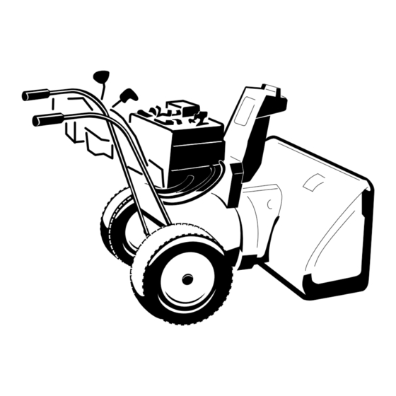
and serial numbers of your machine ready. Figure 1
identifies the location of the model and serial numbers
on the machine. Write the numbers in the space
provided.
Figure 1
1. Model and serial number location
© 2010—The Toro® Company
8111 Lyndale Avenue South
Bloomington, MN 55420
®
Snowthrowers
Model No.
Serial No.
This manual identifies potential hazards and has
safety messages identified by the safety alert symbol
(Figure 2), which signals a hazard that may cause serious
injury or death if you do not follow the recommended
precautions.
1. Safety alert symbol
This manual uses 2 words to highlight information.
Important calls attention to special mechanical
information and Note emphasizes general information
worthy of special attention.
contains chemicals known to the State of
California to cause cancer, birth defects,
This spark ignition system complies with Canadian
ICES-002.
The enclosed Engine Owner's Manual is supplied
for information regarding the US Environmental
Protection Agency (EPA) and the California
Emission Control Regulation of emission systems,
maintenance, and warranty. Replacements may be
ordered through the engine manufacturer.
Register at www.Toro.com.
Form No. 3365-702 Rev A
Figure 2
WARNING
CALIFORNIA
Proposition 65 Warning
The engine exhaust from this product
or other reproductive harm.
Operator's Manual
Original Instructions (EN)
Printed in the USA
All Rights Reserved
Advertisement
Table of Contents


Need help?
Do you have a question about the 38614 and is the answer not in the manual?
Questions and answers