Table of Contents
Advertisement
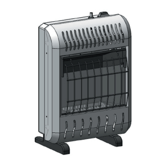
UNVENTED (VENT-FREE) BLUE FLAME GAS HEATER
SAFETY INFORMATION AND INSTALLATION MANUAL
Model:
BWH10NLM
WARNING: If the information in this manual is not followed exactly, a fi re or
explosion may result causing property damage, personal injury or loss of life.
— Do not store or use gasoline or other fl ammable vapors and liquids in the
vicinity of this or any other appliance.
— WHAT TO DO IF YOU SMELL GAS
• Do not try to light any appliance.
• Do not touch any electrical switch; do not use any phone in your building.
• Immediately call your gas supplier from a neighbor's phone. Follow the gas
supplier's instructions.
• If you cannot reach your gas supplier, call the fi re department.
— Installation and service must be performed by a qualifi ed installer, service
agency or the gas supplier.
INSTALLER: Leave this manual with the appliance.
CONSUMER: Retain this manual for future reference.
Model:
BWH20NLTB
Model:
BWH30NLTB
Advertisement
Table of Contents

Related Manuals for Sure Heat BWH10NLM


Summary of Contents for Sure Heat BWH10NLM
- Page 1 UNVENTED (VENT-FREE) BLUE FLAME GAS HEATER SAFETY INFORMATION AND INSTALLATION MANUAL Model: BWH10NLM Model: BWH20NLTB Model: BWH30NLTB WARNING: If the information in this manual is not followed exactly, a fi re or explosion may result causing property damage, personal injury or loss of life.
-
Page 2: Table Of Contents
TABLE OF CONTENT Safety Information ..........2 Troubleshooting..........21 Local Codes............4 Specifi cations ..........25 Product Identifi cation ........4 Wiring Diagrams ..........25 Unpacking............4 Replacement Parts ..........26 Air For Combustion and Ventilation ....5 Service Hints ..........29 Installation ............ - Page 3 SAFETY INFORMATION Surface of heater becomes very hot when running heater. Keep children continued and adults away from hot surface to avoid burns or clothing ignition. DANGER: Carbon monoxide poisoning may lead to death! Heater will remain hot for a time after shut-down.
-
Page 4: Local Codes
SAFETY INFORMATION Product Continued Identifi cation 8. Do not run heater • where fl ammable liquids or vapors are Control Knob Ignitor Button Switch used or stored • under dusty conditions 9. Before using furniture polish, wax, carpet cleaner or similar products, turn heater off. If heated, the vapors from these products may create a white powder residue within burner box or on adjacent walls or furniture. -
Page 5: Air For Combustion And Ventilation
Unusually Tight Construction AIR FOR COMBUSTION The air that leaks around doors and windows AND VENTILATION may provide enough fresh air for combustion and ventilation. However, in buildings of un- usually tight construction, you must provide WARNING: This heater shall additional fresh air. -
Page 6: Air For Combustion And Ventilation
AIR FOR COMBUSTION _______ Btu/Hr (maximum can support) _______ Btu/Hr (actual amount)Example: AND VENTIlATION 51,200 Btu/Hr (maximum the Continued space can support) 60,000 Btu/Hr (actual amount of DETERMINING FRESH-AIR FLOW Btu/Hr used) FOR HEATER LOCATION The space in the above example is a confi ned Determining if you Have a Confi... - Page 7 AIR FOR COMBUSTION INSTALLATION AND VENTILATION NOTICE: This heater is intended Continued for use as supplemental heat. Use this heater along with your p r i m a r y h e a t i n g s y s t e m . D o not install this heater as your primary heat source.
-
Page 8: Installation
INSTALLATION CAUTION: This heater creates Continued warm air currents. These currents INSTALLATION ITEMS move heat to wall surfaces next to Before installing heater, make sure you have the items listed below. heater. Installing heater next to vinyl • for propane/LP gas, external regulator or cloth wall coverings or operating (supplied by installer) heater where impurities (such as,... - Page 9 3. Remove tape and mounting bracket from Shell Panel wall. Screws Figure 7 - Mounting Bracket Clearances Figure 6 - Removing Shell Front Of Heater ITEM NO. BWH10NLM BWH20NLTB BWH30NLTB Methods For Attaching Mounting Bracket 8" 12" 16" To Wall 11"...
- Page 10 INSTALLATION Placing Heater On Mounting Bracket 1. Locate two horizontal slots on back panel Continued of heater. Attaching Mounting Bracket To Wall 2. Place heater onto mounting bracket. Slide Note: Wall anchors, mounting screws and horizontal slots onto stand-out tabs on spacers are in hardware package.
- Page 11 INSTALLATION Continued Base Foot Screws Sheet Metal Figure 12 - Installing Base Feet Figure 11-Installing Bottom Mounting Screws Mounting Base Feet to Heater Note: A 90° elbow is required for mounting this unit and must be installed BEFORE base feet to provide proper clearance (see Figure 14, page 12).
- Page 12 INSTALLATION Continued WARNING: This appliance requi- res a 3/8” NPT (National Pipe Thread) inlet connection to the pressure regulator. WARNING: A qualifi ed service Figure 13 - External Regulator With Vent person must connect heater to gas Pointing Down supply. Follow all local codes. WARNING: For natural gas, never connect heater to private (non-utility) gas wells.
- Page 13 INSTALLATION CAUTION: For propane/LP gas, Continued make sure external regulator has been Installation must include equipment shutoff installed between propane/LP supply valve, union and plugged 1/8" NPT tap. Locate and heater. See guidelines under NPT tap within reach for test gauge hook up. Connecting to Gas Supply, page 12.
- Page 14 INSTALLATION CONNECTING TO ELECTRICAL SUPPLY (Only for BWH20NLTB and Continued BWH30NLTB) PRESSURE TESTING HEATER GAS CONNECTIONS WARNING: Fan accessory must 1. Open equipment shutoff valve (see Figure be grounded. Fan comes with a three- 15, page 13). prong, grounding plug as shown in 2.
- Page 15 INSTALLATION WARNING: Only a qualified installer Continued or service technician can perform gas selection and connecting to gas supply. LP to NG Conversion Operation 1. Before gas conversion, remove knob lock by removing screw. (See Figure 19 & 20) 2. The knob is in the LP position (See Figure 23 on page 16).
- Page 16 INSTALLATION WARNING: Only a qualified installer Continued or service technician can perform gas selection and connecting to gas supply. NG to LP Conversion Operation 1. Before gas conversion, remove knob lock by removing screw. (See Figure 19 & 20) 2. Before changing, the knob is in the NG position (See Figure 22).
-
Page 17: Operating Heater
D. Do not use this appliance if any part has to desired heating level (Model been under water. Immediately call a BWH10NLM is with only one heating qualifi ed service technician to inspect the level). The burner should light. Set control... - Page 18 OPERATING HEATER THERMOSTAT CONTROL OPERATION Continued (Only for BWH20NLTB and BWH30NLTB) The thermostatic control used on these models differs from standard thermostats. Standard thermostats simply turn the burner on and off the burner. The thermostat used on this heater senses the room temperature. At times, the room may exceed the set temperature.
-
Page 19: Inspecting Heater
INSPECTING HEATER BURNER FLAME PATTERN Check pilot flame pattern and burner flame WARNING: If yellow tipping occ- patterns often. urs, your heater could produce PILOT FLAME PATTERN Figure 27 shows a correct pilot flame pattern. increased levels of carbon monoxide Figure 28 shows an incorrect pilot flame pat- tern. -
Page 20: Cleaning And Maintenance
1. Shut off the unit, including the pilot. Allow CLEANING AND the unit to cool for at least thirty minutes. MAINTENANCE 2. Inspect burner pilot for dust and dirt. 3. Blow air through the ports/slots and holes in the burner. WARNING: Turn off heater and let 4. -
Page 21: Troubleshooting
TROUBLESHOOTING WARNING: Turn off and unplug heater and let cool before servicing. Only a qualifi ed service person should service and repair heater. CAUTION: Never use a wire, needle or similar object to clean ODS/pilot. This can damage ODS/pilot unit. Note: All troubleshooting items are listed in order of operation. - Page 22 TROUBLESHOOTING Continued OBSERVED PROBLEM OSSIBLE CAUSE REMEDY 1. Press in control knob fully 1. Control knob not fully ODS/pilot lights but flame 2. After ODS/pilot lights, keep pressed in goes out when control knob control knob pressed in 30 2. Control knob not pressed is released seconds in long enough...
- Page 23 TROUBLESHOOTING Continued OBSERVED PROBLEM POSSIBLE CAUSE REMEDY Yellow fl ame during burner 1. Check burner for dirt and 1. Not enough air combustion debris. If found, clean 2. Gas regulator defective burner (see Cleaning and 3. Clogged or dirty burner Maintenance, page 18) 2.
- Page 24 TROUBLESHOOTING Continued WARNING: If you smell gas • Shut off gas supply. • Do not try to light any appliance. • Do not touch any electrical switch; do not use any phone in your building. • Immediately call your gas supplier from a neighbor’s phone. Follow the gas supplier’s instructions.
-
Page 25: Specifi Cations
SPECIFICATIONS ITEM NO. BWH10NLM BWH20NLTB BWH30NLTB Gas Type Using Natural Gas Pressure Regulator Setting 4.5 in. W.C. 4.5 in. W.C. 4.5 in. W.C. Inlet Gas Pressure (inches of water) For purposes of input adjustment Maximum 10.5 in. 10.5 in. 10.5 in. -
Page 26: Replacement Parts
Replacement Parts Model: BWH10NLM Part Description Part NO. Qty. Shell Front FCSHBF09001 Grill FCSHBF09002 Glass FCSHBF09003 Burner Assembly FCSHBF09004 Dual Fuel Regulator FCSHBF09005 Dual Fuel ODS Pilot FCSHBF09006 Base Foot FCSHBF09007 Selection Valve FCSHBF09008 Selection Valve Knob FCSHBF09009 Mounting Bracket... - Page 27 Replacement Parts Model: BWH20NLTB Part Description Part NO. Qty. Shell Front FCSHBF09014 Grill FCSHBF09015 Glass FCSHBF09016 Burner Assembly-BF20 FCSHBF09017 Dual Fuel Regulator FCSHBF09005 Dual Fuel ODS Pilot FCSHBF09006 Base Foot FCSHBF09007 Selection Valve FCSHBF09018 Selection Valve Knob FCSHBF09009 Mounting Bracket FCSHBF09019 Thermo Valve Assembly FCSHBF09031...
- Page 28 Replacement Parts Model: BWH30NLTB Part Description Part NO. Qty. Shell Front FCSHBF09026 Grill FCSHBF09027 Glass FCSHBF09028 Burner Assembly FCSHBF09029 Dual Fuel Regulator FCSHBF09005 Dual Fuel ODS Pilot FCSHBF09006 Base Foot FCSHBF09007 Selection Valve FCSHBF09030 Selection Valve Knob FCSHBF09009 Mounting Bracket FCSHBF09019 Thermo Valve Assembly FCSHBF09031...
-
Page 29: Service Hints
Products’ Technical Service web site at If they can’t supply original replacement www.sureheat.com. part(s), either contact your nearest Parts Central (see page 7) or call Sure Heat Heating Products at (800) 229-5647 for referral information. When calling Sure Heat, have ready: •... -
Page 30: Limited Warranty
Sure Heat Mfg. warrants that the components of this appliance are warranted free from defects in material and workmanship for two (2) years from the date of purchase. Sure Heat Mfg. at its option, will repair or replace this product or any component of the product found to be defective during the warranty period.
Need help?
Do you have a question about the BWH10NLM and is the answer not in the manual?
Questions and answers