
Related Manuals for LG PS-N550WPR


Summary of Contents for LG PS-N550WPR
- Page 1 Website http://biz.lgservice.com AIR PURIFIER SERVICE MANUAL MODEL: PS-N550WP CAUTION BEFORE SERVICING THE UNIT, READ THE SAFETY PRECAUTIONS IN THIS MANUAL. February, 2007 Printed in Korea P/NO : MFL31520605...
- Page 2 Safety instructions SECTION PAGE 3~5 Logics SECTION PAGE 6 Major Specifications of each SECTION Model PAGE 7 Operations/Functions Manual SECTION PAGE 8~16 Main Components SECTION Disassemble/Assemble and Repair Instruction PAGE 17~24 SECTION Electric diagram PAGE 25 SECTION Troubleshooting and inspection direction PAGE 26~30 SECTION...
-
Page 3: Safety Instructions
Safety instructions For your safety, the information in this manual must be followed to minimize the risk of fire or explosion, electric shock, or to prevent property damage, personal injury, or death. Warning / Caution Warning : This symbol will alert you to hazards or unsafe practices which could cause bodily injury or property damage. - Page 4 Safety instructions In-Use Make sure the power cord is plugged firmly and completely into the outlet. Do not operate with wet hands. If the power cord ever becomes frayed or damaged, do not attempt to repair. The cord should be replaced by a qualified technician.
- Page 5 Safety instructions Caution When Installation When using the unit, maintain a distance of at least 3 feet between the Air Purifier and any Television or audio product. Avoid installing the Air Purifier in direct sunlight and never operate the unit near or around open flames or other heat sources.
- Page 6 Logics Terminology Filters Introduction 1-1. Negative ion (1) Pre-Filter One filter performs antibiotic treatment, anti mold (1) What is a negative ion? treatment, and dust removal, providing a purified Atomic element in the air with negative electrons air. that releases a refreshing feeling. It can be found in a forest, waterfalls, thermal spring and etc.
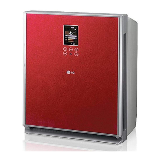
- Page 7 Major specifications on each model Model name PS-N550WPR Power Supply 120V~60Hz Measurement(W H D) 426mm 568mm 271mm Application Space Weight 12.0kg Color Design Easy design for convenient operation Power usage 55W(Turbo) Noise Turbo(47dB) Wind speed(CMM) Turbo(6.4CMM) Negative ion Generation Generate 1million super negative ions...
-
Page 8: Display And Controller
Operations/Functions Manual Spare part Name Mainframe Safty Net: The inside of air outlet Filter case (Allergen filter + HEPA filter + deodorizing filter) Odor sensor Photo-Catalyst Plasma Filter Dust Sensor Pre-filter Front panel Power Plug Display and controller Operation mode indicator Fan speed indicator Negative ion/ sterilization Operation indicator... -
Page 9: Remote Controller
Allow the filter to dry completely before reinstalling. If not completely dried, it may cause the air purifier to malfunction or cause bad odors to be emitted during use. A replacement filter (Anti-Allergic Filter) can be purchased at an LG service center. -
Page 10: Battery Installation
• Remove batteries when the air purifier is stored for extended periods of time. • If controller fails to work after new batteries are installed, contact an LG service center for service. -10-... -
Page 11: Operation Mode
Operations/Functions Manual Operation Mode Air Purifying Operation Purify Indoor Air Power ON/OFF Turns the air purifier on and off. Press once to turn on, again to turn it off. A confirmation tone will sound to indicate that the unit is powering on or turning off. The unit will also produce a tone when the unit is first plugged in. -
Page 12: Yellow Sandstorm Mode
Operations/Functions Manual Yellow Sandstorm Mode Purifies indoor air even in extreme conditions such as a sandstorm Power ON/OFF Switch to sandstorm mode by pressing the mode button. The correct fan speed will automatically be selected by the unit. The consumer can increase the fan speed to the next highest level by depressing the fan speed button. -
Page 13: Additional Function
Operations/Functions Manual Additional Function Off timer mode function Automatically shuts down after a preset amount of time Example:shut down automatically after 3 hours Power ON/OFF Allows you to set a delay from 1 to 9 hours that will turn the air purifier off automatically. -
Page 14: Filter Checking Function
Operations/Functions Manual Filter Checking Function May remind users to clean or replace the filter after use for a certain period. Filter self check light indicates to check filter. Power ON/OFF to shut the unit off. Open front panel to remove filter. Check filter, clean if necessary. (see page 15 to clean filter). -
Page 15: Filter Cleaning
Operations/Functions Manual Filter Cleaning • The prefilter should be cleaned on a monthly basis. • Check the filter when the filter indicator light is on. Turn unit off and unplug before cleaning. Grasp the grips on the front panel, pull forward to open. Remove the filter from the mainframe. -
Page 16: Maintenance
Operations/Functions Manual Maintenance Remove plug from grounded outlet. Clean and protect the air purifier's mainframe. Cover the air purifier when storing for an extended period of time. Clean with a soft cloth and mild detergent. Exterior case may scratch easily -16-... - Page 17 Major components Disassemble Assemble and Repair instruction Please read this before you disassemble Please unplug the power before disassemble. 1. Most components are connected with bolts or mounted on the other parts. Please disassemble according to the instruction. 2. Please do not disassemble unless it is absolutely necessary. Do not disassemble any part that is not on the disassemble instruction.
- Page 18 Major components Disassemble Assemble and Repair instruction 3. FAN is disassembled by holding and pulling fan. 4. Please remove 3 screws from the Motor Cover using a Screw Driver(+). 5. Remove the Motor Cover. Take out the Motor. Please be careful not to damage the Motor wire when removing the motor.
- Page 19 Major components Disassemble Assemble and Repair instruction When replacing the display PCB and the touch key 1. Open the door assembly 2. Loosen the screws on the back of the display cover (3 positions) Disconnect one wire and 2 connectors When removing the display cover, disconnect a touch key connector 3.
- Page 20 Major components Disassemble Assemble and Repair instruction How to replace the tempered glass and the touch 1. Open the door assembly 2. Loosen the screw (1 position) Open the cover and disconnect one wire and 2 connectors Remove the door assembly by pulling up. 3.
- Page 21 Major components Disassemble Assemble and Repair instruction 4. Loosen the screws (3 positions). Remove the plate iron Remove the deco cover (Top) 5. Remove the side deco by pushing up. Remove the tempered glass (When removing, disconnect a connector) Be careful not to lose the magnet indicated in the figure.
- Page 22 Major components Disassemble Assemble and Repair instruction How to replace gas & dust sensor, HVB assembly, micro switch and cover terminal 1. After disassembling the door assembly, remove the filter. Loosen the screws of 6 positions When removing the front case assembly, disconnect the connectors on positions.
- Page 23 Major components Disassemble Assemble and Repair instruction How to replace the guide filter, bracket, and magnet assembly 1. Loosen the screws of 6 positions on the front case assembly. 2. When removing the front cover, the guide filter is removed. When removing the screws of 2 positions on the front case, the bracket is removed.
- Page 24 Major components Disassemble Assemble and Repair instruction How to replace the power PCB 1. After disassembling the door assembly, remove the filter. Loosen the screws of 6 positions. 2. Loosen the screw (1 position) attached on the control PCB case using a screw driver.
-
Page 25: Electric Diagram
Electric diagram -25-... - Page 26 Troubleshooting and inspection direction Please take a look at the panel arrangement and the circuit drawing. Complete Malfunction Is input AC voltage • Make sure that power line is plugged in being supplied to both Power • Check the fuse in Power PCB ASM FUSE. PCB ASM C01 terminals? Is DC voltage on both Power •...
- Page 27 Troubleshooting and inspection direction LED Display Malfunction Are MAIN PCB ASM • Check CN-ACDC connection and Power PCB ASM CONECTOR correctly connected? Is voltage on both C01 terminals • Replace Power PCB ASM. of MAIN PCB ASM 12V? Replace MAIN PCB ASM. Dust &...
- Page 28 Troubleshooting and inspection direction Fan Malfunction FAN indicator on LED DISPLAY? • Check FILTER S/W contact Is the voltage of • Replace POWER PCB ASM. POWER PCB CN-MOTOR PIN 1~4 310V? Is the POWER • Check CN-MOTOR connection. PCB ASM CN-MOTOR CONNECTOR (Check after power-off) plugged in properly? Is the CN-ACDC...
- Page 29 Troubleshooting and inspection direction Negative Ion/Positive Ion generation malfunction IS NPI(Negative ion/Positive ion) • Select Negative ion/Positive ion. Selected? Are POWER PCB ASM • Check CN-ACDC connection. and MAIN PCB CONECTOR correctly connected? Is the power of • Replace MAIN PCB ASM. POWER PCB ASM CN-ACDC PIN2&8 (Negative Ion) and PIN2&9 (Positive Ion) AC220V?
- Page 30 Troubleshooting and inspection direction Not able to set product function with a remote control. Does an alarm occur when • Check batteries of remote controller. you operate the keys on the remote control? • Check MAIN PCB ASM CN-REC Is the power of CN-REC 1&2 DC+5V? connection Replace MAIN PCB ASM.
- Page 31 PCB Circuit Diagram/Parts Layouts DC PART Parts Layouts (Top View) DC PART Parts Layouts (Bottom View) -31-...
- Page 32 PCB Circuit Diagram/Parts Layouts DC PART Circuit Diagram -32-...
- Page 33 PCB Circuit Diagram/Parts Layouts Touch Key Circuit Diagram -33-...
-
Page 34: Exploded View
#EV# Exploded View/ Svc Components inventory Exploded View MODEL : PS-N550WP 7MDSAA 6EADWA 7MBNCF 2EBFAA 7ADQDA 2MBNFA 7ADQHA 2EBDSD 2MCKTA 7ADQAL 2EAYDC 2MCKSA 7MDJPA 2RABAA 2MCKCF 7ADAPA 7MDJPB 2EBDSG 2MJPAA 2MGJCA 1MJPAA 1MCKDU 1MCKDP 6EADTB 1MCQAA 1MCVSP 1MDQDL 6EADTC 2MEAGF 2MAZFA 1EBRPA 1MDQDR... - Page 35 -37-...
Need help?
Do you have a question about the PS-N550WPR and is the answer not in the manual?
Questions and answers