Infinity BassLink Service Manual
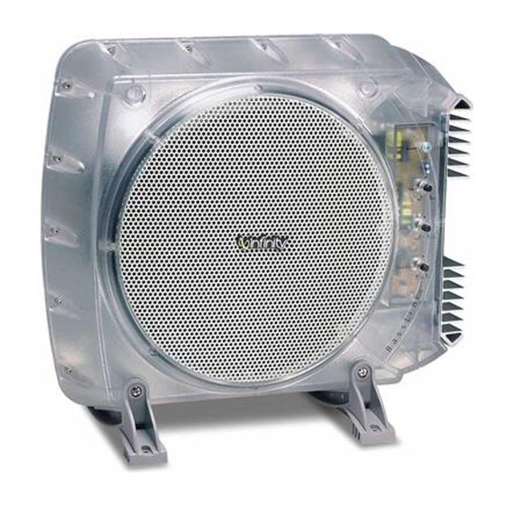
Powered automotive subwoofer
Hide thumbs
Also See for BassLink:
- Service manual (56 pages) ,
- User manual (8 pages) ,
- Instructions manual (8 pages)

Related Manuals for Infinity BassLink


Summary of Contents for Infinity BassLink
- Page 1 Models: BassLink BassLink (Remote Level Control Ready) BassLink X Powered Automotive Subwoofer SERVICE MANUAL Infinity Systems, Inc. 250 Crossways Park Dr. Woodbury, New York 11797 Rev 0 10/2001...
-
Page 2: Table Of Contents
BLOCK DIAGRAM …………..……………..………….………………….13 PCB DRAWINGS …………………………….……………………………14 ELECTRICAL PARTS LIST ………………………………………………24 SCHEMATICS …………………………………………………………..…29 PACKAGING …………………………………………………………….…31 BASSLINK or BASSLINK X (Versions with Remote Level Control jack) EXPLODED VIEW ………………………….…………………..…………33 MECHANICAL PARTS LIST …………….….……………………………34 BLOCK DIAGRAM ………………………..………….…………………...35 PCB DRAWINGS …………………………….……………………………36 ELECTRICAL PARTS LIST ………………………………………………43 SCHEMATICS …………………………………………………………..…49... -
Page 3: Specifications
Signal-Noise Ratio 65dB (Wide band w/ 22K LPF) Max Gain Level Noise 3.0 mV Basslink (Level pot Max.) 1.8 mV Basslink w/ Remote Level Control 1.8 mV Basslink X Max Gain Level Noise 2.0 mV Basslink (Level pot Min.) 1.7 mV Basslink w/ Remote Level Control 1.7 mV Basslink X... -
Page 4: Connections/Applications
Note: For the original version Basslink without the AUTO OFF/ON switch and Optional Sub Level Control, references to these items in the Connections, Applications and Controls sections can be ignored - all other information is valid. OWER ONNECTIONS PPLICATIONS Connect power to BassLink, as shown in Figure 5. - Page 5 PPLICATIONS CONTINUED Figure 7. BassLink audio connections for a head Figure 8. BassLink audio connections for a head unit equipped with four line-level (RCA) outputs. unit equipped with two line-level (RCA) outputs and two speaker-level outputs. FRONT FRONT REAR AUTO...
- Page 6 PPLICATIONS CONTINUED Figure 9. BassLink audio connections for a head Figure 10. BassLink audio connections for a head unit equipped with four speaker-level outputs. unit equipped with two speaker-level outputs. FRONT FRONT REAR REAR AUTO AUTO PHASE TURN ON PHASE TURN ON ¡...
-
Page 7: Tuning Basslink
For example, you should FRONT REAR FUSE20A located on the front and side panels, as shown in 2. On BassLink’s front panel, initially set all con- NOT hear any vocals coming from BassLink AUTO PHASE TURN ON Figures 11 and 12. -
Page 8: Troubleshooting
CAUSES and SOLUTIONS: 1. Fuse is blown and needs replacement. • PROBLEM: 2. Head unit not functioning properly. Check BassLink turns on before head unit is completely on remote voltage, and power, ground or and produces a “thump” sound. remote connections. -
Page 9: Test Setup Procedure
Bass response should be heard and felt. Green servo light should not be illuminated. 10) Adjust the generator to 500mV, 40 Hz. Green servo light should be ON. DO NOT DRIVE THE BASSLINK FOR MORE THAN A FEW SECONDS AT THIS LEVEL OR THE UUT MAY GO INTO THERMAL PROTECTION Sweep Function Follow steps 1-3 above, using a sweep generator as a signal source –... - Page 10 Basslink (Original version without remote level control jack)
-
Page 11: Basslink (Original Version Without Remote Level Control Jack)
Subject: Unit will not turn off In the event you receive a Basslink subwoofer with the complaint: “The unit will not turn off, even when the audio signal is removed, and the Remote power connection is switched off” (indicated by the Basslink’s red LED remaining ON), perform the following modification:... -
Page 12: Exploded View
BassLink Exploded View... -
Page 13: Mechanical Parts List
BassLink Mechanical Parts List... -
Page 14: Block Diagram
BassLink Block Diagram... -
Page 15: Pcb Drawings
BassLink Main PCB... - Page 16 BassLink Main PCB (Cont.)
- Page 17 BassLink Main PCB (Cont.)
- Page 18 BassLink Main PCB (Cont.)
- Page 19 BassLink Main PCB (Cont.)
- Page 20 BassLink Main PCB (Cont.)
- Page 21 BassLink Tone Control/Switching Controller PCB...
- Page 22 BassLink Tone Control/Switching Controller PCB (Cont.)
- Page 23 Power Amp PCB...
- Page 24 Power Amp PCB (Cont'd)
-
Page 25: Electrical Parts List
BassLink Electrical Parts List Part# Reference Designator Description Main PCB Resistors 11016472j26 R212,R217,R281,R282,R283,R284 RES,CB 4.7K 1/6W ±5% R260,R288 11016103j26 R117,R118,R119,R122,R123,R124 RES,CB 10K 1/6W ±5% R132,R133,R137,R138,R140,R166 R167,R168,R201,R204,R208,R213 R265,R266,R269,R270 11016470j26 R165 RES,CB 47Ω 1/6W ±5% 11016223j26 R121,R134,R164 RES,CB 22K 1/6W ±5% 11016393j26 R163,R157 RES,CB 39K 1/6W ±5... - Page 26 BassLink Electrical Parts List (Cont.) Part# Reference Designator Description 1353476m16 C123,C124 CAP, E 47U 16V ±20% 1302b221k503 C202,C204,C219 CAP, CA Disc 220p 50V ±10% 132103ja03 C155,C156 CAP, MY 0.01V 100V ±5% Semiconductors 19006m45581 U201 I.C. NJRC NJM4558LD Dual Op-Amp 19510204gd...
- Page 27 BassLink Electrical Parts List (Cont.) Part# Reference Designator Description 11016104j26 R114,R150 RES, CB 100K 1/6W ±5% 11016100j26 R109 RES, CB 10Ω 1/6W ±5% 11016123j26 R104 RES, CB 12K 1/6W ±5% 11016562j26 R100 RES, CB 5.6K 1/6W ±5% 11016183j26 R152 RES, CB 18K 1/6W ±5%...
- Page 28 BassLink Electrical Parts List (Cont.) Part# Reference Designator Description Capacitors 129a224j633 C215 CAP F 0.22uF 63V ±5% 129a823j633 C216 CAP F 0.082U 63V ±5% 129a334j633 C260,C261,C262,C263 CAP F 0.33uF 63V ±5% 1302b101k503 C214C217,C242,C252,C253 CAP CA Disc 100P 50V ±10% 1302f104z503 C229,C231,C233,C234,C235 CAP CA Disc 0.1U 50V +80/-20%...
- Page 29 BassLink Electrical Parts List (Cont.) Part# Reference Designator Description Semiconductors 19016t1072dts I.C TL072CDT DualOp-Amp SMD 19209124126qs Q1,Q4,Q5 TRANS, NPN 50V 0.15A 2SC2412K 19209139066qs Q2,Q8 TRANS, NPN 120V 005A 2SC3906K 19209210376qs Q7,Q9 TRANS, PNP 50V 0.15A 2SA1037K 19209215146rs Q3,Q6 TRANS, PNP 120V 0.05A 2SA1514K...
-
Page 30: Schematics
BassLink Schematics... - Page 31 BassLink Schematics (Cont.)
-
Page 32: Packaging
BassLink Packaging... - Page 33 Basslink (Version with remote level control jack) Basslink X...
-
Page 35: Mechanical Parts List
SPEED NUT 16X13X1T SECC 20/20 703BV150 Basslink BRACKET(V) 255 x 64.5 x 33 x 5T BLACK 703BV150W Basslink X - BRACKET(V) 255 x 64.5 x 33 x 5T WHITE 703BH150-1 Basslink BRACKET(H) 215.7 x 81 x 33 x 5T BLACK 703BH150W Basslink X - BRACKET(H) 215.7 x 81 x 33 x 5T WHITE... -
Page 36: Block Diagram
Block Diagram... -
Page 37: Pcb Drawings
Switching Controller/Tone Control PCB's... - Page 38 Switching Controller/Tone Control PCB's (Cont.)
- Page 39 Main PCB...
- Page 40 Main PCB (Cont.)
- Page 41 Main PCB (Cont.)
- Page 42 Power Amp PCB...
- Page 43 Power Amp PCB (Cont'd)
-
Page 44: Electrical Parts List
BASSLINK (w Level Control jack) ELECTRICAL PARTS LIST BASSLINK X Part# Description Description Main PC Board Assembly Resistors 11016000j26 R170,171,172 RES, 0 ohms 1/6W ±5% CF 26mm 11016101j26 R129,131 RES, 100 ohms 1/6W ±5% CF 26mm 11016102j26 R136 RES, 1K 1/6W ±5% CF 26mm... - Page 45 Part# Description Description 197306a20 D101 Diode 6A 200V 6A20 19730sf16 D107 Diode SF16 Miscellaneous 1201000003 FB101,2,3,4,5 Ferrite BEAD 12214050k4160 L101 Inductor 5uH 15A 150r29191501 T101 Power Transf YT-802-007A 154k020a800 F101 ATC Fuse 20A 32V UL/CSA 1559f30240 F101 Fuse holder 156b010024 PVC SLEEVING 1.0 24mm 171urwh112d RLY1...
- Page 46 Part# Description Description 11112332j10 R143,144 RES,MF 3.3K 1/2W ±5% 11130621jk3 R141,142 RES,MF 620 ohms 3W ±5% Capacitors 1302f104z503 C106,107,109,111,112,113,127,128,133, CAP, CA 0.1U 50V +80/-20% 144,160,305,306 1303f272ka03 C110 CAP, CA 2700pF 100V ±10% 132103j503 C273 CAP, MY 0.01U 50V ±5% 1353105m50 C303 CAP, E 1U 50V ±20% 1353106m50...
- Page 47 TRANS, 2SC1815GR NPN 192028a1015gr Q202 TRANS, 2SA1015GR PNP 19510204hd LD201 LED RED 3mm POWER (BASSLINK ONLY) 19510204ubd LD201 LED BLUE 3mm POWER (BASSLINK X ONLY) 197131n4148 D201,202 Diode 1N4148 26mm Miscellaneous 16250269001 W202 12Pins Multi Wires Connector Ass'y Power Amplifier PC Board Assembly...
- Page 48 Part# Description Description 11812062701j RES, 2.7K 1206 5% 11812063000j RES, 300 ohms 1206 5% 11812063301j R14,15,27,28 RES, 3.3K 1206 5% 11812063902j RES, 39K 1206 5% 11812064700j RES, 470 ohms 1206 5% 11812064701j R1,5,12 RES, 4.7K 1206 5% 11812064702j RES, 47K 1206 5% 11812064704j RES, 4.7M 1206 5% 118120647r0j...
- Page 49 Part# Description Description 162a600d001 ACESSRY WIRE 6000mm 162a600d002 ACESSRY WIRE 6000mm 193201815t2 Q10,1 CERAMIC ISOLATOR 600n8402000 T/C TO L/C-13 SCREW 4*20 602p8300800 R/P TO PS-1 SCREW M3*8 602p8301200 R/P TO T/L COVER-6 SCREW M3*12 602p8301600 H/S TO DS-100 PCB-1 SCREW M3*16 606c8301008 PCB TO BOSS-2 SCREW 3*10...
- Page 50 Main/Tone Control/Switching Controller...
- Page 51 Main/Tone Control/Switching Controller Part1...
- Page 52 Main/Tone Control/Switching Controller Part2...
-
Page 53: Schematics
Schematics (Cont.) -
Page 54: Packaging
BASSLINK - BRACKET(V) 255*64.5*33*5T (BLACK) 703BV150W BASSLINK X - BRACKET(V) 255*64.5*33*5T (WHITE) 704B150 PLASTIC BAG 650HB150 BASSLINK HEX BOLTS M5x0.8P x 180L 650HB150W BASSLINK X HEX BOLTS M5x0.8P x 180L 162A600D002 VIO/BLK, GRN/BLK CABLES 162A600D001 WHT/BLK, GRY/BLK CABLES 862IB150-1 BASSLINK OWNER’S MANUAL 851A150... -
Page 55: Integrated Circuit Diagrams
Integrated Circuit Diagrams MOSFET, TO220 MOSFET TRANS, PNP, 2SA1015GR, 2SA965Y TRANS NPN, PNP IRF640, 9640 IRFZ44/STP55NE06 Q107, 109, 113, 114, 116, 152, 118 2SD669A, 2SB649A Q11, 10 Q111, 112 202, 103, 105, 119 Q117, 118 1. G 1. G 2. D 2.
Need help?
Do you have a question about the BassLink and is the answer not in the manual?
Questions and answers