Advertisement
NOTE:
Please read all instructions
carefully before using this
product
Safety Notice
Hardware Identifier
Assembly Instruction
Parts List
Resistance Chart
How to Use
Warranty
Ordering Parts
Model
MWB CR 4
Retain This
Manual for
Reference
6-18-01
OWNER'S
MANUAL
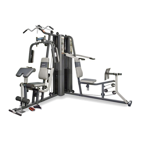
MARCY CORNER GYM
IMPEX FITNESS PRODUCTS
14777 DON JULIAN RD., CITY OF INDUSTRY, CA 91746
Tel: (800) 999-8899 Fax: (626) 961-9966
www.impex-fitness.com
info@impex-fitness.com
CR 4
Advertisement
Table of Contents

Related Manuals for Impex MARCY MWB CR 4


Summary of Contents for Impex MARCY MWB CR 4
- Page 1 Safety Notice Hardware Identifier Assembly Instruction Parts List Resistance Chart How to Use Warranty Ordering Parts Model MWB CR 4 Retain This Manual for Reference 6-18-01 OWNER'S MANUAL MARCY CORNER GYM CR 4 IMPEX FITNESS PRODUCTS 14777 DON JULIAN RD., CITY OF INDUSTRY, CA 91746 Tel: (800) 999-8899 Fax: (626) 961-9966 www.impex-fitness.com...
-
Page 2: Table Of Contents
ORDERING PARTS... BEFORE YOU BEGIN Thank you for selecting the MARCY CR4 PERSONAL TRAINER by IMPEX FITNESS PRODUCTS. For your safety and benefit, read this manual carefully before using the machine. As a manufacturer, we are committed to provide you complete customer satisfaction. -
Page 3: Important Safety Notices
THIS IS ESPECIALLY IMPORTANT FOR INDIVIDUALS OVER THE AGE OF 35 OR PERSONS WITH PRE-EXISTING HEALTH PROBLEMS. READ ALL INSTRUCTIONS BEFORE USING ANY FITNESS EQUIPMENT. IMPEX INC. ASSUMES NO RESPONSIBILITY FOR PERSONAL INJURY OR PROPERTY DAMAGE SUSTAINED BY OR THROUGH THE USE OF THIS PRODUCT. -
Page 5: Assembly Instructions
Tools Required to Assemble the Machine: Two Adjustable Wrenches and Allen Wrenches NOTE: It is strongly recommended this machine be assembled by two or more people to avoid possible injury. STEP 1 (See Diagram 1) A.) Place the Right Base Frame (#1) and Left Base Frame (#2) on the floor, at a right angle to each other. - Page 6 STEP 2 (See Diagram 2) A.) Attach the Right Upper Frame (#6) to the top of the Right Vertical Beam (#3). Secure it with two M10 x 2 ¾” Carriage Bolts (#90), one 4 ¾” x 2” Bracket (#38), two M10 Aircraft Nuts (#110).
- Page 8 STEP 3 (See Diagram 3) A.) Attach the Seat Support Frame (#14) to the Right Vertical Beam (#3). Secure it with two M10 x 2 ¾” Carriage Bolts (#90), one 4 ¾” x 2” Bracket (#38), two Nuts (#110). B.) Attach two Vertical Supports (#16) to the front of the Seat Support (#14). Secure them with two M10 x 2 ¾”...
- Page 9 STEP 4 (See Diagram 4) A.) Attach four 1” x ½” Bushings (#55) to the Leg Press Pivot Arm (#18). Attach the Pivot Arm to the bracket on the Right Base Frame (#1). Secure it with one M12 x 3 1/8” Hex Head Bolt (#91), two 1”...
- Page 10 STEP 5 (See Diagram 5) A.) Insert the Chromed Adjustment Tube (#20) into the Leg Press Frame (#19). Secure it with a Quick Release Pin (#62). B.) Attach the Foot Plate (#21) to the Chromed Tube (#20) and secure it with a L-Shaped Pin (#112). C.) Attach the Bench Press Frame (#11) to the pivot tube on the Right Base Frame (#1).
- Page 11 STEP 6 (See Diagram 6) A.) Attach the Butterfly Support Frame (#8) to the front of the Right Vertical Beam (#3). Attach the Butterfly Pulley Support (#113) to the back of the Right Vertical Beam (#3). Secure them with two M10 x 3”...
- Page 12 STEP 7 (See Diagram 7) A.) Attach the Leg Developer Frame (#15) to the Left Vertical Beam (#4). Secure it with two M10 x 2 ¾” Carriage Bolts (#90), one 4 ¾” x 2” Bracket (#38), two Aircraft Nuts (#110). B.) Attach the Leg Developer Frame (#15) to the Left Base Frame (#2).
- Page 13 STEP 8 (See Diagram 8) A.) Attach the Seat (#40) to the Leg Developer Frame (#15). Secure it with two (#107) and M8 x 2 ½” Allen Bolts (#101). B.) Attach both Left Handlebar (#32) and Right Handlebar (#33) to the Leg Developer Frame (#15) underneath the Seat (#40).
- Page 14 STEP 9 (See Diagram 9 & 15) A.) Attach a Pulley (#58) to the bracket on the Right Butterfly Arm (#10). Secure it with one M10 x 1 ¾” Allen Bolt (#98), two ¾” Washers (#106), and one M10 Aircraft Nut (#110). Repeat to install another Pulley to the other side.
- Page 15 STEP 10 (See Diagram 10 & 15) A.) Attach the Ball-end of the 132” Upper Cable (#85) to the Right Upper Frame (#6). Install a Pulley (#58). Push two Bushings (#56) into the holes from both sides. Secure it with one M10 x 2 ½” Allen Bolt (#97) and M10 Aircraft Nut (#110).
- Page 16 STEP 11 (See Diagram 11 & 15) A.) Attach one end of the 327 ½” Leg Press Cable (#83) to the bracket on the Leg Press Pivot Arm (#18). (See C View) Secure it with one M10 x 1” Allen Bolt (#99), two one M10 Aircraft Nut (#110).
- Page 18 STEP 12 (See Diagram 12 & 15) A.) Attach the Ball-end of the 158” Ab Cable (#86) to the opening on the Left Vertical Beam (#4). Install a Pulley (#58). Push two Bushings (#56) from both sides of the Beam. Secure it with a M10 x 2 ½”...
- Page 19 STEP 13 (See Diagram 13 & 15) A.) Attach the Ball-end of the 102” Leg Curl Cable (#87) to the opening on the Leg Developer (#23). Install a Pulley (#58) to the opening. Attach two Bushings (#56) to the holes on the Leg Developer.
- Page 20 STEP 14 (See Diagram 14 & 15) A.) Tighten all the nuts and bolts previously installed. B.) Before putting the Weight Plates on, now move the machine to the corner of the room or place where you will use the machine. C.) Lift up the Selector Rod and install the Weight Plates.
-
Page 22: Parts List
PARTS LIST KEY NO. DESCRIPTION Right Base Frame Left Base Frame Right Vertical Beam Left Vertical Beam Rear Vertical Beam Right Upper Frame Left Upper Frame Butterfly Support Frame Left Butterfly Right Butterfly Bench Press Frame Bench Press Handle Vertical Press Frame Seat Support Frame Leg Developer Frame Vertical Support... -
Page 24: How To Use
HOW TO USE How to use the quick release connector. Insert The Clip is removed from the Connector. Connector Clip Place the chain in between the connector and insert the Clip through the holes. Chain Push down the Clip to secure. -
Page 25: Warranty
No other warranty beyond that specifically set forth above is authorized by IMPEX. IMPEX is not responsible or liable for indirect, special or consequential damages arising out of or in connection with the use or performance of the product or other damages with respect to any economic loss, loss of property, loss of revenues or profits, loss of enjoyments or use, costs of removal, installation or other consequential damages or whatsoever natures.
Need help?
Do you have a question about the MARCY MWB CR 4 and is the answer not in the manual?
Questions and answers