Table of Contents
Advertisement
Quick Links
Contents
A-Z
1
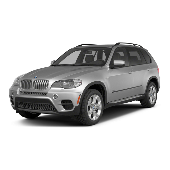
Vehicle height: 69.4 inches/1,762 mm
2
Vehicle width without exterior mirrors:
76.3 inches/1,938 mm
THE BMW X5.
OWNER'S MANUAL.
Online Edition for Part no. 01 40 2 910 949 - VII/13
Owner's Manual for
Vehicle
3
Vehicle width with exterior mirrors: 86.0 in‐
ches/2,184 mm
The Ultimate Driving
Machine
Advertisement
Table of Contents

Related Manuals for BMW X5 2013


Summary of Contents for BMW X5 2013
- Page 1 Machine Vehicle height: 69.4 inches/1,762 mm Vehicle width with exterior mirrors: 86.0 in‐ ches/2,184 mm Vehicle width without exterior mirrors: 76.3 inches/1,938 mm THE BMW X5. OWNER'S MANUAL. Online Edition for Part no. 01 40 2 910 949 - VII/13...
- Page 3 The more familiar you are with your vehicle, the better control you will have on the road. We therefore strongly suggest: Read this Owner's Manual before starting off in your new BMW. Also use the Integrated Owner's Manual in your vehicle. It con‐...
- Page 4 © 2013 Bayerische Motoren Werke Aktiengesellschaft Munich, Germany Reprinting, including excerpts, only with the written consent of BMW AG, Munich. US English VII/13, 07 13 490 Printed on environmentally friendly paper, bleached without chlorine, suitable for recycling. Online Edition for Part no. 01 40 2 910 949 - VII/13...
-
Page 5: Table Of Contents
Contents Mobility The fastest way to find information on a partic‐ ular topic or item is by using the index, refer to Refueling page 246. Fuel Wheels and tires Engine compartment Notes Engine oil Coolant At a glance Maintenance Cockpit Replacing components iDrive Breakdown assistance... -
Page 6: Notes
For options and equipment not described in Information on BMW, e.g., on technology, is this Owner's Manual, please refer to the Sup‐ available on the Internet: bmwusa.com. plementary Owner's Manuals. -
Page 7: For Your Own Safety
BMW. BMW cannot water. test every product made by other manufactur‐ ers to verify if it can be used on a BMW safely Service and warranty and without risk to either the vehicle, its opera‐ We recommend that you read this publication tion, or its occupants. - Page 8 — possibly with the assistance ous damage to the vehicle. Such damage is of an expert. not covered by the BMW New Vehicle Limited Additional functions that are contractually Warranty. agreed with the customer, such as vehicle lo‐...
-
Page 9: Reporting Safety Defects
National Highway Traffic Safety Adminis‐ a road obstacle, data that will assist in under‐ tration NHTSA, in addition to notifying BMW of standing how a vehicle’s systems performed. North America, LLC, P.O. Box 1227, West‐... - Page 10 Online Edition for Part no. 01 40 2 910 949 - VII/13...
-
Page 11: At A Glance
At a glance These overviews of buttons, switches and displays are intended to familiarize you with your vehicle. You will also become quickly acquainted with the available control concepts and options. Online Edition for Part no. 01 40 2 910 949 - VII/13... -
Page 12: Cockpit
At a glance Cockpit Cockpit Vehicle equipment ment is also described that is not available in a vehicle, e. g., because of the selected optional All standard, country-specific and optional equipment or country variant. This also applies equipment that is offered in the model series is for safety-related functions and systems. - Page 13 Cockpit At a glance Instrument lighting 98 Entertainment source Night Vision, switch on/switch off Volume heat image 117 Voice activation 24 Steering column stalk, left Turn signal 73 Telephone, see user's manual for Navigation, Entertainment and High beams, head‐ Communication lamp flasher 73 Thumbwheel for selection lists 91 High-beam Assistant 97...
-
Page 14: All Around The Center Console
At a glance Cockpit 18 Unlock hood 215 All around the center console All around the headliner 15 Auto Hold 71 Control Display 16 Glove compartment 179 PDC Park Distance Control 145 Ventilation 164 Rearview camera 148 Hazard warning system 230 View 151 Parking assistant 155 Intelligent Safety button 108 Panorama View 153 Automatic climate control 161 HDC Hill Descent... - Page 15 Cockpit At a glance 14 Transmission selector lever 76 All around the headliner Intelligent Emergency Re‐ Reading lamps 99 quest 230 Panoramic glass sunroof 47 Interior lamps 99 Indicator lamp, front passenger Glasses compartment 182 airbag 102 Online Edition for Part no. 01 40 2 910 949 - VII/13...
-
Page 16: Idrive
At a glance iDrive iDrive Vehicle equipment Control Display All standard, country-specific and optional Hints equipment that is offered in the model series is ▷ To clean the Control Display, follow the described in this chapter. Therefore, equip‐ care instructions. ment is also described that is not available in a ▷... - Page 17 iDrive At a glance Press. Turn. Move in four directions. Press. Move in two directions. Buttons on controller Press the but‐ Function MENU Open the main menu. RADIO Opens the Radio menu. MEDIA Opens the CD/Multimedia menu. Opens the Navigation menu. Buttons on controller Opens the Telephone menu.
- Page 18 At a glance iDrive Menu items in the Owner's Manual Press the but‐ Function In the Owner's Manual, menu items that can be selected are set in quotation marks, e.g., BACK Open previous panel. "Settings". OPTION Opens the Options menu. Changing between panels After a menu item is selected, e.g., "Radio", a new panel is displayed.
-
Page 19: Options Menu
iDrive At a glance The function is deactivated. Touchpad Some iDrive functions can be operated using the touchpad on the controller: Selecting functions "Settings" Additional options: move the controller to the "Touchpad" right repeatedly until the "Options" menu is displayed. Select the desired function. - Page 20 At a glance iDrive Turn the controller until "Time/Date" is Function Controls highlighted, and then press the controller. Interactive map. Slide in the correspond‐ ing direction. Enlarge/shrink in‐ Drag the display inwards teractive map. or outwards with the fin‐ gers. Display menu.
-
Page 21: General Information
iDrive At a glance Radio symbols Additional symbols Symbol Meaning Symbol Meaning Satellite radio is switched on. Spoken instructions are switched off. Telephone symbols Split screen Symbol Meaning Incoming or outgoing call. General information Missed call. Additional information can be displayed on the right side of the split screen, e.g., information Wireless network reception from the computer. - Page 22 At a glance iDrive Programmable memory Deleting the button assignments buttons Press buttons 1 and 8 simultaneously for approx. five seconds. General information "OK" The iDrive functions can be stored on the pro‐ grammable memory buttons and called up di‐ Entering letters and numbers rectly, e.g., radio stations, navigation destina‐...
- Page 23 iDrive At a glance Entry comparison Entry of names and addresses: the selection is narrowed down every time a letter is entered and letters may be added automatically. The entries are continuously compared to the data stored in the vehicle. ▷...
-
Page 24: Voice Activation System
At a glance Voice activation system Voice activation system Vehicle equipment Using voice activation All standard, country-specific and optional Activating the voice activation system equipment that is offered in the model series is described in this chapter. Therefore, equip‐ Press the button on the steering ment is also described that is not available in a wheel. -
Page 25: Adjusting The Volume
Voice activation system At a glance Executing functions using short Via short command commands Playback of the CD can also be started via a Functions on the main menu can be performed short command. directly by means of short commands, nearly Switch on the Entertainment sound output irrespective of which menu item is currently if necessary. - Page 26 At a glance Voice activation system Notes on Emergency Requests Do not use the voice activation system to ini‐ tiate an Emergency Request. In stressful situa‐ tions, the voice and vocal pitch can change. This can unnecessarily delay the establish‐ ment of a telephone connection.
-
Page 27: Integrated Owner's Manual In The Vehicle
Integrated Owner's Manual in the vehicle At a glance Integrated Owner's Manual in the vehicle Vehicle equipment Select components All standard, country-specific and optional Press the button. equipment that is offered in the model series is Turn the controller: open "Vehicle Info". described in this chapter. - Page 28 At a glance Integrated Owner's Manual in the vehicle Context help - Owner's Manual to the Programmable memory buttons temporarily selected function General information The relevant information can be opened di‐ rectly. The Owner's Manual can be stored on the pro‐ grammable memory buttons and called up di‐...
- Page 29 Integrated Owner's Manual in the vehicle At a glance Online Edition for Part no. 01 40 2 910 949 - VII/13...
- Page 30 Online Edition for Part no. 01 40 2 910 949 - VII/13...
-
Page 31: Controls
Controls This chapter is intended to provide you with information that will give you complete control of your vehicle. All features and accessories that are useful for driving and your safety, comfort and convenience are described here. Online Edition for Part no. 01 40 2 910 949 - VII/13... -
Page 32: Opening And Closing
Controls Opening and closing Opening and closing Vehicle equipment Integrated key All standard, country-specific and optional equipment that is offered in the model series is described in this chapter. Therefore, equip‐ ment is also described that is not available in a vehicle, e. -
Page 33: Profile Management
▷ The USB interface in the center armrest onto a USB device. Starting the engine with emergency ▷ BMW Online. detection of the remote control Profile management Opening the profiles A different profile can be called up than the one associated with the remote control cur‐... - Page 34 Open "Options". "Settings" "Display user list at startup" "Profiles" "Import profile" Personal Profile settings BMW Online: "BMW Online" The following functions and settings can be USB interface, refer to page 175: "USB stored in a profile. device" ▷ Collision warning: warning time.
-
Page 35: Central Locking System
Opening and closing Controls ▷ Tone: tone settings. The following takes place simultaneously when locking/unlocking the vehicle via the re‐ ▷ Automatic climate control: settings. mote control: ▷ Steering wheel position. ▷ Depending on how the vehicle is equipped, ▷ Navigation: map views, route criteria, voice the theft protection is activated/deacti‐... -
Page 36: Courtesy Lamps
Controls Opening and closing Opening and closing: from Switching on interior lamps and courtesy lamps the outside Press the button on the remote control Using the remote control with the vehicle locked. General information Panic mode Take the remote control with you You can trigger the alarm system if you find People or animals left unattended in a yourself in a dangerous situation. - Page 37 Opening and closing Controls Using the door lock Provide edge protection Sharp or angular objects can hit the rear General information window while driving and damage the heating wires of the rear window. Provide edge protec‐ Locking from the outside tion.◀...
-
Page 38: Manual Operation
Controls Opening and closing Doors Manual operation If an electrical malfunction occurs, lock or un‐ Automatic Soft Closing lock the vehicle using the integrated key via the door lock on the driver's door. To close the doors, push lightly. It is closed automatically. Integrated key in opening, arrow, press and remove cover. -
Page 39: Opening From The Inside
Opening and closing Controls Opening from the inside Manual opening When there is an electrical defect. Press the button. Fold the rear seat backrest forward. The tailgate is opened if the vehicle is station‐ In the lower tailgate, loosen and remove ary, provided that the tailgate has not been the cover using the onboard tool kit or a locked. -
Page 40: Locking The Vehicle
Controls Opening and closing Do not place the remote control in the Note the opening height of the tailgate cargo area The tailgate pivots back and up when it Take the remote control with you and do not opens. Ensure that there is sufficient clearance leave it in the cargo area;... - Page 41 Opening and closing Controls Provide edge protection Sharp or angular objects can hit the rear window while driving and damage the heating wires of the rear window. Provide edge protec‐ tion.◀ Closing The floor panel in the cargo area must be folded down;...
-
Page 42: The Concept
Controls Opening and closing Lower tailgate ▷ The next unlocking and locking cycle is not possible until after approx. 2 seconds. Opening ▷ The engine can only be started if the re‐ mote control is inside the vehicle. Comparison with ordinary remote control The functions can be controlled by pressing the buttons of the remote control or Comfort... -
Page 43: Automatic Locking
Opening and closing Controls sumers are switched off before locking the ve‐ Select symbol or "Unlock button:" hicle. Select the desired function: ▷ "Driver's door only" Convenient closing Only the driver's door and the fuel filler Press the area on the door handle, arrow 2, flap are unlocked. -
Page 44: Alarm System
Controls Opening and closing When the vehicle is unlocked, these positions cess at the door lock, the alarm system is are automatically retrieved if this function was armed or disarmed at the same time. activated. Door lock and armed alarm system Pinch hazard when moving back the seat The alarm system is triggered when the door is If this function is used, first make sure... -
Page 45: Power Windows
Opening and closing Controls Indicator lamp on the interior rearview Avoiding unintentional alarms mirror The tilt alarm sensor and interior motion sen‐ sor can be switched off together, such as in the following situations: ▷ In automatic car washes. ▷ In duplex garages. - Page 46 Controls Opening and closing Opening wise, the closing action may not stop in certain situations, e.g., if thin objects are present.◀ ▷ Press the switch to the resistance No window accessories point. Do not install any accessories in the The window opens while the switch is held. range of movement of the windows;...
-
Page 47: Roller Sunblinds
Opening and closing Controls Safety switch for rear operation Press the safety switch when transport‐ ing children in the rear; otherwise, injury may result if the windows are closed without super‐ vision.◀ Roller sunblinds Roller sunblinds for the rear side Tilting the glass sunroof windows Push switch upward briefly. - Page 48 Controls Opening and closing Opening/closing the glass sunroof and Pinch protection is limited and the roof re‐ sliding visor together opens slightly if the closing force exceeds a certain value. Briefly press the switch twice in Press the switch forward again beyond the succession in the desired direc‐...
-
Page 49: Adjusting
Adjusting Controls Adjusting Vehicle equipment Semi-electrically adjustable seats All standard, country-specific and optional At a glance equipment that is offered in the model series is described in this chapter. Therefore, equip‐ ment is also described that is not available in a vehicle, e. - Page 50 Controls Adjusting Forward/backward Electrically adjustable seats At a glance Pull the lever and slide the seat in the desired direction. Seat, mirror, and steering wheel memory After releasing the control, move the seat for‐ ward or back slightly to make sure it engages Shoulder support properly.
-
Page 51: Lumbar Support
Adjusting Controls Thigh support Height Multifunctional seat Seat tilt Adjust the position using the lever. Sport seat Backrest tilt Pull the lever at the front of the seat and adjust the thigh support. Lumbar support The curvature of the seat backrest can be ad‐ justed in such a way that it supports the lumbar region of the spine. -
Page 52: Switching Off
Controls Adjusting Backrest width Switching off Change the width of the back‐ Press the button longer. rest using the side wings to ad‐ The LEDs go out. just the lateral support. Temperature distribution The heating action in the seat cushion and Shoulder support backrest can be distributed in different ways. -
Page 53: Rear Seats
Adjusting Controls The LEDs go out. Rear seats Second row of seats Hints Center armrest Pull the lever, and apply your weight to the When folding down the center armrest, backrest or lift it off, as necessary. ensure that the area below the center head re‐ straint is clear. -
Page 54: Safety Belts
Controls Adjusting Rear seat heating Before folding up the backrest, remove the cargo cover, refer to page 176. If necessary, slide the second row of seats forward a little. Pull the lever, arrow, to unlock the back‐ rest. Switching on Press the button once for each tem‐... - Page 55 Adjusting Controls Hints Buckling the belt Always make sure that safety belts are being worn by all occupants before driving away. Although airbags enhance safety by providing added protection, they are not a substitute for safety belts. ▷ The shoulder strap's anchorage point will be correct for adult seat occupants of ev‐...
-
Page 56: Active Head Restraint
Do not hang objects, e.g., clothes hangers, on the head restraints. Distance to back of head: manual head ▷ Only attach accessories approved by BMW restraints to the seat or head restraint. Otherwise, the protective function of the active head restraint will be impaired and the per‐... -
Page 57: Adjusting The Height
Adjusting Controls Distance to back of head: electrical Adjusting the height head restraints The head restraint is automatically reposi‐ tioned when the shoulder support is adjusted. Adjusting the side extensions ▷ To raise: pull. ▷ To lower: press the button, arrow 1, and push the head restraint down. -
Page 58: Safety Mode
Controls Adjusting Seat, mirror, and steering The corresponding seat position is performed automatically. wheel memory The procedure stops when a switch for adjust‐ ing the seat or one of the buttons is pressed. General information Safety mode Close the driver's door or switch on the ig‐ nition. -
Page 59: Automatic Dimming Feature
Adjusting Controls General information Engage transmission position R. The mirror on the passenger side is more Deactivating curved than the driver's side mirror. Slide the mirror changeover switch to the pas‐ Estimating distances correctly senger's side mirror position. Objects reflected in the mirror are closer than they appear. -
Page 60: Steering Wheel
Controls Adjusting Interior rearview mirror, automatic Manual steering wheel adjustment dimming feature The concept Fold the lever down. Move the steering wheel to the preferred height and angle to suit your seating posi‐ Photocells are used for control: tion. ▷ In the mirror glass. - Page 61 Adjusting Controls Switching on/off Press the button. ▷ On: the LED lights up. ▷ Off: the LED goes out. Online Edition for Part no. 01 40 2 910 949 - VII/13...
-
Page 62: Transporting Children Safely
Controls Transporting children safely Transporting children safely Vehicle equipment vated. Automatic deactivation of front passen‐ ger side airbags, refer to page 102. All standard, country-specific and optional equipment that is offered in the model series is Note described in this chapter. Therefore, equip‐ Deactivated front passenger airbags ment is also described that is not available in a If a child restraint fixing system is used in... -
Page 63: Deactivating Airbags
Transporting children safely Controls Lock the rear seat backrests in position position to obtain the best possible position for the belt and to offer optimal protection in the Before installing a child restraint system, event of an accident. make sure that the rear seat backrests are locked;... -
Page 64: Latch Child Restraint Fixing
Controls Transporting children safely Unlocking the safety belt Position Unbuckle the belt buckle. Remove the child restraint fixing system. Allow the belt webbing to be pulled in com‐ pletely. LATCH child restraint fixing system LATCH: Lower Anchors and Tether for CHil‐ Mounts for the lower LATCH anchors are lo‐... -
Page 65: Rear Doors
Transporting children safely Controls Note Tighten the retaining strap by pulling it down. Mounting eyes Lower and lock head restraints as needed. Only use the mounting eyes for the up‐ per retaining strap to secure child restraint fix‐ ing systems; otherwise, the mounting eyes Locking the doors and could be damaged.◀... -
Page 66: Driving
Controls Driving Driving Vehicle equipment Note If the engine is switched off and the ignition is All standard, country-specific and optional switched on, the system automatically equipment that is offered in the model series is switches to the radio ready state when the described in this chapter. -
Page 67: Automatic Transmission
Driving Controls Radio ready state Do not wait for the engine to warm-up while the vehicle remains stationary. Start driving at Activate radio ready state: moderate engine speeds. ▷ When the engine is running: press the Start/Stop button. Automatic transmission Some electronic systems/power consumers remain ready for operation. -
Page 68: Automatic Mode
Controls Driving The radio ready state is switched on. The display indicates that the conditions for an automatic en‐ Set the parking brake. gine stop have not been satis‐ fied. Automatic Engine Start/Stop Function Note The engine is not switched off automatically in The concept the following situations: The Auto Start/Stop function helps save fuel. - Page 69 Driving Controls Safety mode Preventing an engine stop using the brake pedal After the engine switches off automatically, it will not start again automatically if any one of The engine stop can be actively prevented the following conditions are met. within one second after the vehicle comes to a standstill.
-
Page 70: Automatic Deactivation
Controls Driving Transmission position P is engaged auto‐ Set the parking brake and further secure matically. the vehicle as required Set the parking brake. Set the parking brake firmly when parking; oth‐ erwise, the vehicle could roll. On steep upward Engine start as usual via Start/Stop button. -
Page 71: For Your Safety
Driving Controls Inadvertent operation of the accelerator Leaving the vehicle with the engine run‐ pedal ning Make sure that the accelerator pedal is not op‐ Before leaving the vehicle with the engine run‐ erated unintentionally; otherwise, the vehicle is ning, engage position P of the automatic trans‐ set in motion and there is a risk of an acci‐... -
Page 72: Manual Release
Controls Driving Before driving into a car wash Secure the vehicle in a manner appropriate to the inclination of the road, e.g., with a wheel Before driving into the car wash, deacti‐ chock; otherwise, there is the danger of the ve‐ vate Automatic Hold;... -
Page 73: Headlamp Flasher
Driving Controls Using turn signals power. Otherwise, it cannot be ensured that the parking brake will function properly.◀ Putting the parking brake into operation Switch on the ignition. Press the switch while the brake is depressed or transmission position P is engaged. -
Page 74: Rain Sensor
Controls Driving Washer/wiper system Switching off and brief wipe Switching the wipers on/off and brief wipe Do not switch on the wipers if frozen Do not switch on the wipers if they are frozen onto the windshield; otherwise, the wiper blades and the windshield wiper motor may be damaged.◀... -
Page 75: Rear Window Wiper
Driving Controls Deactivate the rain sensor in car washes Avoid using the washer when the reservoir is empty; otherwise, you could damage the Deactivate the rain sensor when passing pump.◀ through an automatic car wash; otherwise, damage could be caused by undesired wiper Windshield washer nozzles activation.◀... -
Page 76: Washer Fluid
Follow the usage instructions on the washer fluid con‐ Transmission positions tainer. Use BMW’s Windshield Washer Con‐ centrate or the equivalent.◀ D Drive, automatic position Position for normal vehicle operation. All for‐... -
Page 77: Engaging The Transmission Position
Driving Controls N is Neutral Depress the brake until you start driving Use in automatic car washes, for example. The vehicle can roll. To prevent the vehicle from creeping after you select a driving position, maintain When the ignition is switched off, refer to pressure on the brake pedal until you are page 66, position P is engaged automatically. - Page 78 Controls Driving Engaging P Once maximum engine speed is attained, M/S manual mode is automatically upshifted as needed. Switching to manual mode ▷ To shift down: press the selector lever for‐ ward. ▷ To shift up: pull the selector lever rear‐ wards.
- Page 79 Driving Controls Shift paddles Hints Component wear Do not use Launch Control too often; otherwise, this may result in premature wear of components due to the high stress placed on the vehicle.◀ Did not use Launch Control during the break- in, refer to page 188, period.
-
Page 80: Displays
Controls Displays Displays Vehicle equipment ment is also described that is not available in a vehicle, e. g., because of the selected optional All standard, country-specific and optional equipment or country variant. This also applies equipment that is offered in the model series is for safety-related functions and systems. - Page 81 Displays Controls Overview, instrument cluster with enhanced features Fuel gauge 86 Engine oil temperature 86 Speedometer Electronic displays 82 Indicator/warning lamps 84 Display/reset miles 87 Tachometer 86 Online Edition for Part no. 01 40 2 910 949 - VII/13...
- Page 82 Controls Displays Electronic displays Overview, instrument cluster Clock 87 Computer 91 External temperature 87 Service requirements 88 Messages, e.g., Check Control 84 Kilometer display 87 Transmission displays 79 Selection list, e.g., radio 91 Selection list, e.g., Driving Dynamics Con‐ trol 131 Online Edition for Part no. 01 40 2 910 949 - VII/13...
- Page 83 Displays Controls Overview, instrument cluster with navigation system or TV Kilometer display 87 Symbol for service need External temperature 87 Transmission display 79 Time 87 Current fuel consumption 88 Selection list, e.g., radio 91 Energy recovery 88 Navigation display, see user's manual for Service requirements 88 Navigation, Entertainment and Communi‐ Messages, e.g., Check Control 84 cation.
-
Page 84: Check Control
Controls Displays Overview, instrument cluster with enhanced features Messages, e.g. Check Control 84 Kilometer display 87 Time 87 Selection list, e.g., radio 91 Range 87 Current fuel consumption 88 Computer 91 Energy recovery 88 Navigation display, see user's manual for External temperature 87 Navigation, Entertainment and Communi‐ Transmission display 79 cation. -
Page 85: Text Messages
Displays Controls Overview: indicator/warning lamps Symbol Function or system Safety belts. Symbol Function or system Turn signal. Airbag system. Parking brake. Steering system. Parking brake in Canadian models. Engine functions. Automatic hold. Engine functions in Canadian mod‐ els. Front fog lamps. Brake system. -
Page 86: Fuel Gauge
Controls Displays Symbols "Check Control" Depending on the Check Control message, the Select the text message. following functions can be selected. Messages after trip completion ▷ "Owner's Manual" Special messages that are displayed during Display additional information about the driving are displayed again after the ignition is Check Control message in the Integrated switched off. -
Page 87: Coolant Temperature
Displays Controls Coolant temperature Time If the coolant along with the engine becomes The time is displayed at the bot‐ too hot, a Check Control message is displayed. tom of the instrument cluster. Check the coolant level, refer to page 219. Setting the time and time for‐... -
Page 88: Current Fuel Consumption
Controls Displays Current fuel consumption Detailed information on service requirements Displays the current fuel con‐ More information on the scope of service re‐ sumption. You can check quired can be displayed on the Control Dis‐ whether you are currently driv‐ play. -
Page 89: Gear Shift Indicator
Displays Controls Gear shift indicator Automatic Service Request Data regarding the service status or legally The concept mandated inspections of the vehicle are auto‐ matically transmitted to your service center The system recommends the most fuel effi‐ before a service due date. cient gear in the current driving situation. - Page 90 Controls Displays No Passing Information "Info display" No Passing Information in the instrument clus‐ "Speed limit information" ter displays the beginnings and ends of no If speed limit detection is switched on, it can passing zones detected by the camera. The be displayed on the info display in the instru‐...
-
Page 91: Instrument Cluster
Displays Controls Activating a list and creating the ▷ When driving very close to the vehicle in setting front of you. ▷ When driving toward bright lights. ▷ When the windshield behind the interior rearview mirror is fogged over, dirty or cov‐ ered by a sticker, etc. -
Page 92: Information At A Glance
Controls Displays Information at a glance Average fuel consumption Repeatedly pressing the button on the turn The average fuel consumption is calculated for signal lever calls up the following information the period during which the engine is running. on the info display: The average fuel consumption is calculated for ▷... -
Page 93: Trip Computer
Displays Controls The warning is repeated if the vehicle speed "Automatically reset": all values are reset drops below the set speed limit once by at approx. 4 hours after the vehicle comes to least 3 mph/5 km/h. a standstill. Displaying, setting or changing the Display on the Control Display limit Display the onboard computer or trip computer... - Page 94 Controls Displays Setting the voice dialog The time is stored. Voice dialog for the voice activation system, Setting the time format refer to page 25. "Settings" Units of measure "Time/Date" "Format:" Setting the units of measure Select the desired format. To set the units for fuel consumption, route/ The time format is stored.
-
Page 95: Lamps
Lamps Controls Lamps Vehicle equipment If the driver door is opened with the ignition switched off, the exterior lighting is automati‐ All standard, country-specific and optional cally switched off at these switch settings. equipment that is offered in the model series is described in this chapter. -
Page 96: Roadside Parking Lamps
Controls Lamps Roadside parking lamps "Pathway lighting:" Set the duration. The setting is stored for the remote control currently in use. Automatic headlamp control Switch position : the low beams are switched on and off automatically, e.g., in tun‐ nels, in twilight or if there is precipitation. The indicator lamp in the instrument cluster lights The vehicle can be illuminated on one side. - Page 97 Lamps Controls To avoid blinding oncoming traffic, the Adap‐ The High-beam Assistant can be activated tive Light Control does not swivel to the driv‐ when the low beams are switched on. er's side when the vehicle is at a standstill. Turn the light switch to When driving in reverse, only the turning lamp Press the button on the turn signal lever,...
-
Page 98: Fog Lamps
Controls Lamps Fog lamps System limits Personal responsibility Front fog lamps The high-beam assistant cannot serve as The parking lamps or low beams must be a substitute for the driver's personal judgment switched on. of when to use the high beams. Therefore, manually switch off the high beams in situa‐... -
Page 99: Reading Lamps
Lamps Controls To deactivate the ambient light: "Off". Setting the brightness The brightness of the ambient light can be ad‐ justed via the thumbwheel for the instrument lighting but also independently of it. "Settings" "Lighting" Interior lamps "Brightness:" Reading lamp Adjust the brightness. -
Page 100: Safety
Controls Safety Safety Vehicle equipment ment is also described that is not available in a vehicle, e. g., because of the selected optional All standard, country-specific and optional equipment or country variant. This also applies equipment that is offered in the model series is for safety-related functions and systems. - Page 101 Safety Controls Protective action ▷ Never modify either the individual compo‐ nents or the wiring in the airbag system. Airbags are not triggered in every impact situa‐ This also applies to steering wheel covers, tion, e.g., in less severe accidents or rear-end the dashboard, the seats, the roof pillars collisions.
-
Page 102: Deactivation System
Controls Safety When there is a malfunction, have the ▷ Do not attach covers, cushions, ball mats airbag system checked immediately or other items to the front passenger seat unless they are specifically recommended When there is a malfunction, have the airbag by the manufacturer of your vehicle. -
Page 103: Tire Pressure Monitor Tpm
Safety Controls Tire Pressure Monitor TPM Detected child seats The system generally detects children seated The concept in a child seat, especially in the child seats that were required by NHTSA when the vehicle was The system monitors tire pressure in the four manufactured. -
Page 104: Additional Information
Controls Safety All wheels green After driving faster than 19 mph/30 km/h for a short period, the tire inflation pressures set are System is active and will issue a warning rela‐ accepted as reference values. The reset is tive to the tire inflation pressures stored during completed automatically during driving. - Page 105 Safety Controls Actions in the event of a flat tire For a vehicle containing an average load, the possible driving distance is approx. Normal tires 50 miles/80 km. Identify the damaged tire. When the vehicle is driven with a damaged tire, its handling characteristics change, e.g., re‐...
- Page 106 Controls Safety System limits proper tire inflation pressure for those tires.) As an added safety feature, your vehicle has The system does not function properly if a re‐ been equipped with a tire pressure monitoring set has not been carried out, e.g., a flat tire is system (TPMS) that illuminates a low tire pres‐...
- Page 107 Safety Controls FTM Flat Tire Monitor Start the initialization with "Perform reset". Drive away. The concept The initialization is completed while driving, The system does not measure the actual infla‐ which can be interrupted at any time. tion pressure in the tires. The initialization automatically continues when It detects a pressure loss in a tire by comparing driving resumes.
- Page 108 Controls Safety ▷ When driving on a snowy or slippery road For a vehicle containing an average load, the surface. possible driving distance is approx. 50 miles/80 km. ▷ Sporty driving style: slip in the drive wheels, high lateral acceleration. When the vehicle is driven with a damaged tire, its handling characteristics change, e.g., re‐...
-
Page 109: Collision Warning
Safety Controls ▷ Lane departure warning, refer to ▷ Intelligent Safety systems are individually page 120. switched off according to individual set‐ ting. ▷ Active Blind Spot Detection, refer to page ▷ LED lights up orange or goes out depend‐ ing on the individual setting. - Page 110 Controls Safety The collision warning is available even if cruise Intelligent Safety button control has been deactivated. When the vehicle is intentionally brought close Switching on/off to a vehicle, the collision warning is delayed to Some Intelligent Safety systems are automati‐ avoid false warnings.
-
Page 111: Functional Limitations
Safety Controls If the vehicle is equipped with Night Vision with The braking intervention is executed only if Dynamic Light Spot: DSC Dynamic Stability Control is switched on and Dynamic Traction Control DTC is acti‐ "Settings" vated. "Intelligent Safety" The braking intervention can be interrupted by "Frontal Coll. -
Page 112: Radar Sensor
Controls Safety Detection range ▷ If the driving stability control systems are limited or deactivated, for example, DSC OFF. ▷ If the camera in the mirror or the radar sen‐ sor is dirty or obscured. ▷ During calibration of the camera immedi‐ ately after vehicle shipment. - Page 113 Safety Controls Camera Setting the warning time The warning time can be set via iDrive. These settings have no effect on the time of the warning when the system prompts the driver to intervene or brake. "Settings" "Frontal Coll. Warning" Activate the desired warning time on the Control Display.
- Page 114 Controls Safety System limits The braking intervention is executed only if DSC Dynamic Stability Control is switched on Be alert and Dynamic Traction Control DTC is acti‐ Due to system limitations, warnings may vated. be not be issued at all, or may be issued late or Above approx.
- Page 115 Safety Controls Prewarning sensitivity Detection range Depending on the set prewarning time, this may result in increased false warnings. Pedestrian warning Depending on how the vehicle is equipped, the function warns of an imminent collision with pedestrians during daytime or nighttime. The function is subdivided into the following The warning area in front of the vehicle is div‐...
- Page 116 Controls Safety Camera Warning with braking function Adapting your speed and driving style The warning does not relieve the driver of the responsibility to adapt his or her driving speed and style to the traffic conditions.◀ Display If a collision with a person detected in this way is imminent, a warning symbol appears on the instrument cluster and in the Head-up Display.
-
Page 117: Functional Limitations
Safety Controls Detection range Heat image The detection capability of the camera is lim‐ ited. This may result in the warning not being is‐ sued or being issued late. For example, the following situations may not be detected: ▷ Partially covered pedestrians. ▷... - Page 118 Controls Safety At a glance In addition, the system also detects animals above a certain minimum size, e.g., deer. Buttons in the vehicle With heat image activated on the Control Dis‐ play: People detected by the system are displayed with a slight yellow hue. Animals detected by the system are displayed in a darker yellow.
- Page 119 Safety Controls Switching on/off ▷ Select the symbol. Turn the controller until the desired setting Switching on automatically is reached, and press the controller. Every time the engine is started using the Display Start/Stop button, the system is automatically active at dark. Warning of people or animals in Switching on/off manually danger...
-
Page 120: Lane Departure Warning
Controls Safety Prewarning ▷ When the camera is dirty or the protective glass is damaged. The yellow symbol is displayed when a ▷ In heavy fog, rain or snowfall. person is detected in the central area, arrow 1, immediately in front of the ve‐ ▷... - Page 121 Safety Controls may vary depending on the current driving sit‐ Keep the windshield in the area behind the in‐ uation. terior rear view mirror clean and clear. The system does not provide a warning if the turn signal is set before leaving the lane. Switching on/off Some Intelligent Safety systems are automati‐...
- Page 122 Controls Safety Active Blind Spot Detection End of warning The warning ends: The concept ▷ Automatically after approx. 3 seconds. ▷ When returning to your own lane. ▷ When braking hard. ▷ When using the turn signal. System limits The system may not be fully functional in the following situations: ▷...
-
Page 123: Radar Sensors
Safety Controls At a glance ▷ LED lights up orange or goes out depend‐ ing on the individual setting. Button in the vehicle Press the button again: ▷ All Intelligent Safety systems are switched ▷ The LED lights up green. Hold the button down: ▷... -
Page 124: Brake Force Display
Controls Safety ▷ In heavy fog, rain or snowfall. ▷ During heavy brake application, the inner brake lamps light up in addition. ▷ In tight curves or on narrow lanes. ▷ If the bumper is dirty or iced up, or covered with stickers. - Page 125 Safety Controls ▷ Personal driving style, for example, steer‐ minimize the risk in the event of an accident as ing behavior. much as possible. ▷ Driving conditions, for example, length of Critical driving situations may include: trip. ▷ Full brake applications. Starting at approximately 43 mph/70 km/h, the ▷...
- Page 126 Controls Safety using the red button in the buckle. Fasten the belt before continuing on your trip. PostCrash In the event of an accident, the system can bring the car to a halt automatically without in‐ tervention by the driver in certain situations. This can reduce the risk of a further collision and the consequences thereof.
-
Page 127: Driving Stability Control Systems
Driving stability control systems Controls Driving stability control systems Vehicle equipment Drive-off assistant All standard, country-specific and optional This system supports driving away on gradi‐ equipment that is offered in the model series is ents. The parking brake is not required. described in this chapter. -
Page 128: Dynamic Performance
Controls Driving stability control systems Dynamic Performance Adjust your driving style to the situation Control An appropriate driving style is always the responsibility of the driver. The Dynamic Performance Control increases The laws of physics cannot be repealed, even both the agility of the vehicle as well as the with DSC. -
Page 129: Hdc Hill Descent Control
Driving stability control systems Controls DTC Dynamic Traction The indicator lamp lights up: DTC Dy‐ namic Traction Control is activated. Control The concept xDrive The DTC system is a version of the DSC in which forward momentum is optimized. xDrive is the all-wheel-drive system of your ve‐ The system ensures maximum forward mo‐... -
Page 130: Active Steering
Controls Driving stability control systems Activating HDC Hill Descent Control can be activated at speeds below approx. 22 mph/35 km/h. When driving downhill, the vehicle reduces its speed to approx. walking speed and then keeps its speed constant. As long as there is active braking, the system is on standby. -
Page 131: Dynamic Drive
Driving stability control systems Controls At higher speeds, the steering angle is increas‐ The programs can be selected via the Driving ingly reduced. Dynamics Control, refer to page 131. This enables even more precise handling at SPORT/SPORT+ high speeds and more responsive steering with reduced steering angle at low speeds. - Page 132 Controls Driving stability control systems Operating the programs TRACTION Maximum traction on loose road surfaces. DTC Press the button Program Dynamic Traction Control is switched on. Driv‐ ing stability is limited during acceleration and DSC OFF when driving in bends. TRACTION Activating TRACTION SPORT+...
- Page 133 Driving stability control systems Controls Automatic program change Comfort functions and the engine controller are adjusted. When switching on the adjustable speed limit or activating cruise control, the program auto‐ The program can be configured to individual matically switches to SPORT mode. specifications.
-
Page 134: Driving Comfort
Rocker switch: Even if some time passes before the vehicle Change/maintain speed, refer drives away again, the BMW can still be accel‐ to page erated automatically and simply. Congestion Assistant ON/OFF, As soon as the road is clear, it accelerates to Pause, refer to page the desired speed. - Page 135 Driving comfort Controls Switching on/off and interrupting The arrangement of the buttons varies accord‐ cruise control ing to the how the vehicle is equipped or coun‐ try-specific variants. Switching on Radar sensor Press the button on the steering A radar sensor is located in the front bumper wheel.
- Page 136 Controls Driving comfort ▷ When DSC is actively controlling stability. Adapting the desired speed ▷ If the safety belt and the driver's door are Adapt the desired speed to the road con‐ opened when the vehicle is standing still. ditions and be ready to brake at all times; oth‐ erwise, there is the danger of an accident oc‐...
- Page 137 Driving comfort Controls Distance Rolling bars in the distance display indicate that the vehicle in the radar sensor detection Selecting a distance range has moved off. Adjust the distance according to the traf‐ Your vehicle was braked to a halt by pressing fic and weather conditions;...
- Page 138 Controls Driving comfort The vehicle symbol flashes red and an Distance display acoustic signal sounds: Distance 1 You are requested to intervene by braking or making an evasive maneuver. Distance 2 Displays in the Head-up Display The information from Active Cruise Control Distance 3 can also be displayed in the Head-up Display.
-
Page 139: Swerving Vehicles
Driving comfort Controls Cornering tervene actively, if necessary; otherwise, there is the danger of an accident occurring.◀ Deceleration The system does not decelerate for: ▷ Pedestrians or similar slow-moving road users. ▷ Red traffic lights. ▷ Cross traffic. ▷ Oncoming traffic. If the desired speed is too high for a curve, the speed is reduced slightly in the curve, although Swerving vehicles... - Page 140 Controls Driving comfort Congestion Assistant Radar sensor For US owners only The concept The transmitter and receiver units comply with In congestion situations, the system controls part 15 of the FCC/Federal Communication the speed, steers independently and keeps the Commission regulations. Operation is gov‐ vehicle in the lane.
- Page 141 Driving comfort Controls traffic events. Intervene actively when neces‐ sary, e.g., by braking, steering or making an evasive maneuver, otherwise, there is danger of an accident.◀ Functional requirements ▷ Drive on approved road type. The data on this are stored in the navigation system. ▷...
- Page 142 Controls Driving comfort If ACC is not activated: indicator lamp Congestion Assistant is interrupted. The sys‐ in the instrument cluster comes on. tem no longer steers independently. ACC ex‐ ercises control. If ACC is not activated: indicator lamp If the system conditions are met, the system in the instrument cluster comes on.
-
Page 143: Cruise Control
Driving comfort Controls Cruise control Displays in the instrument cluster Symbol Description The concept The system is functional at speeds beginning Congestion Assistant and Distance at approx. 20 mph/30 km/h. Control on standby. It maintains the speed that was set using the Congestion Assistant on standby. - Page 144 Controls Driving comfort The arrangement of the buttons varies accord‐ When the system is switched on, the current ing to the how the vehicle is equipped or coun‐ speed is maintained and stored as the desired try-specific variants. speed. It is displayed in the speedometer and briefly Switching on displayed in the instrument cluster, Displays in The marking in the speedometer is set to the...
-
Page 145: Pdc Park Distance Control
Driving comfort Controls PDC Park Distance Control ▷ Pressing the rocker switch to the resist‐ ance point and holding it there accelerates or decelerates the vehicle without requiring The concept pressure on the accelerator. After the PDC supports you when parking. Objects that rocker switch is released, the vehicle main‐... - Page 146 Controls Driving comfort At a glance ▷ On: the LED lights up. ▷ Off: the LED goes out. Button in the vehicle In addition to the PDC Park Distance Control, the rearview camera, refer to page 148, can be switched on. Switching on the rearview camera via the iDrive With PDC activated or Top View switched on:...
- Page 147 Driving comfort Controls Volume creep toward the obstacle, lightly press the gas pedal and release it again. The volume of the PDC signal can be adjusted, refer to user's manual for Navigation, Enter‐ If the gas pedal is heavily depressed, the vehi‐ tainment, Communication.
- Page 148 Controls Driving comfort Surround View ▷ With low objects. ▷ With objects with corners and sharp edges. The concept Low objects already displayed, e.g., curbs, can Surround View comprises various camera as‐ move into the blind area of the sensors before sistance systems that help the driver when or after a continuous tone sounds.
- Page 149 Driving comfort Controls Camera The rearview camera image is displayed. The setting is stored for the remote control cur‐ rently in use. Display on the Control Display Functional requirement ▷ The rearview camera is switched on. ▷ The tailgate is fully closed. Activating the assistance functions The camera lens is located in the handle of the trunk lid.
-
Page 150: Display Settings
Controls Driving comfort Turning circle lines ▷ The objects are marked by colored rectan‐ gles. The color of the mark depends on the distance of the objects from the vehicle. ▷ The range of object detection is no more than 16 ft/5 m. Yellow symbol is displayed if the obsta‐... -
Page 151: Top View
Driving comfort Controls Contrast At a glance With the rearview camera switched on: Button in the vehicle Select the symbol. Turn the controller until the desired setting is reached, and press the controller. System limits Detection of objects High, protruding objects such as ledges may not be detected by the rearview camera. - Page 152 Controls Driving comfort Switching on/off Switching on automatically Select transmission position R with the engine running. The Top View and PDC images are displayed if the system is switched on via iDrive. Automatic deactivation during forward The display appears as soon as Top View is travel activated.
- Page 153 Driving comfort Controls The pathway line is dependent on the cur‐ side the picture areas of the Panorama View rent steering angle and is continuously ad‐ cameras.◀ justed with the steering wheel movement. At a glance "Parking aid lines" Turning circle and pathway lines are displayed. Button in the vehicle System limits A Check Control message is displayed when a...
- Page 154 Controls Driving comfort Switching on/off With navigation system: activation points Switching on/off manually The concept Press the button. Positions, at which the system is to switch on automatically, can be saved as activation Depending on the transmission position, the points if a GPS signal is received. picture of the front or rear camera is displayed.
-
Page 155: Parking Assistant
Driving comfort Controls they appear. Therefore, do not estimate the Therefore, always be alert and ready to inter‐ distance from the objects on the display. vene; otherwise, there is the danger of an acci‐ dent occurring.◀ The viewing angle is approx. 180°. Transporting loads Loads that extend beyond the perimeter Parking assistant... - Page 156 Controls Driving comfort At a glance Switching off The system can be deactivated as follows: Button in the vehicle ▷ Press the button. Parking assistant ▷ Switch off the ignition. Ultrasound sensors Display on the Control Display Activating/deactivating the system Symbol Meaning Gray: the system is not available.
- Page 157 Driving comfort Controls ▷ Parking space search is always active ▷ If the driver grasps the steering wheel or if whenever the vehicle is moving forwards he takes over steering. slow and straight, even if the system is de‐ ▷ If a gear is selected that does not match activated.
-
Page 158: Head-Up Display
Controls Driving comfort Head-up Display ▷ On slippery ground. ▷ On steep uphill or downhill grades. The concept ▷ When leaves or snow has collected in the parking space. Limits of ultrasonic measurement The detection of objects can reach the physi‐ cal limits of ultrasonic measurement, e.g., in the following circumstances: ▷... - Page 159 Driving comfort Controls ▷ Speed limit detection. The setting is stored for the remote control currently in use. ▷ Cruise control. ▷ Distance information. Setting the rotation ▷ Congestion Assistant. "Settings" ▷ Pedestrian warning. "Head-Up Display" ▷ Selection list from the instrument cluster. "Rotation"...
- Page 160 Controls Driving comfort At a glance Malfunction The system cannot be activated if the radar Radar sensor sensor is not aligned correctly. This may be A radar sensor is located in the front bumper caused by damage incurred during parking, for for detecting vehicles on the road ahead of the example.
-
Page 161: Climate Control
Climate control Controls Climate control Vehicle equipment ment is also described that is not available in a vehicle, e. g., because of the selected optional All standard, country-specific and optional equipment or country variant. This also applies equipment that is offered in the model series is for safety-related functions and systems. - Page 162 Controls Climate control Climate control functions in detail The cooling function, refer to page 163, is switched on automatically with the AUTO pro‐ Manual air distribution gram. At the same time, a condensation sensor con‐ Press the button repeatedly to select trols the program so as to prevent window a program: condensation as much as possible.
-
Page 163: Maximum Cooling
Climate control Controls Maximum cooling Cooling function The passenger compartment can only be Press the button. cooled with the engine running. The system is set to the lowest tem‐ perature, maximum air flow and air circulation Press the button. mode. The air is cooled and dehumidified and –... - Page 164 Controls Climate control Switching on This combined filter should be replaced during scheduled maintenance, refer to page 220, of Switch off the ignition. your vehicle. Press the right side of the button on the driver's side. Ventilation The symbol appears on the automatic cli‐ mate Control Display.
- Page 165 Climate control Controls Ventilation in rear, center ▷ Thumbwheel for the activation of the heat and distribution of the air, arrow 1. ▷ Thumbwheels to vary the temperature, ar‐ Turn toward the front: activate the heater row 1. and distribute the air in the footwell. Toward blue: colder.
- Page 166 Controls Climate control Temperature Display Turn the wheel to set the de‐ Maximum cooling sired temperature. Seat heating 54 Switching the rear automatic climate control on/off The automatic climate control achieves this "Settings" temperature as quickly as possible, if neces‐ sary with the maximum cooling or heating ca‐ "Climate"...
- Page 167 Climate control Controls ▷ Seat heating. monoxide, an odorless and colorless but highly toxic gas. Switch off the parked-car heating Maximum cooling when refueling.◀ Press the button. At external temperatures below 32 ℉/0 ℃, wa‐ ter vapor occurs that emerges from below the The system is set to the lowest tem‐...
-
Page 168: Remote Control
Controls Climate control Remote control "Activate comf. ventilation" At a glance The symbol on the automatic climate con‐ trol flashes if the system is switched on. Display The system continues to run for some time af‐ ter being switched off. Selection buttons Preselecting the departure time MENU... - Page 169 Climate control Controls The function is deactivated. Symbols Meaning Radio reception. Parked-car ventilation/heating Remote control battery indica‐ Activating tor. Select menu. Parked-car ventilation/heating fault. Press button to activate parked-car ventilation/heating. Tank contents too low. Vehicle battery charging state Deactivating too low. Select menu.
-
Page 170: Replacing The Batteries
Controls Climate control The range is greatest if the remote control is kept horizontally toward the front. Frequencies The remote control may not function properly if it experiences interference from other sys‐ tems or devices that use the same frequency. Replacing the batteries Replace the batteries if a check control mes‐... -
Page 171: Interior Equipment
Interior equipment Controls Interior equipment Vehicle equipment Compatibility If this symbol is printed on the packag‐ All standard, country-specific and optional ing or in the instructions of the system equipment that is offered in the model series is to be controlled, the system is gener‐ described in this chapter. - Page 172 Controls Interior equipment erases all programming of the buttons on view mirror longer. If the LED on the interior the interior rearview mirror. rearview mirror starts flashing rapidly and then stays lit constantly for 2 seconds, the system Hold the hand-held transmitter for the sys‐ features an alternating-code system.
- Page 173 Interior equipment Controls Likewise, press and hold the button of the proximately 20 seconds until the LED flashes desired function on the hand-held trans‐ rapidly. All stored functions are deleted. The mitter. functions cannot be deleted individually. Release both buttons as soon as the inte‐ rior rearview mirror LED flashes more rap‐...
-
Page 174: Connecting Electrical Devices
Controls Interior equipment Lighter Rear At a glance Hints Danger of burns Only hold the hot lighter by its knob; oth‐ erwise, there is the danger of getting burned. Switch off the ignition and take the remote control with you when leaving the vehicle so that children cannot use the lighter and burn themselves.◀... -
Page 175: Center Armrest
Interior equipment Controls In the cargo area Do not damage the socket by using unsuitable connectors. Front center console Fold open the cover. Slide the cover forward. USB interface for data Remove the cover or cigarette lighter. transfer Center armrest The concept Connection for importing and exporting data on USB devices, e.g.:... -
Page 176: Cargo Area
Controls Interior equipment Removing ▷ Do not connect devices such as fans or lamps to the USB interface. The cover can be removed to load bulky lug‐ ▷ Do not connect USB hard drives. gage. ▷ Do not use the USB interface to recharge external devices. -
Page 177: Partition Net
Interior equipment Controls Folding down the middle section Lock the rear seat backrests in position Before mounting child restraint fixing systems, place the seat backrest as far as pos‐ sible at an angle at which the child seat is rest‐ ing firmly against the backrest and all back‐... -
Page 178: Sun Visor
Controls Interior equipment Slowly slide the partition net into the cas‐ sette. Ski and snowboard bag General information The ski and snowboard bag is contained in a protective jacket in the cargo area. Follow the installation and operation instruc‐ tions included in the protective jacket. Sun visor Glare shield from the side Folding out... -
Page 179: Storage Compartments
Storage compartments Controls Storage compartments Vehicle equipment ▷ Center armrest, refer to page 181. ▷ Glasses compartment, refer to page 182. All standard, country-specific and optional equipment that is offered in the model series is described in this chapter. Therefore, equip‐ Glove compartment ment is also described that is not available in a vehicle, e. -
Page 180: Center Console
Controls Storage compartments Storage compartment on the Driver's side center console Note Opening Close the glove compartment again im‐ mediately Close the glove compartment immediately af‐ ter use while driving; otherwise, injury may oc‐ cur during accidents.◀ Opening Slide the cover forward. Closing Slide the cover rearward. - Page 181 Storage compartments Controls Connection for an external audio device Center armrest Front Description, see user's manual for Navigation, Entertainment and Communication. At a glance Located in the center armrest between the Rear front seats is a storage compartment and de‐ pending on how the vehicle is equipped also At a glance an elastic band on the left side and a cover for...
-
Page 182: Glasses Compartment
Controls Storage compartments Closing Front Press cover down until it latches. At a glance In the center console. Glasses compartment At a glance The glasses compartment is located between the interior mirror and interior lamps. Opening Slide the cover forward. Press the button. -
Page 183: Clothes Hooks
Storage compartments Controls Clothes hooks Opening Pull on the loop and fold down the center The clothes hooks are located in the grab han‐ armrest. dles in the rear. Do not obstruct view When suspending clothing from the hooks, ensure that it will not obstruct the driv‐ er's vision.◀... - Page 184 Controls Storage compartments Retaining strap A retaining strap is available on the right side trim for fastening small objects. Smaller objects can be stored in the net on the left side of the cargo area. Storage compartment on the right side A waterproof storage compartment is available on the right side of the cargo area floor.
- Page 185 Storage compartments Controls Online Edition for Part no. 01 40 2 910 949 - VII/13...
- Page 186 Online Edition for Part no. 01 40 2 910 949 - VII/13...
-
Page 187: Driving Tips
Driving tips This chapter provides you with information useful in dealing with specific driving and operating modes. Online Edition for Part no. 01 40 2 910 949 - VII/13... -
Page 188: Things To Remember When Driving
Driving tips Things to remember when driving Things to remember when driving Vehicle equipment Brake system Brakes require an initial break-in period of ap‐ All standard, country-specific and optional prox. 300 miles/500 km to achieve optimized equipment that is offered in the model series is contact and wear patterns between brake described in this chapter. -
Page 189: Driving Through Water
Things to remember when driving Driving tips sition mode, or when parked. Such contact surface, ultimately undermining your ability to could lead to a fire, and with it the risk of seri‐ steer and brake the vehicle. ous personal injury as well as property dam‐ Hydroplaning age. -
Page 190: Driving In Wet Conditions
Driving tips Things to remember when driving Ensure that the floor mats are securely fas‐ ▷ Infrequent use of the brakes. tened again after they were removed for clean‐ Corrosion occurs when the minimum pressure ing, for example.◀ that must be exerted by the pads during brake applications to clean the discs is not reached. - Page 191 Things to remember when driving Driving tips ▷ Avoid contact of the bottom of the body with the ground. The ground clearance is no more than 7.8 inches/20 cm and can vary according to the loading condition. ▷ When wheels continue to turn, depress the accelerator so that driving stability control systems can distribute the driving force to the wheels.
-
Page 192: Loading
Driving tips Loading Loading Vehicle equipment vehicle and unstable driving situations may result. All standard, country-specific and optional Determine the combined weight of the equipment that is offered in the model series is driver and passengers that will be riding in described in this chapter. -
Page 193: Stowing Cargo
Loading Driving tips Stowing cargo Lashing eyes in the cargo area with rails ▷ Cover sharp edges and corners on the cargo. ▷ Heavy cargo: stow as far forward as possi‐ ble, directly behind and at the bottom of the rear passenger seat backrests. ▷... - Page 194 Driving tips Loading ▷ Lashing eyes on the rail system. fect on vehicle handling and steering re‐ sponse. ▷ Eyes on the cargo area wall. Therefore, note the following when loading The eyes are located on both sides of the and driving: cargo area.
-
Page 195: Saving Fuel
Saving fuel Driving tips Saving fuel Vehicle equipment Tires All standard, country-specific and optional General information equipment that is offered in the model series is Tires can affect fuel consumption values in described in this chapter. Therefore, equip‐ various ways, for instance fuel consumption ment is also described that is not available in a can be influenced by the size of the tires. -
Page 196: Online Edition For Part No. 01 40 2 910 949 - Vii/13
Have the maintenance carried out by your Switch off the engine during service center. longer stops Please also note the BMW Maintenance Sys‐ Switch off the engine during longer stops, e.g., tem, refer to page 220. at traffic lights, railroad crossings or in traffic congestion. -
Page 197: Online Edition For Part No. 01 40 2 910 949 - Vii/13
Saving fuel Driving tips Via the iDrive Display in the instrument cluster "Settings" ECO PRO bonus range "ECO PRO mode" An extension of the range can be achieved by an adjusted driv‐ "Settings" ing style. "Driving mode" This may be displayed as the bonus range in the instrument "Configure ECO PRO"... -
Page 198: Online Edition For Part No. 01 40 2 910 949 - Vii/13
Driving tips Saving fuel sion when transmission position D is engaged. Symbol Measure The vehicle continues traveling with the engine For efficient driving style, back off idling to reduce fuel consumption. Transmis‐ the accelerator or delay accelerating sion position D remains engaged. to allow time to assess road condi‐... -
Page 199: Online Edition For Part No. 01 40 2 910 949 - Vii/13
Saving fuel Driving tips Display Display in the instrument cluster The mark in the bar display be‐ low the tachometer is backlit in blue and is located at the zero point. The tachometer approxi‐ mately indicates idle speed. The coasting point indicator is illuminated at the zero point during coasting. -
Page 200: Online Edition For Part No. 01 40 2 910 949 - Vii/13
Online Edition for Part no. 01 40 2 910 949 - VII/13... -
Page 201: Mobility
Mobility In order to always ensure your mobility, you will find important information on operating fluids, wheels and tires, maintenance and Roadside Assistance in the following. Online Edition for Part no. 01 40 2 910 949 - VII/13... -
Page 202: Refueling
Mobility Refueling Refueling Vehicle equipment Turn the fuel cap counterclockwise. All standard, country-specific and optional equipment that is offered in the model series is described in this chapter. Therefore, equip‐ ment is also described that is not available in a vehicle, e. - Page 203 Refueling Mobility Open the cover on the right side trim. Pull the green knob with the fuel pump symbol. This releases the fuel filler flap. Observe the following when refueling The fuel tank is full when the filler nozzle clicks off the first time.
-
Page 204: Fuel
Mobility Fuel Fuel Vehicle equipment Gasoline quality BMW recommends AKI 91. All standard, country-specific and optional equipment that is offered in the model series is Minimum fuel grade described in this chapter. Therefore, equip‐ BMW recommends AKI 89. ment is also described that is not available in a vehicle, e. -
Page 205: Wheels And Tires
Wheels and tires Mobility Wheels and tires Vehicle equipment Pressure specifications The tire inflation pressure table, refer to All standard, country-specific and optional page 206, contains all pressure specifications equipment that is offered in the model series is for the specified tire sizes at the ambient tem‐ described in this chapter. - Page 206 Mobility Wheels and tires Tire inflation pressure values up to X5 sDrive35i/X5 xDrive35i/ 100 mph/160 km/h X5 xDrive50i with three rows of seats X5 sDrive35i/X5 xDrive35i/ Tire size Pressure specifica‐ X5 xDrive50i with two rows of seats tions in bar/PSI Specifications in Tire size Pressure specifica‐...
- Page 207 Wheels and tires Mobility Tire inflation pressure values over Tire size Pressure specifica‐ 100 mph/160 km/h tions in bar/PSI Specifications in X5 sDrive35i/X5 xDrive35i with two bar/PSI with cold rows of seats tires Without Sport Package Tire size Pressure specifica‐ 2.9 / 42 3.4 / 49 255/55 R 18 109 H...
- Page 208 Mobility Wheels and tires Tire size Pressure specifica‐ Tire size Pressure specifica‐ tions in bar/PSI tions in bar/PSI Specifications in Specifications in bar/PSI with cold bar/PSI with cold tires tires 255/55 R 18 109 H M 2.5 / 36 3.0 / 44 2.9 /42 3.4 / 49 255/55 R 18 109 H...
- Page 209 Wheels and tires Mobility Tire size Pressure specifica‐ Tire size Pressure specifica‐ tions in bar/PSI tions in bar/PSI Front: 275/40 R 20 2.9 / 42 255/50 R 19 107 H 2.8 / 41 3.3 / 48 106 V M+S XL RSC M+S XL A/S RSC 3.2 / 46 255/50 R 19 107 H...
-
Page 210: Tire Identification Marks
Mobility Wheels and tires Tire identification marks Tire size Pressure specifica‐ tions in bar/PSI Tire size Front: 275/40 R 20 2.7 / 39 245/45 R 18 96 Y 106 W XL RSC 3.0 / 44 245: nominal width in mm Rear: 315/35 R 20 45: aspect ratio in % 110 W XL RSC... -
Page 211: Tire Tread
Wheels and tires Mobility DOT Quality Grades sudden tire failure. The grade C corresponds to a level of performance which all passenger Treadwear car tires must meet under the Federal Motor Traction AA A B C Vehicle Safety Standard No. 109. Grades Band Temperature A B C A represent higher levels of performance on the laboratory test wheel than the minimum re‐... -
Page 212: Tire Damage
Mobility Wheels and tires Minimum tread depth In case of tire damage If there are indications of tire damage, re‐ duce your speed immediately and have the wheels and tires checked right away; other‐ wise, there is the increased risk of an accident. Drive carefully to the nearest service center. -
Page 213: Winter Tires
Wheels and tires Mobility Approved wheels and tires Retreaded tires The manufacturer of your vehicle recom‐ Possibly substantial variations in the de‐ mends that you use only wheels and tires that sign and age of the tire casing structures can have been approved for your particular vehicle limit service life and have a negative impact on model. -
Page 214: Snow Chains
Mobility Wheels and tires Always protect tires against all contact with oil, Consult your service center for more informa‐ grease and fuels. tion. Do not exceed the maximum tire inflation pres‐ sure indicated on the side wall of the tire. Use only in pairs on the rear wheels, equipped with the tires of the following size: Run-flat tires... -
Page 215: Engine Compartment
Engine compartment Mobility Engine compartment Vehicle equipment ment is also described that is not available in a vehicle, e. g., because of the selected optional All standard, country-specific and optional equipment or country variant. This also applies equipment that is offered in the model series is for safety-related functions and systems. - Page 216 Mobility Engine compartment Closing the hood Never reach into the engine compart‐ ment Never reach into the intermediate spaces or gaps in the engine compartment. Otherwise, there is risk of injury, e.g., from rotating or hot parts.◀ Pull the lever. Let the hood drop from a height of approx.
-
Page 217: Engine Oil
Engine oil Mobility Engine oil Vehicle equipment "Engine oil level" All standard, country-specific and optional Oil level display messages equipment that is offered in the model series is Different messages appear on the display de‐ described in this chapter. Therefore, equip‐ pending on the oil level. -
Page 218: Adding Engine Oil
Duration: approx. 1 minute. Approved oil types Gasoline engine Adding engine oil BMW High Performance SAE 5W-30. Filler neck BMW Longlife-01. BMW Longlife-01 FE. Additional information about the approved types of oils can be requested from the service center. -
Page 219: Coolant
Coolant Mobility Coolant Vehicle equipment cess pressure to dissipate, and then open All standard, country-specific and optional equipment that is offered in the model series is described in this chapter. Therefore, equip‐ ment is also described that is not available in a vehicle, e. -
Page 220: Maintenance
This also applies changing the engine oil and the microfilter/ for safety-related functions and systems. activated-charcoal filter. BMW Maintenance System Service history The maintenance system directs you to re‐ Perform maintenance work at the service cen‐... - Page 221 Maintenance Mobility Socket for OBD Onboard Diagnosis Position There is an OBD socket on the driver's side for checking the primary components in the vehi‐ cle emissions. Emissions ▷ The warning lamp lights up: Emissions are deteriorating. Have the vehicle checked as soon as possible.
-
Page 222: Replacing Components
Mobility Replacing components Replacing components Vehicle equipment Wiper blade replacement All standard, country-specific and optional Hints equipment that is offered in the model series is Do not fold down the wipers without described in this chapter. Therefore, equip‐ wiper blades ment is also described that is not available in a vehicle, e. -
Page 223: Lamps And Bulbs
Replacing components Mobility Slide wiper blade out of the wiper arm. You can obtain a selection of replacement bulbs at the service center. Danger of burns Only change bulbs when they are cool; otherwise, there is the danger of getting burned.◀... - Page 224 If the headlamps do not dim despite driving with the light switched on, increasing humidity For checking and adjusting headlamp aim, forms, e. g. water droplets in the light, have the please contact your BMW center. service center check this. Xenon headlamps Headlamp setting...
-
Page 225: Turn Signal
Replacing components Mobility ward, past the removal hook and onto the Turn the bulb bracket and remove it. clip, arrow 1. Remove the bulb and replace it. Turn the screwdriver by 90°, arrow 2. Proceed in reverse order to insert the front Press the removal hook upward, arrow, and fog lamp. -
Page 226: Changing Wheels
Mobility Replacing components Compact wheel Turn the bulb clockwise to remove it. Insert the new bulb and attach the cover in Hints the reverse order. Safety measures in case of a breakdown Lateral turn signals or a wheel change Follow the general instructions on Lamps and ▷... -
Page 227: Jacking Up The Vehicle
Unscrew the wheel lug bolts and remove the wheel. Put the new wheel or compact wheel on and screw in at least two bolts. If original BMW light alloy wheels are not mounted, any accompanying lug bolts also have to be used. Remove tool holder. -
Page 228: Charging The Battery
Mobility Replacing components The defective wheel cannot be stored un‐ systems or functions may not be fully availa‐ der the cargo floor cover because of its ble.◀ size. After a battery replacement, have the battery Check tire inflation pressure at the next op‐ registered on the vehicle by your service cen‐... - Page 229 Replacing components Mobility In the cargo area ▷ Navigation system: wait for the operability of the navigation. Disposing of old batteries Have old batteries disposed of by your service center or bring them to a recy‐ cling center. Maintain the battery in an upright position for transport and storage.
-
Page 230: Breakdown Assistance
The radio ready state is switched on. When the emergency request is received ▷ The Assist system is functional. at the BMW Response Center, the BMW Response Center contacts you and takes ▷ The SIM card integrated in the vehicle has further steps to help you. -
Page 231: Warning Triangle
BMW Response Center. regularly and replace any expired items promptly. ▷ If the LED is flashing, but the BMW Re‐ sponse Center can no longer be heard via Storage the speaker, you can nevertheless still be heard for the BMW Response Center. - Page 232 Switch off any electronic systems/power consumers in both vehicles. Connecting the cables Bodywork contact between vehicles Pull off the cap of the BMW starting aid ter‐ Make sure that there is no contact be‐ minal. tween the bodywork of the two vehicles; other‐...
-
Page 233: Tow Truck
Breakdown assistance Mobility Tow truck corresponding engine or body ground of the vehicle to be started. Starting the engine Never use spray fluids to start the engine. Start the engine of the assisting vehicle and let it run for several minutes at an in‐ creased idle speed. - Page 234 The screw-in tow fitting should always be car‐ ried in the vehicle. It can be screwed in at the front or rear of the BMW. It is located in the on‐ board vehicle tool kit under the cargo area floor.
-
Page 235: Care
Care Mobility Care Vehicle equipment Intense soiling and road salt can damage the vehicle. All standard, country-specific and optional equipment that is offered in the model series is Automatic car washes described in this chapter. Therefore, equip‐ ment is also described that is not available in a Hints vehicle, e. -
Page 236: Vehicle Care
BMW recommends using cleaning and care The vehicle cannot be locked from the outside products from BMW, since these have been when in transmission position N. A signal is tested and approved. -
Page 237: Safety Belts
Care Mobility To guard against discoloration, such as from ularly when they have been exposed to road clothing, provide leather care roughly every salt. two months. Rubber components Clean light-colored leather more frequently be‐ cause soiling on such surfaces is substantially Aside from water, treat only with rubber more visible. - Page 238 Mobility Care Use only a mild soapy solution, with the safety Avoid pressing too hard when cleaning and do belts clipped into their buckles. not use abrasive materials; otherwise, damage can result.◀ Do not allow the reels to retract the safety belts until they are dry.
- Page 239 Care Mobility Online Edition for Part no. 01 40 2 910 949 - VII/13...
- Page 240 Online Edition for Part no. 01 40 2 910 949 - VII/13...
-
Page 241: Reference
Reference This chapter contains the technical data and an index that will quickly take you to the information you need. Online Edition for Part no. 01 40 2 910 949 - VII/13... -
Page 242: Technical Data
Reference Technical data Technical data Vehicle equipment ment is also described that is not available in a vehicle, e. g., because of the selected optional All standard, country-specific and optional equipment or country variant. This also applies equipment that is offered in the model series is for safety-related functions and systems. - Page 243 Technical data Reference Length, wheel base Wheelbase: 115.5 inches / 2,933 mm Length: 193.2 inches / 4,908 mm Smallest turning circle Dia.: 41.8 ft / 12.7 m Weights X5 sDrive35i Approved gross vehicle weight lbs/kg 6,070/2,753 with the third row of seats lbs/kg 6,350/2,880 Load...
- Page 244 Reference Technical data X5 xDrive35i Approved gross vehicle weight lbs/kg 6,250/2,835 with the third row of seats lbs/kg 6,460/2,930 Load lbs/kg 1,110/503 with the third row of seats lbs/kg 1,350/612 Approved front axle load lbs/kg 2,820/1,279 with the third row of seats lbs/kg 2,780/1,261 Approved rear axle load...
- Page 245 Technical data Reference Online Edition for Part no. 01 40 2 910 949 - VII/13...
-
Page 246: Everything From A To Z
Stop & Go pholder Air pressure, tires Automatic Curb Monitor Blinds, sun protection Air vents, refer to Ventila‐ Automatic deactivation, front BMW Assist, see user's tion passenger airbags manual for Navigation, En‐ Alarm system Automatic headlamp con‐ tertainment and Communi‐... - Page 247 Everything from A to Z Reference BMW Homepage Car care products Child restraint fixing system BMW Internet page Care, displays LATCH BMW maintenance sys‐ Care, vehicle Child restraint fixing systems, Cargo mounting Bonus range, ECO PRO Cargo area Child safety locks Bottle holder, refer to Cu‐...
- Page 248 Reference Everything from A to Z Condensation under the vehi‐ Departure time, parked-car DSC Dynamic Stability Con‐ ventilation trol Condition Based Service Destination distance DTC driving dynamics Digital clock DTC Dynamic Traction Con‐ Confirmation signal Dimensions trol Congestion Assistant Dimmable exterior mirrors Dynamic Damping Con‐...
- Page 249 Everything from A to Z Reference Engine compartment Fan, refer to Air flow Fuse Engine compartment, work‐ Fault displays, refer to Check ing in Control Engine coolant Filler neck for engine oil Engine idling when driving, Fine wood, care Garage door opener, refer to coasting First aid kit Integrated universal remote...
- Page 250 Reference Everything from A to Z Head-up Display Inflation pressure, tires Key Memory, refer to Per‐ Head-up Display, care Inflation pressure warning sonal Profile Heating, refer to Parked-car FTM, tires Kickdown, automatic trans‐ heating Info display, refer to Com‐ mission Heavy cargo, stowing puter Knee airbag...
- Page 251 Everything from A to Z Reference Locking/unlocking via door Manual operation, fuel filler lock flap Locking/unlocking with re‐ Manual operation, Park Dis‐ Navigation, see user's manual mote control tance Control PDC for Navigation, Entertain‐ Locking, automatic Manual operation, parking ment and Communication Locking, central brake Neck restraints, front, refer to...
- Page 252 Reference Everything from A to Z Opening and closing, from in‐ Permissible axle load Rear socket side Personal Profile Rear ventilation, third row of Opening and closing via door Pinch protection system, seats, ventilation, third row lock glass sunroof of seats Opening and closing, with re‐...
- Page 253 Everything from A to Z Reference Rubber components, Service requirements, Condi‐ Sport automatic transmis‐ care tion Based Service sion Run-flat tires SPORT program, driving dy‐ Service requirements, dis‐ namics play Sport program, transmis‐ Service, Roadside Assis‐ sion Safe braking tance Stability control systems Safety Services, ConnectedDrive...
- Page 254 Reference Everything from A to Z Tone, see user's manual for Updates made after the edito‐ Navigation, Entertainment rial deadline Tachometer and Communication Upholstery care Tailgate Tools USB interface Tailgate, automatic Top View Tail lamps Total vehicle weight Technical changes, refer to Touchpad Safety Tow fitting...
- Page 255 Everything from A to Z Reference Wheel cleaner Wheels, changing Wheels, everything on wheels and tires Wheels, Flat Tire Monitor Wheels, Tire Pressure Moni‐ tor TPM Width, vehicle Window defroster, rear Windows, powered Windshield, climate con‐ trol Windshield washer fluid Windshield washer noz‐...
- Page 257 More about BMW The Ultimate Driving bmwusa.com Machine *BL291094900M* Online Edition for Part no. 01 40 2 910 949 - VII/13...
Need help?
Do you have a question about the X5 2013 and is the answer not in the manual?
Questions and answers