
Related Manuals for Acumen DataBridge SDR2-CF

Summary of Contents for Acumen DataBridge SDR2-CF
- Page 1 CUMEN NSTRUMENTS ORPORATION DataBridge™ SDR2-CF and SDR2-OEM-CF Configuration Guide revision 1.0 • 09/2008...
- Page 3 Copyright This document is copyrighted by Acumen Instruments Corporation with all rights reserved. No part of this document may be reproduced in any form without prior written consent of Acumen Instruments Corporation. Copyright © 1998-2008 by Acumen Instruments Corporation. All rights reserved.
-
Page 5: Table Of Contents
Overview ....................5 Before you start ..................6 A quick guide to the DataBridge SDR2-CF ..........6 Deploying the DataBridge SDR2-CF ............8 1.4.1 Connecting power to your SDR2-CF ............8 ... - Page 6 Exception 11: Directory Creation Error ..........50 Exception 12: FAT12 File System Detected ........50 Exception 13: FAT32 File System Detected ........50 Contacting Acumen Instruments Corporation ........51 6.2.1 Technical support ................. 51 ...
-
Page 7: Getting Started
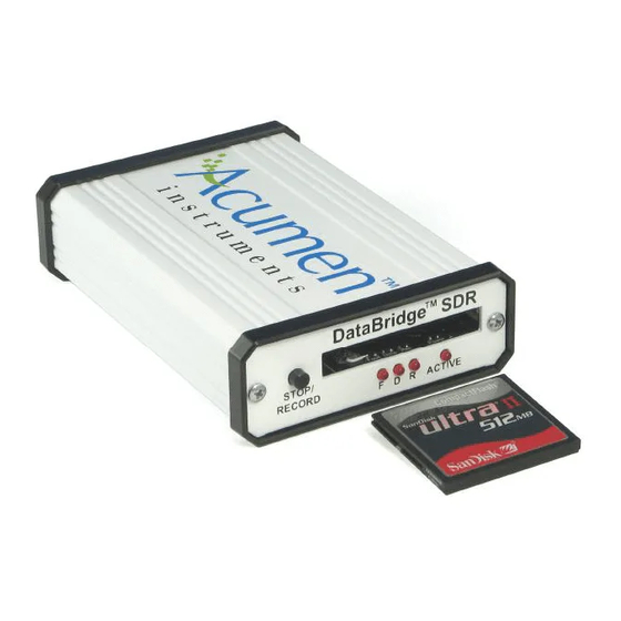
Configuring the DataBridge SDR2-CF Getting Started 1.1 Overview DataBridge SDR2-CF serial data recorders record RS-232 serial data to industry-standard mass storage using an MS-DOS™/Windows™-compatible FAT file format. The SDR2-CF (and SDR2-OEM-CF) is an SDR2-CF equipped with a Type I or II CompactFlash (CF) socket and is designed for use with CompactFlash storage media. -
Page 8: Before You Start
• A computer or terminal with an available serial port 1.3 A quick guide to the DataBridge SDR2-CF On the front of the SDR2-CF are the CF socket, record button, and LED indicators. The SDR2-CF can be toggled in and out of record mode using the record button located on the front panel. - Page 9 SDR2-CF/SDR2-OEM-CF Configuration Guide rev 1.0 Configuring the DataBridge SDR2-CF On the rear are two serial ports – one female nine-pin D-subminiature NOTE: The connector (DB9F) for the configuration port and one male nine-pin D- configuration and data subminiature connector (DB9M) for the data port. The 7 to 30 VDC power ports can each operate input is also located on the rear panel.
-
Page 10: Deploying The Databridge Sdr2-Cf
Configuring the DataBridge SDR2-CF SDR2-CF/SDR2-OEM-CF Configuration Guide rev 1.0 1.4 Deploying the DataBridge SDR2-CF 1.4.1 Connecting power to your SDR2-CF The SDR2-CF starter kit includes a 120VAC power supply that connects via the rear panel. If you use an alternate power source, it should be capable of sourcing at least 1W. - Page 11 SDR2-CF/SDR2-OEM-CF Configuration Guide rev 1.0 Configuring the DataBridge SDR2-CF with it. Typical communications software used is HyperTerminal™ which is included with Microsoft Windows 95/98/NT 4.0/2000/XP. Many other terminal programs are widely available for Windows, DOS, linux, and other platforms. To access HyperTerminal, click the Windows start button and choose Programs, then Accessories, then Communications, and then HyperTerminal.
- Page 12 Configuring the DataBridge SDR2-CF SDR2-CF/SDR2-OEM-CF Configuration Guide rev 1.0 Figure 1.5. The default settings under the New Connection Properties tab in HyperTerminal. Figure 1.6. The SDR2-CF Configuration menu in HyperTerminal with ANSI mode ON. Congratulations! You are now talking to the SDR2-CF and can begin...
-
Page 13: Configuring The Databridge Sdr2-Cf
SDR2-CF/SDR2-OEM-CF Configuration Guide rev 1.0 Configuring the DataBridge SDR2-CF Configuring the DataBridge SDR2-CF Now that you have access to the SDR2-CF’s menu system, you are ready to configure it for use with your serial data source. Using the Configuration menu, you can: •... -
Page 14: Setting Date And Time
Configuring the DataBridge SDR2-CF SDR2-CF/SDR2-OEM-CF Configuration Guide rev 1.0 2.1 Setting date and time The SDR2-CF features a real-time clock that reports a file’s last modified TIP: For detailed date and time. The real-time clock is preset and battery-backed, so setting information about the the date and time is seldom necessary. -
Page 15: Configuring The Data Port
SDR2-CF/SDR2-OEM-CF Configuration Guide rev 1.0 Configuring the DataBridge SDR2-CF Figure 2.2. Setting the SDR2-CF’s date. 2.2 Configuring the data port Before the SDR2-CF and your data source can communicate, they must interact at the same data rate and using the same data format. -
Page 16: Specifying A Filename And Folder
Configuring the DataBridge SDR2-CF SDR2-CF/SDR2-OEM-CF Configuration Guide rev 1.0 the H or D commands. Press <Enter> to save the changes and close the window. To change the baud rate and hardware handshaking for the data port, type 9, and select the appropriate settings to for your data source. -
Page 17: Setting Recording Parameters
SDR2-CF/SDR2-OEM-CF Configuration Guide rev 1.0 Configuring the DataBridge SDR2-CF submenu (see Figure 2.4). You can use Option 3 to change directory without having to retype the filename. From the File System Functions menu, press 2. Then, when prompted, backspace over the current filename/path and type a filename, pressing the <Enter>... - Page 18 Configuring the DataBridge SDR2-CF SDR2-CF/SDR2-OEM-CF Configuration Guide rev 1.0 Figure 2.5. The Recording Parameters submenu. Overwrite-oldest mode: When overwrite is enabled, the SDR2-CF will delete the oldest file on the disk whenever recording starts and the CF card has less than 1 megabyte of free disk space.
- Page 19 SDR2-CF/SDR2-OEM-CF Configuration Guide rev 1.0 Configuring the DataBridge SDR2-CF Append mode: If append mode is enabled, data will be recorded to the current file whenever recording starts, resulting in one large file. New files will only be created when the filename is modified via the configuration menus.
- Page 20 Configuring the DataBridge SDR2-CF SDR2-CF/SDR2-OEM-CF Configuration Guide rev 1.0 Figure 2.8. Configuring the SDR2-CF to create a new file every hour (3600 seconds). Time stamping: This option is most commonly used when logging ASCII data to add date and time to the beginning of each line of data, which is useful for correlating data with other recorders.
-
Page 21: Entering Messages
SDR2-CF/SDR2-OEM-CF Configuration Guide rev 1.0 Configuring the DataBridge SDR2-CF Figure 2.9. Configuring the time stamping for ASCII data with CR+LF line ends. Powering up in passthrough mode: This option forces the SDR2-CF into NOTE: From the main passthrough mode (as if the user had pressed 8 from the main configuration... -
Page 22: Setting Message Parameters
Configuring the DataBridge SDR2-CF SDR2-CF/SDR2-OEM-CF Configuration Guide rev 1.0 Messages are stored as ASCII text strings in non-volatile memory. To use messages, first enter a text string for one of the ten messages. Then, configure whether the message should be sent on when recording starts, when recording stops, or at an interval specified in seconds. - Page 23 SDR2-CF/SDR2-OEM-CF Configuration Guide rev 1.0 Configuring the DataBridge SDR2-CF Initialization: Some devices “wake up” or begin continuously sending data only after receiving a specific command, the initialization string. When prompted, press Y to indicate that the SDR2-CF should send the message once when it enters record mode.
-
Page 24: Testing Your Configuration
Configuring the DataBridge SDR2-CF SDR2-CF/SDR2-OEM-CF Configuration Guide rev 1.0 2.6 Testing your configuration To test your configuration, disconnect your terminal from the configuration TIP: Messages with port and use a null modem adapter or cable to connect your terminal to the only a carriage return data port. -
Page 25: Operations
SDR2-CF/SDR2-OEM-CF Configuration Guide rev 1.0 Operations Operations 3.1 Record mode When you press the record button or type R from the Configuration menu, the SDR2-CF searches for the current file specified in the File System Functions menu, creates it if necessary, and opens it. Once the SDR2-CF has successfully opened the file, the record indicator turns on and the SDR2- CF enters record mode. -
Page 26: Stopping Recording
Operations SDR2-CF/SDR2-OEM-CF Configuration Guide rev 1.0 3.1.2 Stopping recording Incoming data is appended to the open file as it is received until you stop recording by either pressing the record button or typing S from the Configuration menu. The SDR2-CF then closes the file, updates its directory entry (recording file size, date, and time), and returns to stop mode. -
Page 27: Partitions
SDR2-CF/SDR2-OEM-CF Configuration Guide rev 1.0 Operations Figure 3.1. Formatting a CompactFlash card using the FAT file system. 3.1.6 Partitions In some cases, disks are partitioned to contain multiple "virtual" drives on a single disk. Partitioning is sometimes done to overcome the 2 gigabyte size limit in MS-DOS™... -
Page 28: Lithium Battery Maintenance
Operations SDR2-CF/SDR2-OEM-CF Configuration Guide rev 1.0 To change the configuration port baud rate, open the enclosure and use switches S1-1, S1-2 and S1-3 to select a baud rate for the configuration port and switch S1-4 to enable or disable RTS/CTS hardware handshaking. See 3.1 for switch settings. -
Page 29: Configuration Menu Reference
SDR2-CF/SDR2-OEM-CF Configuration Guide rev 1.0 Configuration Menu Reference Configuration Menu Reference You can use menu functions to manage files, configure and communicate with the device attached to the data port, set date and time, set up output messages, download data, configure the storage media, and control the SDR2-CF without using the record button. -
Page 30: Set Time
Configuration Menu Reference SDR2-CF/SDR2-OEM-CF Configuration Guide rev 1.0 Figure 4.1. The DataBridge SDR2--CF configuration menu. 4.1.1 Set Time To update the real-time clock’s time, type 1 at the menu prompt. When prompted further, enter the time in 24-hour format using two digits for each of hours, minutes, and seconds (omit the colons (:) between each field). -
Page 31: Enter Serial Passthrough Mode
SDR2-CF/SDR2-OEM-CF Configuration Guide rev 1.0 Configuration Menu Reference messages off does not change their settings, but overrides the current message parameters. The current state of the messages is indicated. NOTE: Incorrect 4.1.5 Enter Serial Passthrough Mode handshaking settings may cause the Serial passthrough mode provides a means for communicating with the SDR2-CF to become device connected to the data port. -
Page 32: Edit Messages Menu
Configuration Menu Reference SDR2-CF/SDR2-OEM-CF Configuration Guide rev 1.0 4.2 Edit Messages menu To enter the Edit Messages submenu, type 5 from the Configuration menu. The Edit Messages menu appears (see Figure 4.3). To edit a message’s contents, type 1. Select the number of the message you would like to edit and type in the new message contents. -
Page 33: Recording Parameters Menu
SDR2-CF/SDR2-OEM-CF Configuration Guide rev 1.0 Configuration Menu Reference Figure 4.4. Changing the parameters for message 0. From the main configuration menu (see Figure 4.1), typing 4 enables or disables all messages. If you are using the message feature, be sure the main menu displays “messages are ON”... -
Page 34: Change Current Filename
Configuration Menu Reference SDR2-CF/SDR2-OEM-CF Configuration Guide rev 1.0 Figure 4.5. The Recording Parameters submenu. From the Recording Parameters submenu, you can specify a filename, control how new files are created and named, how the SDR2-CF deals with a full CF card, whether timestamps are added to incoming data, and whether the configuration port displays the menu or communicates with the data source during recording. -
Page 35: Set Scheduled File Close Parameters
SDR2-CF/SDR2-OEM-CF Configuration Guide rev 1.0 Configuration Menu Reference new file. Menu option 3 turns append mode on and off. The menu displays the state of append mode. When append mode is off, the SDR2-CF will generate a name for the new file based on the current filename. - Page 36 Configuration Menu Reference SDR2-CF/SDR2-OEM-CF Configuration Guide rev 1.0 Figure 4.7. Configuring scheduled file close for every 3600 seconds (1 hour) of recording time. Table 4.1 provides useful conversion factors for specifying file-closing intervals. Interval Seconds 1 second 1 minute 1 hour 3600 1 day 86400...
-
Page 37: Time Stamp Incoming Lines
SDR2-CF/SDR2-OEM-CF Configuration Guide rev 1.0 Configuration Menu Reference Figure 4.8. Configuring scheduled file close every 1 megabyte (1048576 bytes) of data received. 4.3.5 Time stamp incoming lines The SDR2-CF allows you to add the time and date to each line of incoming data. - Page 38 Configuration Menu Reference SDR2-CF/SDR2-OEM-CF Configuration Guide rev 1.0 Figure 4.9. Enabling time stamping of incoming data after the line feed (LF) character. Figure 4.10 shows an ASCII download of a file with time stamping enabled. Figure 4.10. An example of a file recorded with time stamping enabled.
-
Page 39: Power Up In Passthrough Mode
SDR2-CF/SDR2-OEM-CF Configuration Guide rev 1.0 Configuration Menu Reference 4.3.6 Power up in passthrough mode In some unique applications, the user may wish to always communicate with the data source via the configuration port using passthrough mode. For example, if the SDR2-CF is placed "in-line" between a computer or microprocessor to log communications to or from each. -
Page 40: Display Root Directory
Configuration Menu Reference SDR2-CF/SDR2-OEM-CF Configuration Guide rev 1.0 4.4.1 Display root directory To display the current directory, type 1. If the directory is not empty, each file’s name, attributes, last modified time/date, and file size in bytes is shown (see Figure 4.12). Once the directory has been displayed, press any key to return to the File System Functions menu. -
Page 41: Rename Current File
SDR2-CF/SDR2-OEM-CF Configuration Guide rev 1.0 Configuration Menu Reference 4.4.5 Rename current file To rename a file on the storage media, specify its filename using menu option 2, and then press 5. When prompted, enter a new name for the file. 4.4.6 Download directory via Ymodem batch Menu option 6 allow you to download all files in the current directory using... - Page 42 Configuration Menu Reference SDR2-CF/SDR2-OEM-CF Configuration Guide rev 1.0 Figure 4.14. Preparing to download a directory using HyperTerminal. Once you have chosen to receive a file, you must specify a location where HyperTerminal will put the files that are downloaded and the receiving protocol, Ymodem (see Figure 4.15).
-
Page 43: Download File As Ascii Text
SDR2-CF/SDR2-OEM-CF Configuration Guide rev 1.0 Configuration Menu Reference Figure 4.16. Ymodem download in progress in HyperTerminal. 4.4.7 Download file as ASCII text You can use menu option 7 to download or view a file. ASCII downloading You may wish to doesn’t provide error checking, but is useful for displaying short files or for disable ANSI mode downloading using terminal software that doesn’t support Ymodem. - Page 44 Configuration Menu Reference SDR2-CF/SDR2-OEM-CF Configuration Guide rev 1.0 Figure 4.17. Downloading a file as ASCII text. In HyperTerminal, you can capture the ASCII text to a file by selecting “Capture Text…” from the “Transfer” menu item (see Figure 4.18), and then specifying a filename for the captured text (see Figure 4.19).
- Page 45 SDR2-CF/SDR2-OEM-CF Configuration Guide rev 1.0 Configuration Menu Reference Figure 4.19. Specifying a filename for an ASCII file transfer in HyperTerminal.
-
Page 47: J4 Remote Control Port
SDR2-CF/SDR2-OEM-CF Configuration Guide rev 1.0 Configuration Menu Reference J4 Remote Control Port 5.1 Overview The SDR2-CF’s J4 remote connector allows for starting and stopping recording via external switJoel Cches/buttons or TTL/CMOS digital logic. The J4 connector also provides alternate outputs for the front-panel fault, data, and record indicators. -
Page 48: Pinout And Mating Cable
Table 5.1. J4 remote control port pin functions. 5.4 Pinout and Mating Cable The J4 connector is a 2mm 10-pin connector housing that mates to a Hirose DF11-10DS-2C shell (Digi-Key part number H2023-ND). A pre-built J4 cable is available from Acumen Instruments Corporation on request. -
Page 49: Force-Record Shunt Installation
SDR2-CF/SDR2-OEM-CF Configuration Guide rev 1.0 Configuration Menu Reference Contact Function Direction Wire Color (3.3 VDC) GND (0 VDC) Black REC_BUTTON input Blue REC_TOGGLE input Grey FAULT output Yellow no connect DATA output Orange RECORD output Green (3.3 VDC) GND (0 VDC) Table 5.2. -
Page 51: Service And Support
SDR2-CF/SDR2-OEM-CF Configuration Guide rev 1.0 Service and Support Service and Support 6.1 Exception Codes The following are common error codes encountered when using DataBridge SDR2-CF and SDR2-OEM-CF products. To determine which error has occurred, watch the "exception" indicator on the SDR2-CF's front panel and count the number of rapid blinks. -
Page 52: Exception 5: Hardware Error
Try ejecting and reinserting the card or using a new card and contact Acumen if problem persists. Exception 6: EEPROM Error Rare hardware error. Contact Acumen to discuss repair or replacement. Exception 7: Cache Error Rare hardware error. Contact Acumen to discuss repair or replacement. -
Page 53: Contacting Acumen Instruments Corporation
Corporation can be reached at the following phone numbers: (515) 296-5366 (voice) (515) 296-3554 (fax) 6.2.2 U.S. Mail Acumen Instruments Corporation can be reached by mail at: Acumen Instruments Corporation 2625 N. Loop Drive Suite 2200 Ames, IA 50010 6.2.3... -
Page 54: Warranty
6.4 Warranty 6.4.1 One year warranty Acumen Instruments Corporation warrants this product to be free from defects in materials and workmanship for a period of one (1) year from the date of shipment. During the warranty period, Acumen Instruments Corporation will, at its option, either repair or replace products that prove to be defective. -
Page 55: Serial Port Basics
SDR2-CF/SDR2-OEM-CF Configuration Guide rev 1.0 Serial Port Basics A.Serial Port Basics A.1 Serial specifications Serial data is any data that is sent one bit at a time using a single electrical signal. In contrast, parallel data is sent 8, 16, 32, or even 64 bits at a time using a signal line for each bit. -
Page 56: Data Rates And The Uart
Serial Port Basics SDR2-CF/SDR2-OEM-CF Configuration Guide rev 1.0 The EIA RS-232C standard permits data rates up to 19200 bps and cable lengths up to 400 meters (but not both). data rate maximum distance (bps) (meters) (feet) 19200 9600 4800 2400 1200 1216 Table A.1. -
Page 57: Dte And Dce
SDR2-CF/SDR2-OEM-CF Configuration Guide rev 1.0 Serial Port Basics To transfer data asynchronously, the UART frames the 8 data bits between a stop bit and a start bit. The start bit is always a zero, while the stop bit is always a one. So, a byte of data sent serially is made up of 10 bits instead of the usual 8. -
Page 58: Handshaking
Serial Port Basics SDR2-CF/SDR2-OEM-CF Configuration Guide rev 1.0 modem cable because it can connect two terminals (DTE’s) without the use of modems (DCE’s). Note that GND pins are always connected. Most devices have female connectors (DB9 or DB25) if they are configured for DCE operation and male connectors if they are configured for DTE operation, but this is not always the case. - Page 59 SDR2-CF/SDR2-OEM-CF Configuration Guide rev 1.0 Serial Port Basics CTS, etc.), RS-232 devices use +3V to +25V to assert the signal and –3V to –25V to deassert the signal. These voltage levels are defined in the EIA/TIA- 232E specification. So, when a DTE devices drives RTS at –9.50V, it is signaling the DCE to stop sending data.
-
Page 61: Sdr2-Cf And Sdr2-Oem-Cf Specifications
Recording in Low Power Mode +10 VDC sheet Idle in Low Power Mode +10 VDC Table B.1. DataBridge SDR2-CF power consumption with CompactFlash card installed. B.1.5 J7 rear power receptacle pin configuration Function +5 to +30 VDC ring Ground Table B.2. -
Page 62: J1 Power Receptacle Pin Configuration
Specifications SDR2-CF/SDR2-OEM-CF Configuration Guide rev 1.0 B.1.6 J1 power receptacle pin configuration Function +5.0 to +30 VDC Ground Table B.3. The SDR2-OEM-CF power receptacle pin configuration. B.2 Serial communications Serial Port electrical interface compliance EIA/TIA-232E and V.28 data rates 50 to 921600 baud data bits 7 or 8 stop bits... - Page 63 Specifications SDR2-CF/SDR2-OEM-CF Configuration Guide rev 1.0 Notes:...
Need help?
Do you have a question about the DataBridge SDR2-CF and is the answer not in the manual?
Questions and answers