Table of Contents
Advertisement
Advertisement
Table of Contents
Troubleshooting

Related Manuals for Secure Power SP201

Summary of Contents for Secure Power SP201
-
Page 1: User Manual
Secure Power Ltd User Manual SP200 Low Power UPS SP201 SP202 SP203 Secure Power Ltd Moorgate Crofts Business Centre, South Grove, Rotherham, S60 2DH, UK Telephone: 0844 567 9770 Fax: 0844 567 9771 Email: sales@secure-power.co.uk Website: www.secure-power.co.uk... - Page 2 Secure Power Ltd User Manual THIS PAGE HAS BEEN INTENTIONALLY LEFT BLANK...
-
Page 3: Table Of Contents
Secure Power Ltd User Manual 1.0 Safety instruction ..........................3 1.1 Safety instruction ........................3 1.2 Symbols ..........................3 2.0 Product Introduction ......................... 4 2.1 The appearance of the product ..................... 4 2.2 The principle of the product ....................5 2.3 Model ............................ -
Page 4: Safety Instruction
The UPS should be kept in a dry, well-ventilated location, away from any area where the fire hazard may be acute and out of direct sunlight or other sources of heat. Should the UPS at any time emit smoke, isolate the power immediately and contact Secure Power Ltd. 1.2 Symbols The safety symbols cited in this manual are shown in table below, these are used to inform readers of safety issues that should be followed when carrying out installation, operation and maintenance. -
Page 5: Product Introduction
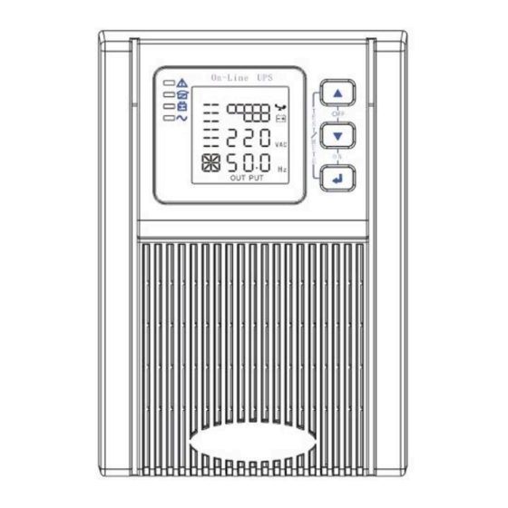
Secure Power Ltd User Manual 2.0 Product Introduction 2.1 The appearance of the product Fig 1. Front Panel view Fig 2. 1KVA Rear Panel view Fig 3. 2KVA/3KVA Rear Panel view Fig 4. Output Socket Type... -
Page 6: The Principle Of The Product
Secure Power Ltd User Manual 2.2 The principle of the product Fig 5. UPS Principle Diagram Input filter: Complete filtering the input AC utility power to provide the clean power for UPS. AC/DC converter: Convert the filtered AC mains to DC and boost the DC for DC/AC inverter. -
Page 7: Installation
3.1 Unpacking and inspection 1. Unpack the UPS and check that it has not been damaged during transportation. If damage has occurred or parts are missing, inform Secure Power Ltd immediately. 2. Check the annex (please consult Appendix Table 1). -
Page 8: Ups Output Connection
Secure Power Ltd User Manual 3.4 UPS output connection Fig 7. Output connection 3.5 Long backup external battery connection Fig 8. Battery connection... - Page 9 Secure Power Ltd User Manual Warning: ► Before installing the battery, make sure that UPS and breaker are turned off. Remove all any metallic objects such as rings, watches and so on before connecting. ► No anti-connection or short circuit between the battery anode and cathode forever. Red cable connect with battery anode “+”...
-
Page 10: Panel Display, Operation And Running
Secure Power Ltd User Manual 4.0 Panel display, operation and running The operation of the UPS is simple, no special training is required. Operators only need to read the manual and follow the simple operation instructions. 4.1 Faceplate display illumination 4.1.1 Keys function... - Page 11 Secure Power Ltd User Manual Non-function setting mode: Press and hold the key for more than 2 seconds: Function setting interface. Function setting mode: Press and hold the key for more than half a second (less than 2 seconds): Affirm the set option.
-
Page 12: The Function Of Led Indicators
Secure Power Ltd User Manual 4.1.2 The function of LED indicators Warning red LED is on: UPS is fault. For example: Overload beyond the allowed time, inverter fault, BUS fault, over temperature fault etc. Bypass yellow LED is on: UPS is alarming. For example: Bypass mode supply power and etc. -
Page 13: Operation
Secure Power Ltd User Manual Numerical value section-display the corresponding numerical value of inquiring items(output, load, temperature, input, battery), for example, as the graphics shows above, the output voltage is 220v, the output frequency is 50Hz. Capacity graphics section-display the capacity of the battery and load. Every pane represents 20%capacity. -
Page 14: Turn Off Operation
Secure Power Ltd User Manual Once mains power is plugged in, the UPS will charge the battery, at the moment, LCD shows that the output voltage is 0, which means UPS has no output. If it is expected to have output of bypass, you can set the bps “ON”... - Page 15 Secure Power Ltd User Manual Enter the ECO setting interface. Press and hold the function setting key for more than half a second (less than 2 seconds), then come to setting interface of ECO, at this time, the letters “ECO”...
-
Page 16: Bypass Mode Setting
Secure Power Ltd User Manual 4.3.2 Bypass mode setting Enter the setting interface. Press and hold the function setting key for more than 2 seconds, then come to setting interface, Press and hold the function setting key for more than half a second(less than 2 seconds), select the function setting, choose the bypass output interface, at the moment, the letters “bPS”... -
Page 17: Output Voltage Setting
Secure Power Ltd User Manual Exit from the setting interface. Press and hold function setting key for more than 2 seconds, exit from the setting interface and return to main interface. After setting bPS as ON, when mains power plugged in without turning on the UPS or no mains power plugged in, there is bypass output but no power down backup function. -
Page 18: Parameters Inquiring
Secure Power Ltd User Manual Confirm the output voltage selecting interface. After selecting numerical value, press and hold the function setting key for more than half a second (less than 2 seconds). Now, the OPU setting function is completed and the numerical value below the “OPU” will light without flash. - Page 19 Secure Power Ltd User Manual Load: Display the numerical value of the active power (WATT) and apparent power(VA) of the load. For example, as the following graphics shows: the WATT of the load is 100w, VA is 100VA (when disconnect load, it is a normal phenomenon to show a small numerical value of WATT and VA).
-
Page 20: Run Mode
Secure Power Ltd User Manual Battery: Display the voltage and capacity of the battery (determined by type). As the following graphics shows: the battery voltage is 28v, the capacity of battery is 100%(the capacity of battery is approximately reckoned according to the battery voltage). -
Page 21: Line Mode
Secure Power Ltd User Manual Bypass yellow LED is on, the buzzer beeps once every 2 minutes. The warning red LED is on when beeping, LCD displays are according to the exact load and battery capacity. Turn to bypass mode under the following two conditions: Turn off the UPS in line mode while start the bypass output. -
Page 22: Battery Mode
Secure Power Ltd User Manual 4.5.3 Battery mode LED indications on front panel in battery mode are as following: both the inverter green and battery yellow LED’s are on, the buzzer beeps once every 4 seconds. The warning red LED is on when beeping. - Page 23 Secure Power Ltd User Manual key to make the buzzer stop beeping temporarily to wait for maintenance. You can also press the OFF key to shut down the UPS when confirm that there is no serious fault. NOTE: As for corresponding information of the fault code, please refer to Fault Code information Table in Appendix.
-
Page 24: Maintenance
Secure Power Ltd User Manual 5.0 Maintenance This series of UPS requires minimum maintenance as the batteries are maintenance free sealed lead acid. It only needs to be kept charged to obtain the expected life. Whether it is started or not, the UPS would charge batteries once it is connected to mains and provides protection for over-charging and deep discharging. -
Page 25: Troubleshooting And Performance Of Product
Secure Power Ltd User Manual 6.0 Troubleshooting and performance of product Users can judge if the fault is caused by external factors and know how to deal with it by making full use of the information: Fault indicator on, indicates that the UPS has detected some faults. -
Page 26: Appendix 2: The Corresponding Working Status Of Indications
Secure Power Ltd User Manual Appendix 2: The corresponding working status of indications Indication Working status Warning Remarks Bat Bps Fau Line mode Normal voltage ● None High/low voltage Once every protection, turn to ● ● ► four seconds battery mode... -
Page 27: Troubleshooting
8 hours, recharge battery Check the usage of loads, remove some Short back up time UPS overload redundant devices When replace battery, contact Secure Power Ltd Battery aged to get battery and relative assembly Didn’t press the combination keys of Press the two keys at the same time “on”... -
Page 28: Product Performance
Secure Power Ltd User Manual 6.4 Product Performance Model 1KVAS 1KVAH 2KVAS 2KVAH 3KVAS 3KVAH Rated capacity 700W/1000VA 1400W/2000VA 2100W/3000VA Input Single phase and earthing Voltage range 115±5VAC-295±5VAC Frequency range 45Hz-55Hz@50HZ/55Hz-65Hz@60HZ Power factor ≥0.98 Input ECO range Setting output voltage ±20VAC... -
Page 29: Communication Interface
Secure Power Ltd User Manual Work Environment Model 1KVA-3KVA series Temperature 0 ~40 Relative Humidity 0~95% non-condensing Altitude <1500m. when >1500m, lower the rated power Store temperature for use -25 ~55 Mechanical Specification Dimension W x D x H Net weight/Gross... -
Page 30: Optional Communication Interface
Secure Power Ltd User Manual 6.5.3 Optional communication interface USB communication interface Install the intelligent monitoring software UPSilon2000 which is equipped with the UPS. Then it can achieve the communication with monitoring device directly. When RS232 and USB are provided, only one of them will be chosen and USB is preferred.
Need help?
Do you have a question about the SP201 and is the answer not in the manual?
Questions and answers