Table of Contents
Advertisement
A Better Built Machine.
Owner's Manual
Parts Manual
READ THIS MANUAL CAREFULLY,
IT CONTAINS IMPORTANT SAFETY INFORMATION.
INTERCEPTOR GTR 250
This kart is designed for off-road use only
and does not comply with Federal Motor Vehicle Safety Standards.
Recommended for Ages 16+
C-GTR-2861-LIVE AXLE-003-03-2007
MODEL:2861-Live Axle
Advertisement
Table of Contents

Related Manuals for Carter INTERCEPTOR GTR 250


Summary of Contents for Carter INTERCEPTOR GTR 250
- Page 1 Owner’s Manual Parts Manual READ THIS MANUAL CAREFULLY, IT CONTAINS IMPORTANT SAFETY INFORMATION. INTERCEPTOR GTR 250 MODEL:2861-Live Axle This kart is designed for off-road use only and does not comply with Federal Motor Vehicle Safety Standards. Recommended for Ages 16+...
- Page 2 Failure to follow the warnings contained in this manual could result in serious injury or death. The Interceptor GTR 250 fits the needs of a wide variety of kart users above 16 years old. Beginners should seek instruction from your dealer or qualified instructors before and during intial use of the kart.
-
Page 3: Table Of Contents
INDEX Owner’s Manual Warranty About Safety Important Safety Information Safety Labels Are You Ready To Drive? Is Your Vehicle Ready To Drive? Safe Driving Precautions General Informations Specifications Locations Of Parts Operation Periodical Checks And Services Service Instructions Service Information Wiring Diagram Trouble Shooting Charts Set-up Instructions... - Page 4 INDEX Services Manual General Information Service Maintenance Information Lubrication System Fuel System Cylinder Head / Valve Cylinder / Pistion “V” Type Belt Driving System / Kick-Starter Final Driving Mechanism Alternator Crankshaft / Crankcase 10.1 Cooling System 11.1 Electrical Equipment 12.1...
-
Page 5: Warranty
To register your product, complete the Warranty Registration form. Fax or mail the warranty registration form with a copy of the sales receipt to Carter. A warranty registration form be on file with Carter before a warranty claim can be processed. - Page 6 WARRANTY COVERAGE Carter Brothers Manufacturing, Inc. will repair or replace, at its option, any part that is found defective in material or factory workmanship under normal use.
- Page 7 We do not charge for parts for authorized warranty repairs. Any defective parts from repairs are required to be returned to Carter upon request. All warranties are voided if the vehicle has been altered for use in racing or competition, rented, used under abnormal conditions, or subject to abuse, misuse, neglect or improper maintenance.
- Page 8 A Better Built Machine. W arranty registration must be filed with Carter Brothers Manufacturing within 10 days of purchase or warranty will be void. In order to validate the warranty, purchaser agrees and promises to hold Carter Brothers Manufacturing and the Dealer harmless...
-
Page 9: About Safety
ABOUT SAFETY In order to keep everyone safe, you must take responsibility for the safe operation of your kart. To help you make informed decisions about safety, we have provided operating procedures and other information on labels and in this manual. This information alerts you to potential hazards that could hurt you or others. -
Page 10: Important Safety Information
IMPORTANT SAFETY INFORMATION Your kart will provide you with many years of service and pleasure, providing you take responsibility for your own safety and understand the challenges you may meet while driving. There is much that you can do to protect yourself while operating your kart. You'll find many helpful recommendations throughout this manual. - Page 11 IMPORTANT SAFETY INFORMATION Drive within Your Limits Pushing limits is another major cause of kart accidents. Never drive beyond your personal abilities or faster than conditions warrant. Remember that alcohol, drugs, fatigue, and inattention can significantly reduce your ability to make good judgments and drive safely.
-
Page 13: Are You Ready To Drive
ARE YOU READY TO DRIVE ? Before each drive, make sure you and your kart are both ready to drive. This section discusses how to evaluate your driving readiness, what items you should check on your kart, and adjustments to make for your comfort, convenience, or safety. Before you drive your kart for the first time, we urge you to: Read this owner's manual and the labels on your kart carefully. - Page 14 ARE YOU READY TO DRIVE? Additional Driving Gear In addition to a helmet and eye protection, we also recommend: Sturdy off-road motorcycle boots to help protect your feet, ankles, and lower legs. Off-road motorcycle gloves to help protect your hands. Driving pants with knee and hip pads, a driving jersey with padded elbows, and a chest/ shoulder protector.
-
Page 15: Is Your Vehicle Ready To Drive
IS YOUR VEHICLE READY TO DRIVE? Before each drive, it is important to inspect your kart and make sure any problems you find are corrected. A pre-drive inspection is a must, not only for safety, but because having a breakdown, or even a flat tire, can be a major inconvenience. If your kart has overturned or has been involved in a collision, do not drive it until your kart has been inspected by your dealer. - Page 16 IS YOUR VEHICLE READY TO DRIVE? Leaks, Loose Parts Walk around your kart and look for anything that appears unusual, such as a leak or loose cable. Lights Make sure the headlights, brake light, and tail light are working properly. Throttle Check the freeplay and adjust if needed.
-
Page 17: Safe Driving Precautions
SAFE DRIVING PRECAUTIONS Off-Road Use Only Your kart and its tires are designed and manufactured for off-road use only, not for pavement. Driving on pavement can affect handling and control. You should not drive your kart on pavement. WARNING Operating this kart on paved surfaces may seriously affect handling and control of the kart, and may cause the vehicle to go out of control. - Page 18 SAFE DRIVING PRECAUTIONS Control Speed Driving at excessive speeds increases the chance of an accident. In choosing a proper speed, you need to consider the capability of your kart, the terrain, visibility and other operating conditions, plus your own skills and experience. WARNING Operating this kart at excessive speeds increases your chances of losing control of the kart, which can result in an accident.
-
Page 19: General Information
GENERAL INFORMATION MODEL IDENTIFICATION FRAME NUMBER The frame number or VIN is stamped on the upper firewall of the frame behind the seat. VIN NUMBER LOCATION ENGINE NUMBER The engine number is located on the lower front left side of the engine case. FUEL RECOMMENDATIONS FUEL Gasoline should be 92 octane or higher. -
Page 20: Specifications
SPECIFICATIONS DIMENSIONS Overall Length ---------------------------------------------------------------------------- 90 in. (2286mm) Overall Width ---------------------------------------------------------------------------- 62 in. (15748mm) Overall Height ----------------------------------------------------------------------------- 63 in. (1600mm) Wheelbase ---------------------------------------------------------------------------------- 68 in. (1727mm) Front Track ------------------------------------------------------------------------------ 47.1 in. (1060mm) Rear Track ------------------------------------------------------------------------------- 39.4 in. (1000 mm) Ground Clearance ------------------------------------------------------------------------- 5.1 in. (130mm) ENGINE Type -------------------------------------------------------------------------------------------------- 4-Stroke Engine Capacity --------------------------------------------------------------------------------------- 250cc... - Page 21 CHASSIS Front, Rear Brake ----------------------------------------------------------------------------- Hydraulic disc Front Tire -----------------------------------------------------------------------------------------23x7-10 14psi Rear Tire ------------------------------------------------------------------------------------------25x7-12 14ps Front Suspension ---------------------------------------------------------------------------------Dual A-Arm Rear Suspension ---------------------------------------------------------------------------------Dual A-Arm Restraint System --------------------------------------------------------------------- Dual 4-point Harness Final Drive Chain -------------------------------------------------------------------------------- 520 x 66 WEIGHT Net Weight -----------------------------------------------------------------------------------------372kgs/819lbs *The specifications are subject to change without notice.
-
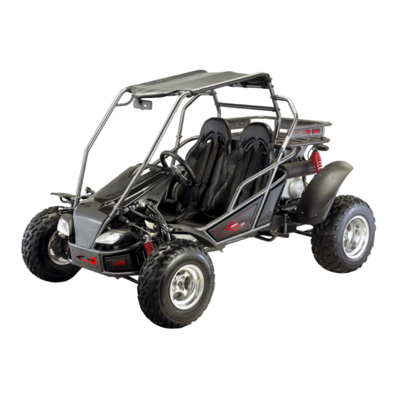
Page 22: Locations Of Parts
LOCATION OF PARTS MIRROR SEAT BELT HEADLIGHTS STEERING WHEEL R.R. WHEEL FR. WHEEL REAR CARGO RACK TOW BALL DRIVE CHAIN... - Page 23 LOCATION OF PARTS 12V OUTLET HORN KEY SWITCH HEADLIGHT SWITCH BLINKER ENGINE STOP BUTTON REAR CARGO RACK RADIATOR ENGINE FUEL TANK...
-
Page 24: Operation
OPERATION A. Operation Controls WARNING - Do not attempt to start or operate the engine until you are completely familiar with the location and use of each control necessary to operate this vehicle. The operator must know how to stop this machine before starting and driving it. a. - Page 25 OPERATION B. Pre-Drive Inspection WARNING Perform this pre-drive inspection everyday before driving vehicle. If not performed, serious damage to the vehicle or personal injury may result. a. Check engine oil level. Check for leaks, add oil if required. b. Check fuel level. Add fuel as necessary and do not overfill. Check for leaks. c.
- Page 26 OPERATION C. Passengers The vehicle allows for two riders only. Combined maximum weight of driver and the passenger should not exceed 180kg or 400lbs. D. Seat Adjustment The seat must always be securely fastened in the position which best affords the operator control of the foot pedals, steering wheel, and the remote stop button.
- Page 27 OPERATION F. Gear Shift Lever YOKE YOKE ADJUSTMENT a. Each end of the cable has a threaded yoke on it. b. You must remove the pin or bolt in either end of the cable to which the yoke is attatched. c.
-
Page 28: Starting
OPERATION G. Starting And Operating Instructions a. Before starting the engine, be sure that the driver is seated properly in the kart with the seat belt fastened. b. Test the kart in an open space at the beginning to learn how to start, turn, and stop. c. -
Page 29: Ignition
PERIODICAL CHECK AND SERVICES Have your kart checked, adjusted, and record maintenance performed.Have these services performed periodically by your Carter Authorized Dealer to maintain the kart at the optimum condition. Every 300km 1 Month 3 Months 6 Months 1 Year... -
Page 30: Torque Values
SE RVICE INSTRUCTIONS Torque Values The torque values listed in this table are for more important tighten torque values. Please see standard values for torques not listed in the table. Torque Tightening Char Kg.m Ib-ft Kg.m Ib-ft Diameter 1 ~2 0.1 ~0.2 0.7 ~1.5 1.5 ~3... -
Page 31: Service Instructions
SERVICE INSTRUCTIONS B. Engine Lubrication You must change the oil in the crankcase after the first 5 hours of operating your new engine and after 10 hours of use thereafter. This will insure proper lubrication of internal parts and prevent costly repairs due to excessive wear. WARNING Used oil must be disposed of at a proper collection center. -
Page 32: Spark Plug
SERVICE INSTRUCTIONS D. Carburetor Adjustment Never make unnecessary adjustments. The factory recommended settings are correct for most applications. WARNING Air screw was set at factory, so no adjustment is needed. Note the number of turns it takes to scew it all the way in for ease of installation. The parking brake must be used to stop the kart to perform the adjustments. - Page 33 SERVICE INSTRUCTIONS F. Cleaning Instructions Keep your kart clean. With clean rag, wipe off dirt and oil from around controls. Wipe off any spilled fuel and oil. Keep the engine clean of foreign objects, and be sure to check that air intake fan is free of debris for proper cooling.
- Page 34 SERVICE INSTRUCTIONS H. Adjustment of Front and Rear Shocks There are five adjustable positions on each shock. The default position is in the middle. a.Use a round nut wrench to adjust the shock. b.The tension of the shock spring will increase as you scew to the right.
-
Page 35: Service Information
SERVICE INFORMATION J. Front Wheel Replacement Do not disassemble the castle nuts when you replace the front wheels. It is only necessary to remove the four 4 lug nuts to remove the wheel. Tighten the nuts after replacing the wheels. Figure 7 Figure 7 Figure 11... - Page 36 SERVICE INFORMATION L. Front Wheel Alignment a. The front wheels should be “toe-in” from 1/8” to 1/4”. To check for alignment, measure distance A and B between the centerline (CL) of the wheels. The proper toe-in dimension A should be 1/8” – 1/4” greater than dimension B. b.
- Page 37 SERVICE INFORMATION M. Fuel Switch (Petcock) This vehicle has a manually operated fuel with three positions. Please follow maintenance procedures accordingly. a. Periodically clean the petcock externally with grease remover and water. b. Check for any leaks or seeping fuel. “ON”...
- Page 38 SERVICE INFORMATION O. Steering Shaft a. Remove nuts steering block rease inside of steer-block periodically. Needle Bearing Steering Column b. Loosen steering shaft, clamp nut and steering gear box. Steering Shaft Link Steering Gear Box Clamp Nut c. Remove steering shaft. Steering Shaft...
- Page 39 SERVICE INFORMATION P. Steering Gear Box and Ball HEAD AND STEERING GEAR BOX a. Remove four bolts on LH and RH clamp nut b. Remove and check ball head dust cover and and steering gear box. steering gear box for wear. Ball Head Dust Cover Steering Gear Box Bolts and Nuts...
- Page 40 SERVICE INFORMATION Q. Steering Knuckle Support a. Remove rubber dust cover of the knuckle support. Ball Head Dust Cover b. Check the grease of ball joint. Clean it if it is dirty and fill with grease. Filled With Grease c. Replace the steering knuckle support if the ball joint is loose or steering isn’t flexible. Steering Knuckle Support Ball Joint...
- Page 41 SERVICE INFORMATION R. Throttle and Brake Pedal a. Remove throttle, throttle pedal and axle nut, check for signs of wear. Replace if wear is present. b. Fill with grease in order to make the throttle and brake pedal swing more flexibly before installation. S.
-
Page 42: Cooling System
SERVICE INFORMATION V. Radiator WARNING While engine is running, never attempt to open the radiator filler cap. The pressurixed hot coolant may shoot out and cause serious scalding injury. No maintenance work is allowed to be performed unless the engine is completely cooled down. a. - Page 43 SERVICE INFORMATION X. Front Hubs a. Check seals for rips or tears and replace if any exist. b. Inspect bearings for ease of movement. If bearings are dirty or muddy, wash them in cleaning solvent and spin with your finger. c.
- Page 44 WIRING DIAGRAM Red/White White/Red Yellow/Red Blue/White White/Black...
-
Page 45: Trouble Shooting Charts
TROUBLE SHOOTING CHARTS A. Engine hard to start or can not be started. Check and Adjustment Fault Condition Probable Causes Loosen carburetor drain bolt to check if there is gasoline inside No fuel in fuel tank. the carburetor. Check if the pipes, fuel tank to carburetor, and intake vacuum, are clogged. -
Page 46: Alternator
TROUBLE SHOOTING CHARTS B. Engine Runs Sluggish (Speed does not pick up, lack of power). Check and Adjustment Fault Condition Probable Causes Try gradual acceleration and check engine speed. Air cleaner clogged. Poor fuel supply. Engine speed can be Engine speed can not be Lines in fuel tank evaporation system increased. - Page 47 TROUBLE SHOOTING CHARTS C. Engine Runs Sluggish (especially in low speed and idling) Check and Adjustment Fault Condition Probable Causes Check ignition timing (using ignition lamp). Abnormal Normal Incorrect ignition timing (malfunction of CDI or AC alternator). Adjust the air screw of carburetor.
- Page 48 TROUBLE SHOOTING CHARTS E. Clutch, Driving and Driving Pulley Probable Causes Fault Conditions Drive belt worn out or deformed. Ramp plate of movable drive face damaged. Engine can be started but Driving pulley spring broken. kart can not be moved. Clutch weights broken.
- Page 49 TROUBLE SHOOTING CHARTS G. Lose Power Check and Adjustment Fault Condition Probable Causes Raise wheels off ground and spin by hand. Brake dragging. Spin freely. Abnormal Drive chain too tight. Damaged wheel bearing. Wheel bearing needs lubrication. Check tire pressure. Normal.
-
Page 50: Set-Up Instructions
SET-UP INSTRUCTIONS INTERCEPTOR GTR 250 TOOLS NEEDED Floor jack Flat head screw driver Needle nose pliers Phillips head screw driver Protective gloves Adjustable wrench Metric wrench and socket set LIFT THE KART In order to assemble the front suspension and steering the unit must be lifted high enough to put the front tires on it. - Page 51 SET-UP INSTRUCTIONS INTERCEPTOR GTR 250 STEERING LINKAGE a. Attach each tie-rod end to the struts by inserting the ball joint studs into the steering arm of each strut. b. On each stud place flat washer, lock washer, tighten with 17mm wrench and lock with cotter pin and needle nose pliers.
- Page 52 SET-UP INSTRUCTIONS INTERCEPTOR GTR 250 CV SHAFT a. Slide the female end of each CV shaft over the male end of each side of the center axle. b. Lock into place with lock ring. The lock ring should already be in place on each end of the center axle.
- Page 53 SET-UP INSTRUCTIONS INTERCEPTOR GTR 250 STUMP GUARD AND TRAILER HITCH a. Place the stump guard under the rear suspension box/ under the rear sprocket. b. Align the 4 holes of the stump with the holes on the frame. c. Be sure all bolts are in place then tighten with 10mm and 12mm wrench.
- Page 54 SET-UP INSTRUCTIONS INTERCEPTOR GTR 250 REAR FENDERS a. Behind each seat is a mounting post for the rear fenders. b. Align the holes and slots of the fender bracket with those of the mounting post. c. Tighten with 10mm wrench.
- Page 55 SET-UP INSTRUCTIONS INTERCEPTOR GTR 250 BRUSH BARS a. Place the main bars in proper location by inserting the open ends over the bar mount posts on the frame. The bar mounting posts for the main bars are at the hood and behind the seat.
-
Page 56: Engine Oil
SET-UP INSTRUCTIONS INTERCEPTOR GTR 250 BATTERY a. Put on protective gloves b. Remove red strip covering acid ports from battery. c. Place funnel into acid ports on battery. Press acid container firmly into funnel allowing acid to flow into battery. - Page 57 SET-UP INSTRUCTIONS INTERCEPTOR GTR 250 FILL ING THE COOLING SYSTEM WITH COOLANT It is very important that you do not just fill the radiator and reservoir with coolant and begin to ride the unit. The cooling system MUST have all the air bled from it or the system will not cool the engine.
Need help?
Do you have a question about the INTERCEPTOR GTR 250 and is the answer not in the manual?
Questions and answers