LG Air Conditioner Installation Manual
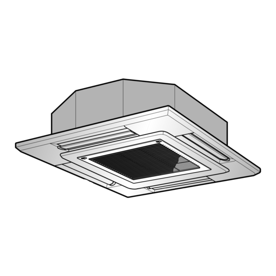
Cassette type
Hide thumbs
Also See for Air Conditioner:
- Owner's manual (64 pages) ,
- Installation manual (35 pages) ,
- Owner's manual (21 pages)
Table of Contents
Advertisement
LG Casstte Type
Air Conditioner
INSTALLATION MANUAL
website http://www.lgservice.com
IMPORTANT
• Please read this installation manual completely before
installing the product.
• Installation work must be performed in accordance with
the national wiring standards by authorized personnel
only.
• Please retain this installation manual for future reference
after reading it thoroughly.
LG
Advertisement
Table of Contents

Related Manuals for LG Air Conditioner


Summary of Contents for LG Air Conditioner
-
Page 1: Air Conditioner
LG Casstte Type Air Conditioner INSTALLATION MANUAL IMPORTANT • Please read this installation manual completely before installing the product. • Installation work must be performed in accordance with the national wiring standards by authorized personnel only. • Please retain this installation manual for future reference... -
Page 2: Table Of Contents
Cassette Type Air Conditioner Installation Manual TABLE OF CONTENTS Installation Required Parts Required Tools Requirements Safety Precautions ..3 Installation of Indoor, Outdoor unit ....6 • Connecting cable • Level • Four Type "A" Screw • Screw driver Ceiling opening • Hanging Bolt •... -
Page 3: Safety Precautions
Safety Precautions Safety Precautions To prevent injury to the user or other people and property damage, the following instructions must be followed. I Incorrect operation due to ignoring instruction will cause harm or damage. The seriousness is classified by the following indications. WARNING This symbol indicates the possibility of death or serious injury. - Page 4 Be sure the installation area does not Do not let the air conditioner run for a long time when deteriorate with age. the humidity is very high and a door or a window is left open.
- Page 5 Safety Precautions CAUTION I Installation Always check for gas (refrigerant) leakage after Install the drain hose to ensure that water is installation or repair of product. drained away properly. • Low refrigerant levels may cause failure of • A bad connection may cause water leakage. product.
-
Page 6: Installation Of Indoor, Outdoor Unit
• Ensure the spaces indicated by arrows 70cm( 27.6inch) from the wall, ceiling, fence or other obstacles. More than 50cm(19.7inch) More than 50cm(19.7inch) s t a c l e More than 50cm(19.7inch) More than 100cm (39.4inch) 6 Cassette type Air Conditioner... - Page 7 Installation of Indoor, Outdoor Unit 3. Piping length and the elevation Pipe Size Length A(m) Elevation B(m) *Additional Capacity (Diameter:Ø) refrigerant(g/m) Liquid Standard Max. Standard Max. 24k Btu/h 1/2"(12.7mm) 1/4"(6.35mm) 7.5(25') 30(100') 5(16') 15(50') 20(0.22 oz./ft.) 34k Btu/h 5/8"(15.88mm) 1/4"(6.35mm) 7.5(25') 35(115') 5(16')
-
Page 8: Ceiling Opening Dimensions And Hanging Bolt Location
• Make enough distance from a cooking room to install the air conditioner in such a place where it may not suck in oily steam. -
Page 9: The Indoor Unit Installation
The Indoor Unit Installation Ceiling Keep the length of the bolt Hanging bolt from the bracket to 40mm(1.57inch) (W3/8 or M10) Flat washer for M10 Air Conditioner body (W3/8 or M10) (accessory) Ceiling board Ceiling board Spring washer (M10) Flat washer for M10... -
Page 10: Wired Remote Control Installation
• Romove the batteries from the • Be sure that both batteries are new. remote controller if the air Re-attach the cover. conditioner is not going to be used • Slide it back into position. for some long time. 10 Cassette type Air Conditioner... -
Page 11: Wiring Connection
Wiring Connection Wiring Connection • Open the control box cover and connect the Remote controller cord and Indoor power wires. Indoor power cord Control box cover Remote controller [Air inlet side view] cord Control box cover screw 24k/34k Btu/h (1Ø) •... -
Page 12: Electrical Wiring
1. All wiring must comply with LOCAL REGULATIONS. 2. Select a power source that is capable of supplying the current required by the air conditioner. 3. Feed the power source to the unit via a distribution switch board designed for this purpose. -
Page 13: Connecting Pipes To The Indoor Unit
Connecting Pipes to the Indoor Unit Connecting Pipes to the Indoor Unit Preparation of Piping Main cause of gas leakage is defect in flaring work. Carry out correct flaring work in the Copper following procedure. Slanted Uneven Rough tube 90° 1. -
Page 14: Piping Connection
CAUTION: Use two wrenches and tighten with regular torque. Flare nut fastening torque 1.8kgf . m Ø6.35mm 1/4inch 2.7kgf . m Ø9.52mm 3/8inch Union 3.7kgf . m Ø12.7mm 1/2inch 4.7kgf . m Ø15.88mm 5/8inch 5.7kgf . m Ø19.05mm 3/4inch 14 Cassette type Air Conditioner... -
Page 15: Decorative Panel
4. Retighten completely two temporarily fixed screws and other two screws. (Total 4 screws) 5. Connect the louver motor connector and display connector. 6. After tightening these screws, install the air inlet grille (including the air filter). Air conditioner unit Piping side Install the panel after... -
Page 16: Indoor Unit Drain Piping
300mm(11.8inch) from the unit. Heat insulation material: Polyethylene foam with thickness more than 8 mm(0.31inch). Drain test The air conditioner uses a drain pump to drain water. Use the following procedure to test the drain pump operation: Flexible drain hose Feed water •... - Page 17 (over 120°C(248°F) ). 2. Precautions in high humidity Fastening band circumstance: (accessory) This air conditioner has been tested according to the "KS Standard Conditions with Mist" and con here is not any default. However, if it is Refrigerant piping...
-
Page 18: Indoor Unit Drain Piping
Trap 3. Form the pipings gathered by taping along the exterior wall, and make the trap prevent water from entering into the room. 4. Fix the pipings onto the wall by saddle or equivalent. 18 Cassette type Air Conditioner... -
Page 19: Test Running
1. PRECAUTIONS IN TEST RUN • The initial power supply must provide at least 90% of the rated voltage. Otherwise, the air conditioner should not be operated. CAUTION For test run, carry out the cooling operation firstly even during heating season. -
Page 20: Hand Over
N: After the confirmation of the above conditions, prepare the wiring as follows: 1) Never fail to have an individual power specialized for the air conditioner. As for the method of wiring, be guided by the circuit diagram pasted on the inside of control box cover. -
Page 21: Optional Operation
Optional Operation Optional Operation 1. Two Thermistor System (1) Open the rear cover of the wired remote-controller to set the mode. (2) Select one of three selectable modes as follows. • Position 1: The room themperature is controlled by the thermistor of the wired remote- controller, control the temperature according to the position of wired remote- controller. - Page 22 2. In the case of changing the height as "high" or "low", open the rear cover of the wired remote- controller. 3. Move the slide switch to the set position. Slide switch for ceiling height 4. Close the rear cover and check if it works normally. 22 Cassette type Air Conditioner...
-
Page 23: Wiring Design
Optional Operation 3. Group Control(Optional Wiring) • You can use a group control operation after connecting the brown and yellow wire of each air-conditioner. • Remove the resistor "OP 7" in remote controller. • It operates maximum 16 Units by only one Wired Remote Controller, and each Unit starts sequentially to prevent overcurrent. - Page 24 Memo 24 Cassette type Air Conditioner...
- Page 25 P/No.: 3828AA22004Y...
Need help?
Do you have a question about the Air Conditioner and is the answer not in the manual?
Questions and answers