
Subscribe to Our Youtube Channel
Related Manuals for Sirius Satellite Radio SUPV1


Summary of Contents for Sirius Satellite Radio SUPV1
- Page 1 SUPV1 SIRIUS Plug and Play Vehicle Kit For use with most newer SIRIUS Plug and Play Radios with the FM Extender Antenna Installation Guide...
- Page 2 Congratulations on the Purchase of your new SUPV1 SIRIUS Universal Plug and Play Vehicle Kit Your new SUPV1 SIRIUS Universal Plug and Play Vehicle Kit lets you enjoy SIRIUS ® Satellite Radio’s digital entertainment in any vehicle. Use this manual as a guide for the installation.
-
Page 3: Table Of Contents
Table of Contents TAblE oF ConTEnTS WARnIng And SAFETy InFoRMATIon Safety Precautions ....... . 4 Product Compatibility Notice . -
Page 4: Warning And Safety Information
Warning and Safety Information Safety Precautions Be sure to observe the following warnings. Failure to follow these safety instructions and warnings may result in a serious accident and/or personal injury. • Installation must be performed according to this installation guide. SIRIUS is not responsible for issues arising from installations not performed according to the procedures in this guide. -
Page 5: Product Compatibility Notice
Product Compatibility Notice The SUPV1 is compatible only with plug and play products that use the New SIRIUS Uni- versal Docking capability. This product specifically is not intended nor is it approved for use with SIRIUS radios exhibiting FCC identification numbers NKRUPASV301, NKRUPAST401, P3HSP4, P3HNSPH4, P3HNSPH3, or P3HNSPH-3. -
Page 6: Copyrights & Trademarks
Copyrights & Trademarks © 2006 SIRIUS Satellite Radio Inc. All Rights Reserved. ® “SIRIUS”, the SIRIUS dog logo, channel names and logos are trademarks of Sirius Satellite Radio Inc. All Rights Reserved. Hardware, subscription, and activation fee required. For full Terms & Conditions, visit http://sirius.com. -
Page 7: Package Contents
Package Contents The following items are included with your purchase of the SUPV1 SIRIUS Universal Plug and Play Vehicle Kit. Unpack the kit carefully and make sure that everything shown is present. If anything is missing or damaged, or if the kit fails to operate properly, notify your dealer im- mediately. - Page 8 Magnetic Antenna Magnetic Antenna Antenna Antenna Mounting Mounting Alcohol Swab Alcohol Swab Cover/Tail Cover/Tail Screws Screws FM Extender Antenna FM Extender Antenna Suction Cups (2) Suction Cups (2) Self Adhesive Self Adhesive Cable guides (3) Cable guides (3) Package Contents...
-
Page 9: Controls
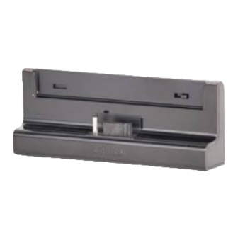
Controls Figure 1 and the section following identify and describe the controls and connectors of the vehicle dock. Figure 1 Figure 1 Lock Switch: Locks and unlocks the SIRIUS radio in the vehicle dock. Mounting Holes: Mounting holes for attaching the suction cup mount or the vent mount. FM OUT Connector: FM output for use with the optional FM Direct Adapter. -
Page 10: Installation
Installation SIRIUS suggests professional installation of this product in your vehicle. Professional instal- lation provides an experienced technician to install this product in your vehicle, advice for se- lecting a suitable mounting location, installation of the antenna, and routing all the necessary wires and cables. - Page 11 Figure 1 Figure 1 Depending upon the mounting location you select in your vehicle, the mount should be at- tached to the vehicle dock and installed as described in the following sections. Installation...
- Page 12 Suction Cup Mount Method (A) The suction cup mount may be attached to any smooth surface. Before attaching the suction cup mount to your windshield, you should check your state and local laws for regulations regarding mounting this device on your windshield. To mount the vehicle dock using the suction cup mount, assemble the mount as follows: Attach the vehicle dock to the suction cup mount using the provided screws.
- Page 13 Be sure the cam lever is up (as shown in Figure 3) and position the suction cup mount on the windshield or other location you which have chosen. Press the cam lever all the way down towards the base of the mount until it locks to adhere the suction cup. (To unlock the suction cup, lift the lever up.) Figure 3 Figure 3...
- Page 14 Vent Mount Method (b) To mount the vehicle dock using the vent mount method, install the vent mount as follows: If the vent louvers in your vehicle are recessed, you may need to use the longer vent hooks with the vent mount. Refer to Figure 4 and install the longer vent hooks into the vent mount.
- Page 15 Refer to Figure 6 and attach the vent mount to a heating/air conditioning vent in your vehicle. Position the two tension springs A against a vent louver B. Then push the vent mount into the vent, far enough so that the hooks C drop down and hook the rear of the vent louver (Figure 7).
-
Page 16: Installing The Antenna
The angle of the vehicle dock may be changed by changing the position of foot D on the vent mount (Figure 6) to a different adjustment hole. (Figure 8) ADJUSTMENT HOLES Figure 8 Figure 8 Installing the Antenna The optimum mounting location for the magnetic antenna is on the roof of the vehicle, with a minimum unobstructed area of 12 inches by 12 inches, and exactly 6½... - Page 17 Figure 9 Figure 9 Sedan/Coupe. Mount the antenna along the rear center-line of the vehicle roof, located at the rear of the roof near the rear window. Pickup Truck. Mount the antenna along the rear center-line of the cab roof, located at the rear of the roof near the rear window.
- Page 18 Connect the rubber antenna cable cover/tail to the antenna cable, making sure that the strain- relief on the antenna sits into the rubber antenna cable cover/tail groove. (Figure 10) Route the antenna cable through the wire channel in the rubber antenna cable cover/tail. Do not remove the protective strips yet.
-
Page 19: Connecting The Cigarette Lighter Adapter
ber antenna cable cover/tail for another 30 seconds. (Figure 12) At room temperature (68 degrees), maximum adhesion usually occurs within 72 hours. During this period, avoid car washes and other contact with the antenna and rubber antenna cable cover/tail. Connect the antenna cable to the AnT connection at the rear of the vehicle dock. (Refer to Figure 1 on page 9 for the location of this connector.) Connecting the Cigarette Lighter Adapter Connect the provided cigarette lighter adapter to the DC5V connection at the rear of the... - Page 20 Figure 13 Figure 13 For SIRIUS radios which do not require the adapter, make sure the lock on the vehicle dock is set in the unlocked position and place the SIRIUS radio into the vehicle dock, pressing the radio down until it is fully seated. Slide the lock into the locked position. (Refer to Figure 1 on page 9 for the location of the lock.) Installation...
-
Page 21: Maximizing Audio Quality From Your Sirius Radio
Maximizing Audio Quality From Your SIRIUS Radio There are two primary ways to connect your SIRIUS radio to your vehicle radio: Wireless Connection or Direct Connection. The following sections will help you obtain the best perfor- mance. For the latest information go to http://www.sirius.com/vehicleinstallation. Wireless CONNeCTiON Your SIRIUS radio contains an FM transmitter. - Page 22 note: The FM transmitter in your SIRIUS radio is automatically set to FM channel 88.1. This may not be the best channel in your area. Tip: If you regularly travel between cities with different active FM channels, you may need to find channels that are not broadcasting in each city. Several SIRIUS radio models can store multiple FM transmit channels, so you can easily switch to the best FM channel for each city.
- Page 23 The FM antennas found in vehicles are of four distinct types: • Aerial Type Fender Mounted FM Antenna: A fixed or retractable aerial antenna located on the front or rear fender of the vehicle. • Aerial Type Roof Mounted FM An- tenna: A fixed aerial antenna mounted on the roof (often at the front or rear of the roof, just above the window glass).
- Page 24 • on Glass Type FM Antenna: Wires on the window glass of the vehicle, usually near the top of the window. It may be located on the windshield glass, the rear window glass, or a rear side window in some SUV and mini-van type vehicles (and other vehicles).
- Page 25 The FM Extender Antenna should be placed inside the vehicle, as close as possible to the vehicle’s FM antenna. A test mounting should be done first using the included suction cup mounts to test the installation. Once an acceptable location has been found, you will remove the suction cups and permanently adhere the FM Extender Antenna using the adhesive mounts.
- Page 26 Alternate mounting location on adjacent A-Pillar Figure 16 Figure 16 Figure 17 Figure 17 Installation...
- Page 27 b Installation Instructions for Vehicles with Aerial Type Roof Mounted FM Antenna For vehicles where the FM radio antenna is located on the front or rear of the roof of the vehicle, the FM Extender Antenna should be mounted horizontally on the front or rear glass below the FM antenna, or installed into the headliner of the vehicle under the FM antenna.
- Page 28 Installation Instructions for Vehicles with on glass Type FM Antenna For vehicles where the FM radio antenna is located on the window glass, the FM Extender Antenna can be mounted horizontally on the glass, directly over the FM radio antenna, or installed into the headliner of the vehicle directly above the FM antenna.
- Page 29 Figure 20 Figure 20 Installation...
- Page 30 d Installation Instructions for Vehicles with Shark Fin Type FM Antenna For vehicles where the FM radio antenna is located on the rear of the roof of the ve- hicle, the FM Extender Antenna should be mounted horizontally on the glass below the FM antenna, or installed into the headliner of the vehicle under the FM antenna.
- Page 31 Plug the FM Extender Antenna into the FM OUT connector of the vehicle dock. (Figure 22) From FM Extender Cable FM OUT Figure 22 Figure 22 Tune your vehicle’s FM radio and your SIRIUS radio to the same FM channel (Figure 23): a.
- Page 32 note: The FM transmitter in your SIRIUS radio is automatically set to FM channel 88.1. This may not be the best channel in your area. Tip: If you regularly travel between cities with different active FM channels, you may need to find channels that are not broadcasting in each city. Several SIRIUS radio models can store multiple FM transmit channels, so you can easily switch to the best FM channel for each city.
- Page 33 DireCT CONNeCTiONs Direct connection provides better audio performance than a wireless connection and removes the possibility of interference from local FM broadcasters. direct Wired Audio Connection If your vehicle radio offers an “AUX IN” or “LINE IN” connection, it is the best audio connec- tion available.
- Page 34 Cassette Adapter If your vehicle radio has a cassette player: Purchase a Cassette Adapter at your local electronics retailer. Connect the adapter between the “AUDIO OUT” or “LINE OUT” on your SIRIUS radio and the vehicle radio’s cassette slot. (Figure 27) TRANSMITTER Figure 27 Figure 27...
- Page 35 SIRIUS FM direct Adapter If your vehicle radio does not have an “AUX IN” or “LINE IN” jack, the SIRIUS FM Direct Adapter provides a wired connection between your SIRIUS radio and your vehicle radio, elimi- nating the outside static and interference you sometimes experience when using a wireless FM connection.
-
Page 36: Subscribing To The Sirius Service
When you have successfully subscribed to the SIRIUS service, and the radio has been updated with your subscription information, an alert will be displayed. To continue, press the Select button. You are now ready to begin enjoying SIRIUS Satellite Radio’s digital entertainment, and can tune to other channels! Installation... -
Page 37: Troubleshooting
Troubleshooting Symptom Solution SIRIUS radio does not Blown fuse, or the Cigarette Lighter Adapter is not properly con- power on nected. Check the Cigarette Lighter adapter connection. Refer to the vehicle’s owners manual for the location of the vehicle’s fuse panel and check for a blown fuse. -
Page 38: Optional Accessories
Optional Accessories The following optional accessories are available for purchase from your SIRIUS retailer to maximize your SIRIUS experience: SUbX1 SIRIUS Plug and Play Universal boombox The SUBX1 SIRIUS Plug and Play Universal Boombox is a portable docking station and audio system for use with the SIRIUS radio. -
Page 39: Warranty
Warranty 12 Month Warranty SIRIUS Satellite Radio Inc. (the “Company”) warrants to the original retail purchaser of this product that should this product or any part thereof, under normal use and conditions, be proven defective in material or workmanship within 12 months from the date of original purchase, such defect(s) will be repaired or replaced with new or reconditioned product (at the Company’s option) without charge for... -
Page 40: Specifications
Specifications Cigarette Lighter Adapter Fuse Requirement ......2A Slow Blow Cigarette Lighter Adapter Cable Length ........1.8m (6ft.) Cigarette Lighter Adapter Operating Temperature . -
Page 41: Sirius Id
SIRIUS ID Write down the SIRIUS ID (SID) of your SIRIUS radio in the space provided below. SID: _______________________________________ SIRIUS ID... - Page 43 SIRIUS Customer Service: 1-888-539-7474 customercare@sirius-radio.com SIRIUS Satellite Radio Inc. 1221 Avenue of the Americas New York, NY 10020 1-888-539-7474 http://www.sirius.com...
- Page 44 SIRIUS Satellite Radio Inc. 1221 Avenue of the Americas New York, NY 10020 (800) 869-5590 http://sirius.com SIRIUS SUPV1-FM Extender Antenna (102406b)
Need help?
Do you have a question about the SUPV1 and is the answer not in the manual?
Questions and answers