Table of Contents
Advertisement
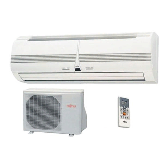
HEAT & COOL MODEL
(REVERSE CYCLE)
ROOM AIR CONDITIONER
WALL MOUNTED TYPE
Indoor Unit
AST7USACW
AST9USACW
AST12USACW
Outdoor Unit
AOT7USAC
AOT9USAC
AOT12USAC
KEEP THIS OPERATION MANUAL
FOR FUTURE REFERENCE
FUJITSU GENERAL LIMITED
OPERATING MANUAL
REFRIGERANT
THIS PRODUCT MUST ONLY BE INSTALLED OR SERVICED
BY QUALIFIED PERSONNEL.
Refer to Commonwealth, State, Territory and local legislation,
regulations, codes, installation & operation manuals, before
the installation, maintenance and/or service of this product.
R410A
This Air Conditioner contains and operates
with refrigerant R410A and Polyol Ester oil.
P/N9312175093-01
Advertisement
Table of Contents

Related Manuals for Fujitsu AST7USACW


Summary of Contents for Fujitsu AST7USACW
-
Page 1: Operating Manual
THIS PRODUCT MUST ONLY BE INSTALLED OR SERVICED BY QUALIFIED PERSONNEL. Refer to Commonwealth, State, Territory and local legislation, regulations, codes, installation & operation manuals, before KEEP THIS OPERATION MANUAL the installation, maintenance and/or service of this product. FOR FUTURE REFERENCE FUJITSU GENERAL LIMITED P/N9312175093-01... -
Page 2: Table Of Contents
CONTENTS SAFETY PRECAUTIONS ........... 1 ADJUSTING THE DIRECTION OF FEATURES AND FUNCTIONS ........2 AIR CIRCULATION ..........10 NAME OF PARTS ............4 SWING OPERATION ..........11 PREPARATION ............5 MANUAL AUTO OPERATION ........ 11 OPERATION .............. 6 CLEANING AND CARE ........... 12 TIMER OPERATION .......... -
Page 3: Features And Functions
FEATURES AND FUNCTIONS AUTO CHANGEOVER REMOVABLE INTAKE GRILLE The operation mode (cooling, heating) is switched automati- The indoor unit’s Intake Grille can be removed for easy clean- cally to maintain the set temperature, and the temperature ing and maintenance. is kept constant at all times. MILDEW-RESISTANT FILTER SLEEP TIMER The AIR FILTER has been treated to resist mildew growth,... - Page 4 Fig. 1 Fig. 2 OPERATION TIMER SWING Fig. 3 Fig. 5 Fig. 4 ª – ⁄ ºŸ £ ∞ § & ¢ ¶ • ™ ¡ ≠ Fig. 6 Fig. 7 This figure shows the control display when all indicator lamps are on. It may differ from the actual display.
-
Page 5: Name Of Parts
NAME OF PARTS Fig. 1 Indoor Unit Fig. 6 Remote Control Unit 1 Operating Control Panel (Fig. 2) J SLEEP button 2 MANUAL AUTO button K MASTER CONTROL button L SET TEMP. buttons ( 3 Remote Control Signal Receiver M Signal Transmitter 4 Indicator Lamps (Fig. -
Page 6: Preparation
PREPARATION CAUTION! Turn on the Power ● Take care to prevent infants from Connect the Power Supply Plug (Fig. 1 C) to an electri- accidentally swallowing batteries. ● When not using the remote control unit cal outlet; in the case of a direct line connection, turn for an extended period, remove the batteries to avoid possible leakage and on the circuit breaker. -
Page 7: Operation
OPERATION To Select Mode Operation Press the START/STOP button (Fig.6 S). The indoor unit’s OPERATION indicator lamp (red) (Fig. 3 5) will light. The air conditioner will start operating. Press the MASTER CONTROL button (Fig.6 K) to se- lect the desired mode. Each time the button is pressed, the mode will change in the following order. - Page 8 OPERATION To Stop Operation Press the START/STOP button. The OPERATION indicator lamp (red) (Fig. 3 5) will go out. About AUTO CHANGEOVER Operation ● When AUTO CHANGEOVER operation first selected, the fan will oper- AUTO: ate at very low speed for about one minute, during which time the unit detects the room conditions and selects the proper operating mode.
-
Page 9: Timer Operation
TIMER OPERATION To Use the OFF TIMER To Cancel the Timer Press the START/STOP button (Fig. 6 S) Press the CANCEL TIMER button. (if the unit is already operating, proceed to step 2). To Change the Timer Settings The Indoor Unit’s OPERATION Indicator Lamp (red) (Fig. 3 5) will light. Press the ON TIMER button/OFF TIMER button as required. -
Page 10: Sleep Timer Operation
SLEEP TIMER OPERATION Unlike other timer functions, the SLEEP timer is used to set the length of time until air conditioner operate is stopped. To Use the SLEEP timer To Cancel the Timer: While the air conditioner is operating or stopped, press the Press the CANCEL TIMER button. -
Page 11: Adjusting The Direction Of Air Circulation
ADJUSTING THE DIRECTION OF AIR CIRCULATION Vertical (up-down) direction of airflow is adjusted by pressing the Remote Control Unit’s AIR FLOW DIRECTION button. Hori- zontal (right-left) airflow direction is adjusted manually, by moving the Air Flow Direction Louvers. Whenever making horizontal airflow adjustments, start air conditioner operation and be sure that the vertical air direction louvers are stopped. -
Page 12: Swing Operation
SWING OPERATION Begin air conditioner operation before performing this procedure. To select SWING Operation Press the SWING LOUVER button (Fig. 6 U). The SWING indicator lamp (orange) (Fig. 3 7) will light. In this mode, the Air Flow Direction Louvers will swing automatically to direct the air flow both up and down. -
Page 13: Cleaning And Care
CLEANING AND CARE ● Before cleaning the air conditioner, be sure to turn it off and disconnect the Power Supply Cord. CAUTION! ● Be sure the Intake Grille (Fig. 1 8) is installed securely. ● When removing and replacing the air filters, be sure not to touch the heat exchanger, as personal injury may result. -
Page 14: Troubleshooting
TROUBLESHOOTING In the event of a malfunction (burning smell, etc.), immediately stop operation, disconnect the WARNING! Power Supply Plug, and consult authorized service personnel. Merely turning off the unit’s power switch will not completely disconnect the unit from the power source. Always be sure to disconnect the Power Supply Plug or turn off your circuit breaker to ensure that power is completely off. -
Page 15: Operating Tips
TROUBLESHOOTING Symptom Items to check See Page ● Is the Power Supply Plug disconnected its outlet? CHECK ONCE Doesn’t operate at all: MORE ● Has there been a power failure? — ● Has a fuse blown out, or a circuit breaker been tripped? ●... -
Page 16: Temperature And Humidity Range
OPERATING TIPS Temperature and Humidity Range Cooling Mode Dry Mode Heating Mode Outdoor temperature About 21-43 °C About –5-24 °C About 21-43 °C Indoor temperature About 18-32 °C About 18-32 °C About 27 °C or less ● If the air conditioner is used under higher temperature conditioner than those listed, the built-in protection circuit may operate to prevent internal circuit damage.
Need help?
Do you have a question about the AST7USACW and is the answer not in the manual?
Questions and answers