
Subscribe to Our Youtube Channel
Related Manuals for Beta Three C2402


Summary of Contents for Beta Three C2402
- Page 1 User Manual Beta three C2402 DIGITAL SPEAKER CONTROLLER PARA SET ED-B3-MA-070411-001...
-
Page 2: Table Of Contents
TABLE OF CONTENTS CAUTION INTRODUCTION 2.1 Audio Features 2.2 User Interface 2.3 Other Character UNPACKING AC POWER REQUIREMENTS FRONT PANEL CONTROL FEATURES 6. INTERCONNECT FEATURES .DISPLAYS AND OPERATION 7.1 Gain 7.2 Source 7.3 Polarity 7.4 Peq 7.5 Crossover 7.6 Limit 7.7 Delay 7.8 Mute 7.9 Copy... -
Page 3: Caution
1. CAUTION Instruction: The lightning flash with arrowhead symbol within the equilateral; triangle is intended to alert the user to the presence of un-insulated angerous voltage within the product's enclosure that may be of sufficient magnitude to constitute a risk of electric shock. The exclamation point within the equilateral triangle is intended to alert the user to the presence of important operation an maintenance (servicing) instructions in the literature accompanying this appliance. -
Page 4: Introduction
2.1 Audio Features C2402 get the sample at 48Khz,the distinguish rate is the famous 24's - A/D and D/A switch technology, messenger's handling take the high capability 32 DSP and filter. The digital processor include the gain controller, polarity, PEQ(peak, slope, limit and band pass),delay, crossover(the types are Butter worth/Bessel/Linkwitz, the slope rate are 12dB-36dB) limit. -
Page 5: Front Panel Control Features
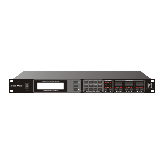
5. FRONT PANEL CONTROL FEATURES PARA SET 1.Power switch: put the 1 means open and 0 means close 2.LCD display: display the operate situation, e.g. the channel's module's set for the digit 3.Parameter set: choose the parameter need to be adjusted and set the +/- key when the Para Is more than two 4.Function key and assistant key on the module: Gain: input/output channel signal gain control... -
Page 6: Interconnect Features
6. INTERCONNECT FEATURES INPUTS OUTPUTS 220V-240V,50Hz/60Hz LINK-OUT RIGHT LINK-OUT LEFT RIGHT LEFT RIGHT LEFT RIGHT HIGH LEFT 1. L(Left) channel audio input socket and link-out socket 2. R(Right) channel audio input socket and link-out socket 3. L/R channel high, mid, low frequency signal output, total 6chs, usually config as 3XCrossOver of stereo 4. -
Page 7: Displays And Operation
7. DISPLAYS AND OPERATION Power on the device and it will display the current Program number and name like following picture: 7.1 Gain Press the Gain key and enter into the gain control interface like the picture: Input and output gain can be adjusted separately, the range is -40db,+12db,the precise is 0.5dB. Input chanelLeft Gain-40~+12dB Press the channel choose key and choose the related channel need to be adjusted, put the +/-... -
Page 8: Peq
7. DISPLAYS AND OPERATION 7.4 PEQ Press the EQ key to enter into the adjust interface of output PEQ as the below picture: First EQ point1 Filter genre Output channel-low Gain Q value Gain -10.5dB EQ center frequency Press the channel choose key and choose the related channel need to be adjusted and press the Para key to choose the parameter which can be changed by the key of +/--. -
Page 9: Limit
7. DISPLAYS AND OPERATION 7.6 Limitations When pressing Limit button, you will enter the adjusted screen of limitation function of output signal, see the following: Output channel-low value of door limit Ratio of compression time of release time of startup Press channel, choose corresponding adjustable channel, and press Para button and then choose parameter, +/- to change the parameter value. -
Page 10: Copy
7. DISPLAYS AND OPERATION 7.9 Copy Press copy and enter the screen of parameter copy, and then copy the present parameter to another channel, see the following: Choose the present choose parameter channel Choose the aim channel automatically Press the choosing channel to choose the present channel,(the aim channel will choose another channel in one group) ,press +/-to choose the copy parameter ,after choosing, repress copy button to confirm the copy one. -
Page 11: Other Tools
7. DISPLAYS AND OPERATION 7.12 Other Tooling Press utility to enter the setting screen of assistant function, we can set the plate lock and contrast, see the following: Switch of system lock LCD contrast Press Para to choose LCD contrast, and press +/- to adjust contrast, we can choose 00(weak), 01(normal), 02(strong). -
Page 12: Troubleshooting
8. TROUBLESHOOTING Problem Check And Solution Whether power cable connect to power supply net, Cannot POWER ON or the switch not press down Parts of key on panel Key lock function enable or not? cannot operation Whether input, output are in the condition of mute? Whether input, output gain decay overabundance? No signal output or is Whether input, output signal route is correct? -
Page 13: Specifications
9. SPECIFICATIONS Analog Input: Input: balance XLR-3-32 input socket Input Impedance: 10k Max input level: +20dBu A/D Convertor: 48kHz sample frequency, 24bits linear Analog Output: Input: balance XLR-3-32 out put socket Output Impedance: 100 Load impedance: Max input level: +20dBu Simulation Sound: Frequency response: 20Hz~20 kHz (+0.3/-0.3dB), 10Hz~30kHz (+0.3/-3.0dB) Dynamic range: 110dB(A -Weight) -
Page 14: Block Diagram
10.BLOCK DIAGRAM INPUT OUTPUT Source: Delay HPF+LPF Left Gain Delay Mute Gain Limit Mute Left HIGH Left Right Delay HPF+LPF Limit Mute Gain Right Right Gain Delay Mute Delay HPF+LPF Gain Limit Mute Left Left+Right Right Delay HPF+LPF Gain Limit Mute Only LOW output may be selected source Input 4EQs,Output 6EQs&HPF+LPF...
Need help?
Do you have a question about the C2402 and is the answer not in the manual?
Questions and answers