
Related Manuals for Valet VBC Plus


Summary of Contents for Valet VBC Plus
-
Page 1: Installation Guide
Valet Video Intercom VBC Plus System Installation Guide User Guide PLEASE READ AND UNDERSTAND THIS MANUAL BEFORE INSTALLING AND OPERATING... -
Page 2: Table Of Contents
Video Intercom System Contents PAGE 1. Intercom Monitor and Handset 2. Doorbell/Camera 3. Instalment method and wiring diagrams 4. Operation Instructions 5. Technical Specifi cations 6. Notes... -
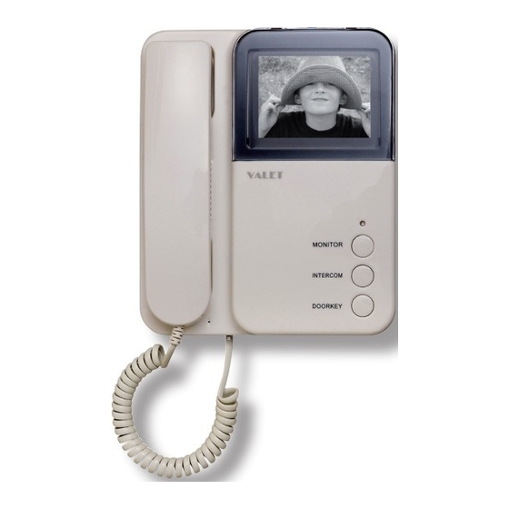
Page 3: Intercom Monitor And Handset
1. INTERCOM MONITOR AND HANDSET VOLUME RING VOLUME ADJUST JS-VP JS-AP JP-VD JP-LK DC IN 220mm (h) x 190mm (w) x 55mm (d) Screen 11. Ringing volume Indicator 12. JS-VP port for Back Bracket Board Monitor button 13. Not Used Intercom button 14. -
Page 4: Doorbell/Camera
2. DOOR BELL/CAMERA 1. Camera 2. Speaker 3. Call button 4. Microphone 5. Connecting Terminal 6. Terminal for door-release 7. Back Board 8. Access Bracket 128(h )x 98(w) x 43(d) 3. ACCESSORIES Power supply adapter Instalment screws: M4 5pc Doorbell Camera Bracket M6 1pc Monitor Mounting Bracket... -
Page 5: Instalment Method And Wiring Diagrams
4. MONITOR / HANDSET INSTALLATION Note: An expansion module PCB is required to be fi tted to the main monitor bracket in multiple monitor and/or 2 doorbell camera systems. Installing method: 1) Check Mounting Height (145cm/160cm). 2) Pass doorbell camera and power adapter cable through the rear of the mounting bracket before connection. - Page 6 Weather shields and various face plate accessories are available as optional extras. Please see your Valet Dealer or call 1800 050 333. 1) Chose height of Camera...
- Page 7 6. SINGLE MONITOR CONNECTING AND DIAGRAM Valet recommends that Valet 8 Intercom cable is used in the wiring of its video intercom systems. The Valet 8 cable provides the appropriate screened cable for both video and audio signals. Connecting Cable to the Monitor Mounting Bracket PCB...
- Page 8 7. MULTIPLE MONITOR AND MULTIPLE DOOR BELL SYSTEMS Multiple Monitor Systems When adding monitor/handsets a new expansion PCB must be fi tted to your main monitor mounting bracket. This new PCB allows the single monitor to become a multiple monitor and Doorbell Camera distributor. The expansion PCB allows up to 4 monitors and 2 Doorbell Cameras to be connected as a network system.
- Page 9 8. MULTIPLE MONITOR SYSTEM CONNECTION AND NETWORK DIAGRAM...
-
Page 10: Operation Instructions
9. OPERATION 1. When the visitor presses the “CALL” button on the doorbell/camera, the electronic bell in the monitor/s chime. At the same time, the screen/s display the visitors’ image. 2. You can pick up the phone from any monitor and talk with the visitor for 90 seconds. -
Page 11: Technical Specifi Cations
10. TECHNICAL SPECIFICATIONS Monitor/Handset Display screen 4 inch B/W CRT Resolution >300 TV lines Scan frequency 15,625Hz(H) 50Hz(V) Power voltage DC 15~18V Video input 75 1Vp-p CCIR standard Power consumption Standby state 0.5W; working state 15W Wiring mode 4 wires polar Dimension 185(W) x 230(H) x 60(D) Weight... -
Page 12: Notes
NOTES...
Need help?
Do you have a question about the VBC Plus and is the answer not in the manual?
Questions and answers