Table of Contents
Advertisement
Quick Links
PLEASE KEEP THESE INSTRUCTIONS FOR FUTURE REFERENCE
PELLET STOVE
KINDERHOOK
OWNER'S MANUAL
Contact your building or fire officials about restrictions and installation inspection
requirements in your area.
PLEASE READ THIS ENTIRE MANUAL BEFORE
INSTALLATION AND USE OF THIS PELLET-BURNING ROOM
HEATER. FAILURE TO FOLLOW THESE INSTRUCTIONS
COULD RESULT IN PROPERTY DAMAGE, BODILY INJURY OR
EVEN DEATH.
4001609
*****
THIS MANUAL IS PRINTED ON RECYCLED PAPER.
50-2465
Advertisement
Table of Contents

Related Manuals for Hudson River Kinderhook


Summary of Contents for Hudson River Kinderhook
- Page 1 PLEASE KEEP THESE INSTRUCTIONS FOR FUTURE REFERENCE PELLET STOVE KINDERHOOK OWNER’S MANUAL Contact your building or fire officials about restrictions and installation inspection requirements in your area. PLEASE READ THIS ENTIRE MANUAL BEFORE INSTALLATION AND USE OF THIS PELLET-BURNING ROOM HEATER.
-
Page 2: Table Of Contents
Table of Contents ......................3 introduction ....................3 rating label location ......................3 pellet quality ....................4 important safety data ................4 safety warnings and recommendations & ......................6 dimensions specifications .........................6 dimensions ..................6 s p e c i f i c at i o n s ....................7 i n s ta l lat i o n ..............7... -
Page 3: Introduction
Since Hudson River Stove Works has no control over the quality of pellets that you use, we assume no liability for your choice in wood pellets. -
Page 4: Important Safety Data
To prevent the possibility of a fire, ensure that the appliance is properly installed by adhering to the installation instructions. A HUDSON RIVER dealer will be happy to assist you in obtaining information with regards to your local building codes and installation restrictions. - Page 5 If this power cord should become damaged, a replacement power cord must be purchased from the manufacturer or a qualified HUDSON RIVER dealer. This unit’s maximum power requirement is 400 watts.
-
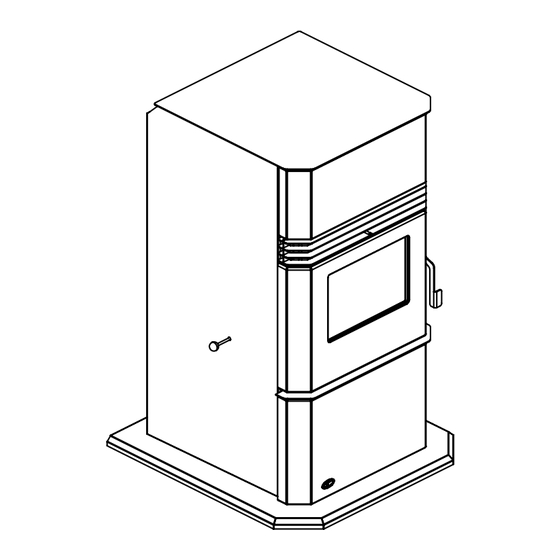
Page 6: Dimensions & Specifications
Specifications imenSionS ReeStanDing 2 " 24" 44" 4 " 4 " Figure 1: Kinderhook Dimensions. PecificationS Input rating: 42,500BTU Table 1: Kinderhook Specifications. Description Fuel type Residential Pellet Heater Voltage Current Max Power 110 - 120 V 3.3 Amps 400 Watts... -
Page 7: Installation
Installation eciDing heRe to ocate youR eLLet PPLiance 1. Check clearances to combustibles (see i nstallation learances to ombustibles , and i nstallation lcove learances nstallation 2. Do not obtain combustion air from an attic, garage or any unventilated space. Combustion air may be obtained from a ventilated crawlspace. 3. -
Page 8: Clearances To Combustibles
6" 9” MINIMUM Figure 5: Minimum Clearances to Combustibles for Freestanding Figure 4: Kinderhook on Floor Protection. Kinderhook. This pellet stove requires floor protection. The floor protection must be non-combustible, extending beneath the stove the full width and depth of the unit including 9“ in front for ember protection. -
Page 9: Mobile Home Installation
Installation obiLe nStaLLation WARNING: Do not install in a room people sleep in. CAUTION: The structural integrity of the manufactured home floor, wall and ceiling/roof must be maintained secure with three (3) screws evenly spaced. Hearth Pad Flooring Steel Frame Ground wire directly "... -
Page 10: Vent Termination Requirements
5. If the unit is incorrectly vented or the air to fuel mixture is out of balance, a slight discoloration of the exterior of the house might occur. Since these factors are beyond the control of Hudson River Stove Works, we grant no guarantee against such incidents. -
Page 11: Exhaust And Fresh Air Intake Locations
21.181 15.462 .996 5.703 12.906 8.199 Figure 9: Kinderhook Inlet and Outlet Location. INSTALL VENT AT CLEARANCES SPECIFIED BY THE VENTING MANUFACTURER utSiDe ReSh onnection Outside fresh air is mandatory when installing this unit in airtight homes and mobile homes. -
Page 12: Corner Through Wall Installation
Installation oRneR hRough nStaLLation Fresh Air Intake 3" (7.5 cm) Wall thimble manufactured by pellet vent manufacturer. 3" (7.5 cm) Figure 12: Corner Installation. oRizontaL xhauSt hRough nStaLLation ReeStanDing Vent installation: install vent at clearances specified by the vent manufacturer. A chimney connector shall not pass through an attic or roof space, closet or similar concealed spaces, or a floor, or ceiling. - Page 13 Installation 10. The pipe must extend least from the building. If necessary, bring another length of Exhaust Tube pipe (PL type) to the outside of the home 3" (75mm) or 4" (100mm) "PL" or "L" vent to connect to the Wall Thimble first section.
-
Page 14: Vertical Rise With Horizontal Termination Installation ( Recommended )
Installation eRticaL iSe With oRizontaL eRmination nStaLLation ecommenDeD Termination cap 90°elbow Wall framing Vertical section of vent pipe in place of the termination cap (or stainless steel Horizontal frame for thimble termination hood). Wall strap Recommended vent size for vertical installation: Clean out tee Wall... -
Page 15: Inside Vertical Installations
Installation nSiDe eRticaL nStaLLationS 1. Choose a stove location that is ideal. See the section “i nstallation eciding here to ocate your ellet ppliance 2. Place unit Rain cap - ensure cap is at hearth pad (if installed on least 2 feet (610mm) above a carpeted surface) and the roof at the lowest point space the unit in a manner... -
Page 16: Outside Vertical Installations
Installation utSiDe eRticaL nStaLLationS To accomplish a outside vertical pipe installation, follow steps 1 through 5 in the “i ” nside ertical nstallations section and then finish it by performing the following (refer to Figure 23). 1. Install a tee with clean out on the outside of the house. 2. -
Page 17: Hearth Mount Installation
Installation eaRth ount nStaLLation Damper Removed or Fastened Open Mantel Rain cap Minimum 8" (20 cm) from top of stove NOTE: Hopper lid will not open fully with less than 23”. Storm collar Clean-out tee Fresh-air intake should Min 9" come from chimney. -
Page 18: Thermostat Installation
Installation heRmoStat nStaLLation 1. Install the wall thermostat in a location that is not to close too the unit but will effectively heat the desired area. 2. Install a 12 or 24 Volt Thermostat using an 18 x 2 gauge wire from the unit to the thermostat. If the unit has been placed in the HI / LOW mode, the unit will be taken to a low or idle setting when the thermostat is not calling for heat. -
Page 19: Operating Instructions
Operating Instructions ontRoL oaRD unctionS 1. AUGER LIGHT: This green light will flash in conjunction with the auger pulse. 2. MODE LIGHT: Responsible for signaling the state of the control board. When the light is flashing the stove is in an automatic start mode or the thermostat has control of the unit. When the light is solid, the Heat Level Setting can be altered. -
Page 20: Turning Your Pellet Stove Off
Operating Instructions AUGER AUGER MANUAL MODE: MODE MODE All control of circuit board function is adjusted at the circuit board. To START: Press the ON / OFF button. The stove will turn on. The AUTO/OFF AUTO/OFF system light will flash. The Auger Light will flash with each pulse of the HIGH/LOW HIGH/LOW MANUAL... -
Page 21: Adjusting The Vacuum Using The Slider Damper
Operating Instructions LiDeR amPeR THE SLIDER / DAMPER MUST BE SET AT TIME OF INSTALLATION. A Qualified Service Technician This is used to regulate the airflow through the pellet stove. The or Installer must set the Slider Damper. slider damper knob is located on the left cab side (see Figure 7). If the fire should happen to go out and the heat output indicator has been set on the lowest setting, the Slider Damper should be pushed in slightly, decreasing the air in the firebox. -
Page 22: Routine Cleaning And Maintenance
Routine Cleaning and Maintenance The following list of components should be inspected and maintained routinely to ensure that the appliance is operating at its optimum and giving you excellent heat value: 2-3 Days / Weekly Semi-annually or 2 Tons of Fuel Burn Pot and Liner Exhaust Vent Ash Pan... -
Page 23: Introduction .............................................................................................................3
ASH PAN AND DOOR GASKETS (weekly) After extended use the gasketing may come loose. To repair this, glue the gasketing on using high- temperature fiberglass gasket glue available from your local HUDSON RIVER dealer. This is important to maintain an airtight assembly. -
Page 24: Routine Cleaning And Maintenance
REPLACING DOOR GLASS It is recommended that your HUDSON RIVER dealer replace the glass if broken. The door glass is made of high temperature PYRO CERAMIC 5 mm thick. Replace only with part# EF-061. -
Page 25: Troubleshooting
Troubleshooting DO NOT: if handled improperly. Only qualified technicians should deal with possible internal electrical failures. WHAT TO DO IF: 1. The stove will not start. 2. The stove will not operate when hot. 3. The exhaust blower will not function normally. 4. - Page 26 Troubleshooting Check Vacuum levels in the exhaust channel by bypassing the Vacuum Switch, then remove the Vacuum hose from Vacuum Switch. Check exhaust vacuum readings by placing the open end of the Vacuum or operational. properly, the unit may require cleaning or a new sensor. Contact your local dealer for service. Check the fuse on the circuit board.
- Page 27 Troubleshooting 6. The 200 °F ( 93 °C) high limit temperature sensor has tripped. replace the blower? If yes, replace sensor (located on the left side of the firewall). Check the fuse on the circuit board. 7. The convection blower will not function normally. Clean all grill openings at the back and below unit .
-
Page 28: Wiring Diagram
Wiring Diagram Grey Vacuum Grey Switch White Combustion Blue Brown Blower Exhaust Temperature Sensor Power Cord Brown Ground Black 115V 115V White Black Black White Thermostat Common 5 Amp Ignitor Fuse Convection Temperature Black Sensor White Orange Orange Purple Purple Convection Blue White... -
Page 29: Parts Diagrams
PARTS DIAGRAMS... - Page 30 PARTS DIAGRAMS...
-
Page 31: Parts List
50-2337 CONTROL PANEL C/W DECAL 50-2342 FIREBOX LINER C/W INSULATION 50-2465 KINDERHOOK OWNERS TECHNICAL MANUAL 50-2466 KINDERHOOK FS HOPPER LID (OLD SERIALIZED PART MUST BE RETURNED) 50-2467 KINDERHOOK DOOR ASSEMBLY COMPLETE 50-2468 KINDERHOOK CABINET SIDE LEFT 50-2469 KINDERHOOKCABINET SIDE RIGHT... - Page 32 PARTS LIST EF-001 AUGER MOTOR 115V (1 RPM) EF-002 CONVECTION BLOWER 115V EF-004 CONVECTION BLOWER IMPELLER EF-006 CONVECTION BLOWER INSULATOR (GASKET) EF-008 COMBUSTION MAIN IMPELLER 1” x 4 1/2” EF-011 COMBUSTION BLOWER MOUNTING GASKET EF-012 COMBUSTION BLOWER HOUSING GASKET(CIRCULAR) EF-013 EF2/3/4/SOLUS/WIN/MER FAN TEMP SENSOR 160F EF-016 HIGH LIMIT TEMP SENSOR 200 MANUAL RESET (ALL PELLET)
-
Page 33: Warranty
Here is how our Warranty works If you have any concerns with your Hudson River product please contact the dealer where you purchased To the Dealer form: Customer information: Name, address and telephone number of purchaser and date of purchase. -
Page 34: Installation Data Sheet
Installation Data Sheet The following information must be recorded by the installer for warranty purposes and future reference. NAME OF OWNER: NAME OF DEALER: _________________________________________ _________________________________________ ADDRESS: ADDRESS: _________________________________________ _________________________________________ _________________________________________ _________________________________________ _________________________________________ _________________________________________ PHONE:___________________________________ PHONE:___________________________________ NAME OF INSTALLER: SERIAL NUMBER:___________________________ _________________________________________ DATE OF PURCHASE: _____________ (dd/mm/yyyy)
Need help?
Do you have a question about the Kinderhook and is the answer not in the manual?
Questions and answers