Table of Contents
Advertisement
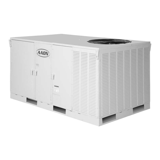
HB
Series
Package Units
& Air Handlers
• R-410A DX or Chilled Water Cooling
• Gas, Electric or Hot Water Heat
• Bottom or Side Discharge
FOR YOUR SAFETY
WHAT TO DO IF YOU SMELL GAS
•
EXTINGUISH ANY OPEN FLAME
•
DO NOT TOUCH ANY ELECTRICAL SWITCH
•
DO NOT TRY TO LIGHT ANY APPLIANCE
•
DO NOT USE ANY PHONE IN YOUR BUILDING
•
IMMEDIATELY CALL YOUR GAS SUPPLIER
FROM A NEIGHBOR'S PHONE. FOLLOW THE
GAS SUPPLIER'S INSTRUCTIONS.
•
IF YOU CANNOT REACH YOUR GAS
SUPPLIER, CALL THE FIRE DEPARTMENT.
Installation and User Manual
FOR YOUR SAFETY
DO NOT STORE OR USE GASOLINE OR OTHER
FLAMMABLE VAPORS AND LIQUIDS IN THE
VICINITY OF THIS OR ANY OTHER APPLIANCE.
WARNING
If the information in this manual is not followed
exactly, a fire or explosion may result causing
property damage, personal injury, or loss of life.
R-410A Package
Air Handler
Advertisement
Table of Contents

Related Manuals for AAON HB Series


Summary of Contents for AAON HB Series
-
Page 1: For Your Safety
Installation and User Manual Series Package Units & Air Handlers • R-410A DX or Chilled Water Cooling • Gas, Electric or Hot Water Heat R-410A Package • Bottom or Side Discharge FOR YOUR SAFETY WHAT TO DO IF YOU SMELL GAS •... -
Page 2: Table Of Contents
Owner should pay particular attention to the words: NOTE, CAUTION, and WARNING. NOTES are intended to clarify or make the installation easier. CAUTIONS are given to prevent equipment damage. WARNINGS are given to alert owner that personal injury and/or equipment damage may result if installation Contents is not handled properly. -
Page 3: Description
OPERATION, multiple power supplies. MAINTENANCE OF EQUIPMENT DESCRIBED IN THIS MANUAL. HB series package units are designed for safe operation when installed, operated, and maintained WARNING within design specifications, and the instructions set forth in this manual. It is necessary to follow these... -
Page 4: Package Unit Orientation
Package Unit Orientation (Compressorized) Service access is from the front of the unit. As you face the front of the unit, the condensing section will be on the right end of the unit, and the air handling section on the left. The drain connection is located on the back. -
Page 5: Air Handling Unit Orientation
Air Handling Unit Orientation (Non-Compressorized) Service access is from the front of the unit. As you face the front of the unit, the controls section will be on the right end of the unit, and the air handling section on the left. The drain connection is located on the back. -
Page 6: Model Number Description
2. Model Number Description Unit Model Number Main Features Discharge Model Nom. Tons Voltage Cooling Heating Location Nominal Tons 002 = 2 Tons 003 = 3 Tons 004 = 4 Tons 005 = 5 Tons Voltage 460V/3∅/60HZ Type* 208-230V/1∅/60HZ 208-230V/3∅/60HZ No Heat Electric Heat Natural Gas Aluminized... -
Page 7: User's Information
air temperatures (typically air temperatures below 3. User’s Information 40°F) that could cause coils to freeze. WARNING Figure 7a, Piping Chase Location Shipping Failure to observe the following instructions may Utility Entry Bracket Piping Chase result in premature failure of your system, and 4”... -
Page 8: Multiple Unit Operation
Normal Thermostat Operation Gas heating units use AAON’s patented high efficiency twisted tube, or dimpled heat exchanger. All heating For Heating system and related safety controls are 100% tested on each unit prior to shipment. -
Page 9: Filter Sizes
Modulating Hot Gas Reheat and Hot Gas Filter Sizes Bypass Systems on DX Units Table 9.1, Pleated Filter Sizes Some DX cooling units may contain Modulating Hot Gas Reheat (MHGRH) and/or Hot Gas Bypass (HGBP) systems as factory installed options. Piping All 2-5 Ton HB Packaged Units and valves for these systems will be located on the inside wall of the condenser section. -
Page 10: Delivery
Contact AAON Warranty Department Handling assistance with handling damaged goods, repairs, and freight claims: 918-583-2266. Be aware of what is contained in the equipment! -
Page 11: Heating And Cooling Systems
warranty. Attach all service panels, and cover all ELECTRIC HEATING SYSTEM exposed equipment when work is not being performed. Leave unit protected from other construction until start- Heating is accomplished by passing electrical current up is to occur. through a specified amount of resistance heaters that produce the required heat. -
Page 12: Service & Installation Clearances
Service & Installation Clearances Figure 12b, Airflow Clearance Minimums Before setting the unit into place, caution must be taken to provide clearance for unit panels/doors that must be accessible for periodic service. These areas contain the controls, safety devices, refrigerant, shut- off valves and filter access. -
Page 13: Setting The Unit
Setting the Unit NOTE Units should always be installed level, and above water drainage routes. Unit operation can be affected PRIOR TO SETTING UNIT ON CURB – To ensure by wind. It is good practice to position unit condensing proper isolation and seal between the unit and the sections away from prevailing winds. -
Page 14: Electrical
If the supply or warm air duct passes through a furnished by AAON. combustible roof, a clearance of one inch must be maintained between the outside edges of the duct... -
Page 15: Optional Control Board
Figure 15a, Power and Control Wiring Compressor and Control Compartment Standard Control Board Red, yellow and green LEDs for fault, mode, and power indicators. Standard Control Board has low voltage terminals for R, G, Y1, Y2, W1, W2, W3 & GND. GND is the ground, or “C”... -
Page 16: Thermostat
Table 16.2, Optional Control Board Blink Codes Each HB has a standard Cooling Lock-out feature that prevents the compressor cooling mode when the Optional Control Board Blink Codes outdoor temperature is below 55°F. Each unit also has a condenser fan cycle feature that delays the start Red LED of the condenser fan until there is satisfactory Fault Condition... -
Page 17: Economizer Option
Thermostat calls for cooling, the bypass damper air. The economizer controller can be field installed or will close and the fan will operate at high speed until factory installed by AAON as selected by the the thermostat is satisfied. customer. - Page 18 Figure 18a, External Control Inputs to Control Board...
-
Page 19: Modulating Hot Gas Reheat
0 Volts to 10 Volts. the occupied space. The humidistat may be purchased from AAON or from others. The thermostat Note: It is possible to create a “reverse acting” control wiring to the control board with single or multi-stages sequence. - Page 20 Figure 20a, Reheated Supply Air Temperature...
-
Page 21: Gas Piping
Gas Piping Table 21.2, Gas Piping Support Intervals Size gas piping to supply the unit with 6” to 10.5” water Pipe Size (In.) Intervals (Ft.) column (w.g.) pressure for natural gas, or 11” w.g. for 3/4 or 1 (horizontal or vertical) propane (when a natural gas to propane conversion kit 1 1/4 or larger (horizontal) has been field installed) when all gas consuming... - Page 22 Figure 22a, Gas Piping Gas Valve Valve Inlet Piping to gas valve inlet must be completed in field. Gas valve installed at factory. Sidewall Entry Bottom or Side Utility Entry Options Run piping through utility entry in front of unit, or through entry in floor of unit located next to the compressor.
-
Page 23: Condensate Piping
Condensate Piping 6. Start-Up HB package units are equipped with a condensate General drain connection, and ‘P’ traps are furnished with the equipment. The drain connection must be used and ONLY QUALIFIED, AUTHORIZED PERSONNEL individually trapped to ensure a minimum amount of SHOULD POWER START-UP... - Page 24 excessive sound, or vibration. Follow procedures DX Cooling: outlined below to start each piece of equipment. Before powering on, or starting the unit: 1. Ensure that drain P-trap is installed. 2. Turn the unit power on. 1. Check the unit for external damage. 3.
-
Page 25: Air Balancing
Electric Heating: Water Balancing 1. Turn the unit power on. A hydronic specialist with a complete working 2. Turn the unit blower on, and check for correct knowledge of water systems, controls, and operation rotation. must be employed to properly balance the entire 3. -
Page 26: Operation & Maintenance
costs during the year. As a minimum, clean the 7. Operation & Maintenance condenser coil at the beginning of each cooling season. It is preferable to use a medium pressure General water spray from the inside of the condenser cabinet with a non-corrosive coil cleaning solution. -
Page 27: Heating Sequence
The service tech may call the factory if assistance is required. BEFORE CALLING, THE MODEL AND SERIAL NUMBER OF THE UNIT WILL BE NEEDED FOR THE WARRANTY SERVICE DEPARTMENT TO HELP ANSWER QUESTIONS REGARDING THE UNIT. AAON Warranty Department: 918-583-2266... -
Page 28: Hot Gas Bypass (External)
0 to 10 VDC signal from another control system. liquid slugging during periods of low airflow operation, or with low entering air temperatures. Figure 28a, AAON’s Modulating Reheat System HGBP is useful when the air conditioning system is subject to variations in load caused by varying air volume or large proportions of outside air. -
Page 31: Pressure-Temperature Chart
Pressure – Temperature Chart R-410A ° ° ° ° ° PSIG PSIG PSIG PSIG PSIG 78.3 142.2 234.9 364.1 540.1 80.0 144.8 238.6 369.1 547.0 81.8 147.4 242.3 374.2 553.9 83.6 150.1 246.0 379.4 560.9 85.4 152.8 249.8 384.6 567.9 87.2 155.5 253.7... - Page 32 It is the intent of AAON to provide accurate and current specification information. However, in the interest of product improvement, AAON, Inc. reserves the right to change pricing, specifications, and/or design of its products without notice, obligation, or liability.
Need help?
Do you have a question about the HB Series and is the answer not in the manual?
Questions and answers