Table of Contents
Advertisement
AAON
HEATING • COOLING & COMBINATION
INSTALLATION, SERVICE
OWNERS INFORMATION MANUAL
!
WARNING
If the information in this manual is not followed
exactly, a fire or explosion may result causing
property damage, personal injury or loss of life.
FOR YOUR SAFETY
DO NOT STORE OR USE GASOLINE OR OTHER
FLAMMABLE VAPORS AND LIQUIDS IN THE
VICINITY OF THIS OR ANY OTHER APPLIANCE.
®
&
1
RL SERIES
ROOFTOP UNITS
FOR YOUR SAFETY
WHAT TO DO IF YOU SMELL GAS
• EXTINGUISH ANY OPEN FLAME.
• DO NOT TOUCH ANY ELECTRICAL SWITCH.
• DO NOT TRY TO LIGHT ANY APPLIANCE.
• DO NOT USE ANY PHONE IN YOUR BUILDING.
• IMMEDIATELY CALL YOUR GAS SUPPLIER FROM A
NEIGHBOR'S PHONE. FOLLOW THE GAS SUPPLIER'S
INSTRUCTIONS.
• IF YOU CANNOT REACH YOUR GAS SUPPLIER,
CALL THE FIRE DEPARTMENT.
Advertisement
Table of Contents

Related Manuals for AAON RL Series


Summary of Contents for AAON RL Series
- Page 1 ® AAON RL SERIES HEATING • COOLING & COMBINATION ROOFTOP UNITS INSTALLATION, SERVICE & OWNERS INFORMATION MANUAL FOR YOUR SAFETY WARNING WHAT TO DO IF YOU SMELL GAS If the information in this manual is not followed • EXTINGUISH ANY OPEN FLAME.
-
Page 2: Table Of Contents
It is the intent of AAON, Inc. to provide accurate and current specification information. However, in the interest of product improvement, AAON, Inc. reserves the right to change pricing, specifications and/or design of it's products without notice, obligation or liablity. -
Page 3: General Description
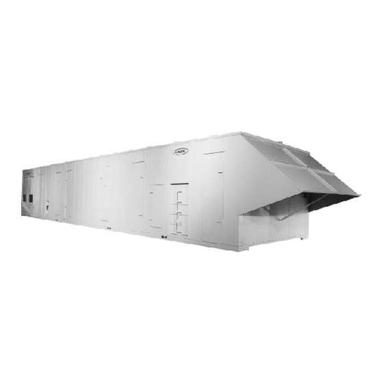
GENERAL DESCRIPTION The units are designed as self-contained heating, cooling or combination units for outdoor or indoor installation WARNING using the refrigerant shown on the rating plate, chilled water, natural gas, electric resistance, steam or hot Improper installation, adjustment, alteration, water. -
Page 4: Owner's Information
OWNER'S INFORMATION Improper installation, adjustment, alteration, service or WARNING maintenance can cause property damage, personal in- Failure to observe the following instructions will result jury or loss of life. Installation and service must be in premature failure of your system, and possible voiding performed by a qualified installer, service agency or if gas of the warranty. -
Page 5: Heating / Cooling Systems
HEATING & COOLING SYSTEMS NORMAL OPERATION INSTALLATION IS TO BE ADJUSTED TO OBTAIN AN AIR TEMPERATURE RISE HEATING WITHIN THE RANGE SPECIFIED ON THE Set the thermostat system switch to "HEAT". RATING PLATE. Set the thermostat fan switch to "AUTO" or "ON". Set the thermostat temperature at the desired point. -
Page 6: Installation
INSTALLATION AAON rooftop units are designed for fast, easy installa- NOTE: Some applications may require the unit to be built and shipped in two seperate sections. tion. The curb is mounted first and must be located so See "Unit Section Splicing" instructions page for more that duct connections will be clear of structural mem- information. -
Page 7: Unit / Curb Detail
INSTALLATION continued CAUTION WARNING Where the supply or warm air duct passes INSULATION MATERIALS MAY through a combustible roof, a clearance BE COMBUSTIBLE of one inch must be maintained between the outside edges of the duct and combustible material in accordance with National Fire Protection Association Standard No. -
Page 8: Unit Section Splicing
INSTALLATION continued Unit Section Splicing AAON ‘RL’ units are designed and built according to unit During the splicing process it is equally important to size and / or job specifications. Some applications may check the alignment of the roof and the connecting require the unit to be built and shipped in two separate flange. -
Page 9: D & E Unit End Flashing Installation
Check the unit data plate voltage to make sure it agrees with the power supply. Connect power to the unit On AAON ‘RL’ (142” wide - D & E cabinet units) the according to the wiring diagram provided with the unit. cabinet width will overhang the trailer on each side. -
Page 10: Compressor Compartment Exhaust Fan - Rain Hood Installation Electrical Information Gas Piping Information
INSTALLATION continued GAS PIPING The furnace must be isolated by closing the manual shut Size gas piping to supply the unit with 6" to 10.5" water off valve or disconnected from the gas supply piping column pressure for natural gas or 11" water column during pressure testing of the piping system with pres- sures in excess of 1/2 PSIG. -
Page 11: Gas Fired Heating Units - Rain Hood Installation
INSTALLATION continued GAS FIRED HEATING UNITS - RAIN HOOD INSTALLATION AFTER UNIT INSTALLATION & BEFORE UNIT STARTUP / OPERATION: Gas fired heating units will have exterior rain hoods shipped with them. They are fastened in place with sheet metal screws. See the photos of the hoods on the exterior of the unit. Notice that higher heating capacity units will have two banks of the gas-fired heat exchangers shown. -
Page 12: Gas Unit Lighting Instructions
INSTALLATION continued GAS UNIT LIGHTING INSTRUCTIONS FOR YOUR SAFETY READ BEFORE OPERATING WARNING: IF YOU DO NOT FOLLOW THESE INSTRUCTIONS EXACTLY, A FIRE OR EXPLOSION MAY RESULT CAUSING PROPERTY DAMAGE, PERSONAL INJURY OR LOSS OF LIFE. This appliance does not have a pilot. It is equipped with an •... -
Page 13: Startup Information
OFF at disconnect switch(es). Unit may have multiple power supplies. Spring Isolator Adjustment START-UP TECHNICIAN MUST CHECK MOTOR AAON ‘RL’ units are equipped with spring isolators in AMPERAGE TO ENSURE THAT THE AMPERAGE the blower section for vibration attenuation. LISTED ON THE MOTOR NAMEPLATE IS NOT Prior to unit shipment the isolators are set in the lock EXCEEDED. -
Page 14: Supply Air Wheel
SHUT OFF all electrical power to the unit to avoid injury from rotating parts. Supply Air Wheel AAON units are equipped with a Backward Inclined ALL TABS Blower Wheel that is set to deliver the air volume speci- MUST BE fied according to unit size and/or job requirements. -
Page 15: Axial Flow Fans
STARTUP continued Axial Flow Fans STEP 4 - Determine Groove Number: 1 or 2 or 3 or 4 Blade Pitch Angle - Degrees Multi-Wing Z Series Fans Rotation Type 20° 27.5 32.5 37.5 Blade Pitch Angle Setting Instructions - - - - - - - - - - - -... -
Page 16: Periodic Inspections
It is recommended that if the gas burners require cleaning, NOTE: The evaporator blower is controlled by the call an AAON Service Engineer at (918) 583-2266. ignition system. In the fan "Auto" mode the blower comes on 45 seconds after flame is proved and goes off HEAT EXCHANGER 120 seconds after the thermostat opens. -
Page 17: Heating - Electric, Steam, Hot Water
PERIODIC INSPECTIONS Continued HEATING • ELECTRIC CONDENSATE PIPING Set thermostat in the heat mode. The RL equipment is furnished with 2 drain connections one on each side of the unit. All drain connections must Set thermostat to call for heat to engage all be used and individually trapped to ensure a minimum electric heat strips. -
Page 18: Service & Maintenance
Non-compliance could result in injury or violation of EPA regulations REFRIGERANT CHARGE All AAON 'RL' units are fully charged at the factory with the refrigerant listed on the rating plate. If additional refrigerant charging should become neces- sary the it should be done at constant load condition. -
Page 19: Lubrication
Evaporator coil(s) should be inspected and cleaned an- nually to ensure there is no obstruction to air flow. ROOFTOP UNIT REPLACEMENT PARTS Replacement parts for AAON equipment may be ob- Condenser coil(s) should be inspected monthly. Clean tained from AAON. When ordering parts, always refer-... -
Page 20: Filter Istallation / Replacement
FILTER INSTALLATION / REPLACEMENT Open filter access door. Slide filters towards you and inspect. Replace old filters with the size indicated on each filter or as shown in the filter chart below. Be sure arrow points towards the blower. (Filters should be checked every 30 days and replaced or cleaned as necessary). IT IS IMPORTANT TO KEEP COILS, BLOWER AND FILTERS CLEAN ! NOTE: CHART REFLECTS STANDARD FACTORY SUPPLIED FILTERS AND SIZES. -
Page 21: Evaporative Condenser Section
EVAPORATIVE CONDENSER SECTION • OPERATION & MAINTENANCE INFORMATION & MAINTENANCE Evaporative cooling equipment rejects heat by evaporat- NEVER DO THIS ing a portion of the recirculated water spray and dis- charging it from the unit with the hot, saturated air. As Building Air the spray water evaporates, it leaves behind the mineral Intake... - Page 22 Condenser Tube Inspection - The coil is leak tested at gauges for proper operation. 350 P.S.I.G. before shipment. AAON will not be respon- Turn rotating element by hand to assure that it sible for loss of refrigerant. It is the responsibility of the rotates freely.
- Page 23 The AAON evaporative condenser is equipped with a desuperheater. The desuperheater coil is located above the eliminators. Approximately 22% of the total heat of rejection is accomplished with the desuperheater.
- Page 24 PARTS Following are important signs to look for when inspecting a given unit: Contact your local AAON Representative for factory 1. Scale formation on the heat exchanger surfaces with authorized parts. Be sure to include the Serial Number from the product nameplate when ordering or request- resulting decreased operating efficiency of ing quotations.
-
Page 25: Trouble Shooting
SERVICING TROUBLE POSSIBLE CAUSE ELECTRIC HEATING 1. Check power at line side of contactor(s). SYSTEM OFF 2. Thermostat not set for heating. 1. Overload relay tripped. 2. Heater Relay not energized. EVAPORATOR MOTOR WILL NOT RUN 3. Blower Contactor not energized. 4. - Page 26 SERVICING Continued TROUBLE POSSIBLE CAUSE STEAM AND HOT WATER HEATING 1. Check power at line side of contactor(s). SYSTEM OFF 2. Thermostat not set for heating. 1. Overload relay tripped. BLOWER MOTOR WILL NOT RUN 2. Heater Relay not energized. 3.
- Page 27 COOLING unit to determine if adequate water is flowing. ROOFTOP UNIT REPLACEMENT PARTS Replacement parts for AAON equipment may be obtained from AAON. When ordering parts, always reference the unit model number, serial number and part number. AAON, Inc. Customer Service Department 2425 South Yukon Ave •...
-
Page 28: Sequence Of Operations
SEQUENCE OF OPERATIONS GENERAL INFORMATION HEATING COOLING Natural Gas Packaged Units When the thermostat calls for heating, W1 makes R to When the thermostat calls for cooling from the space, 'Y1' the heat relay (HR) all N.O. (Normally open) contacts makes 'R' to 'CC1' through the LPS (low pressure switch), close and all N.C. - Page 29 SEQUENCE OF OPERATIONS Continued VAV (Variable Air Volume) SYSTEMS POWER EXHAUST w/ FULL MODULATING ECON. When a call for cooling is received, the controller board In the unit "OFF" or in the minimum economizer posi- stages on compressors to maintain a field set supply air tion, the power exhaust is off.
-
Page 30: Compressor Checkout Procedure
COMPRESSOR CHECKOUT PROCEDURE CONTROL PANEL NOT SET FOR COOLING THERMOSTAT NOT CALLING FOR COOLING CHECK UNIT FUSES POWER TO AND WINDING UNIT LO PRESSURE SWITCH OPEN NO POWER TO HI PRESSURE SWITCH OPEN CONTACTOR NO POWER TO CHECK CIRCUIT BREAKER AT COMPRESSOR LOW AMBIENT LOCKOUT OPEN UNIT POWER DISTRIBUTION PANEL... -
Page 31: Ignition Control Checkout Procedure
IGNITION CONTROL CHECKOUT PROCEDURE CHECK GAS SUPPLY FOR OBSTRUCTIONS OR CLOSED VALVES IS GAS PRESSURE PER MANUFACTURE'S SPECIFICATIONS ? IS SPARK GAP LOCATED IN GAS STREAM ? SPARK IS PRESENT CHECK GAS VALVE WIRING FOR PROPER, BUT BURNER TIGHT CONNECTIONS WILL NOT LIGHT CORRECTION NECESSARY REPLACE CABLE... -
Page 32: Notes / Comments
NOTES / COMMENTS... -
Page 33: Factory Start-Up Form
AAON RL START-UP FORM • Page 1 of 2 ® DATE: JOB NAME: ADDRESS: MODEL No: CITY, STATE: SERIAL No: START-UP CONTRACTOR: TAG: UNIT CONFIGURATION AIR COOLED EVAP. COOLED NO WATER LEAKS CONDENSER SAFETY CHECK START-UP CHECK LIST • GENERAL CHECKS... - Page 34 RL START-UP FORM • Page 2 of 2 AAON ® DATE: JOB NAME: MODEL No: SERIAL No: POWER EXHAUST / RETURN ASSEMBLY ALIGNMENT CHECK ROTATION NAMEPLATE AMPS ___________ MOTOR MAKE & AMPS 3 Ø 3 Ø MOTOR MAKE & AMPS...
- Page 35 SPREADER BARS A B C 100” Wide Cabinet = 112” 192” Minimum Length 192” Minimum Length 142” Wide Cabinet = 154” Equal on Both Legs Equal on Both Legs General Configuration Lift Slot Locations Are Unit Specific NOTE: UNIT MUST BE RIGGED AT ALL MARKED LIFTING POINTS. RL UNIT LIFTING DETAIL Drawing N.T.S...
- Page 36 RL SERIES ® AAON INSTALLATION, SERVICE & OWNERS INFORMATION MANUAL AAON, Inc. 2425 South Yukon Tulsa, Oklahoma 74107 ph: (918) 583-2266 • fax: (918) 583-6094 R10090 (10-02)
Need help?
Do you have a question about the RL Series and is the answer not in the manual?
Questions and answers