Advertisement
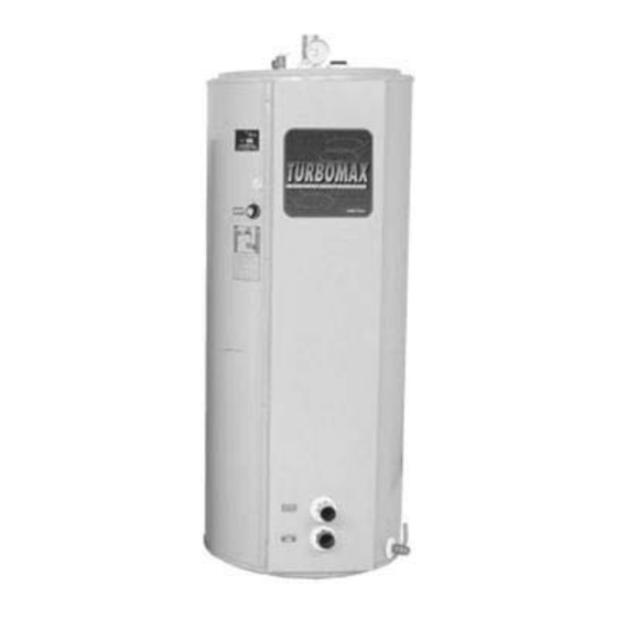
TURBOMAX
Instantaneous Indirect Water Heater
USE & CARE MANUAL
WITH INSTALLATION INSTRUCTIONS FOR THE CONTRACTOR
Your TURBOMAX
factory tested to provide years of trouble-free service. In order to insure the service
intended, the following information is provided to enable proper installation, operation, safety
precautions and maintenance of this product.
It is imperative that all persons who are expected to install, operate or adjust this water
heater read the instructions carefully so that they may understand how to do so.
Any questions regarding the operation, maintenance, service or warranty of this water
heater should be directed to the entity from whom it was purchased. If additional
information is required, refer to the section How to Obtain Service Assistance
When all installation steps have been completed, replace this installation manual in its
original envelope, and keep in a safe place for future reference.
THERMO 2000 INCORPORATED
®
Instantaneous Indirect Water Heater has been carefully assembled and
®
Revision : December 2005
Advertisement
Table of Contents

Related Manuals for THERMO 2000 THERMO 2000


Summary of Contents for THERMO 2000 THERMO 2000
- Page 1 How to Obtain Service Assistance When all installation steps have been completed, replace this installation manual in its original envelope, and keep in a safe place for future reference. Revision : December 2005 THERMO 2000 INCORPORATED...
-
Page 2: Specifications
150 lbs Note: Copyright 2005. Thermo 2000 Inc. All rights reserved. Turbomax® is a registered trademark of Thermo 2000 Inc. Thermo 2000 reserves the right to modify at any time and without notice colors, components, materials, specifications or model described in or shown in this document. -
Page 3: General Safety Precautions
Contact a licensed plumber or local plumbing authority for further information. TURBOMAX Use and Care Manual with Installation Instructions (December 2005) Page... - Page 4 The water heater gets adequate hot water flow from the boiler to maintain the full rated delivery of domestic hot water. TURBOMAX Use and Care Manual with Installation Instructions (December 2005) Page...
- Page 5 1 x thermostatic mixing valve • Switching relays or zone controller • copper pipe & copper pipe fittings • • And any other necessary components. steel pipe & steel pipe fittings TURBOMAX Use and Care Manual with Installation Instructions (December 2005) Page...
-
Page 6: Installation
A check valve should always be installed in the Install shutoff (ball) valves for servicing recirculation line to prevent cold water from convenience. entering. TURBOMAX Use and Care Manual with Installation Instructions (December 2005) Page... - Page 7 5. When a back flow preventer or water meter or a pressure reducing valve is used on the domestic cold water supply line, then a thermal expansion tank must be installed between the water heater and this device. TURBOMAX Use and Care Manual with Installation Instructions (December 2005) Page...
- Page 8 5. When a back flow preventer or water meter or a pressure reducing valve is used on the domestic cold water supply line, then a thermal expansion tank must be installed between the water heater and this device. TURBOMAX Use and Care Manual with Installation Instructions (December 2005) Page...
- Page 9 Prevents siphoning of Use zone valves with low pressure drop the water from the system and collapse of the specifications, particularly on the water heater water heater. zone. TURBOMAX Use and Care Manual with Installation Instructions (December 2005) Page...
- Page 10 The following chart proposes a temperature drop (TD) that should be used to calculate the pump Pump flow rate = 90,000 ÷ 20 ÷ 500 = 9 GPM. flow rate. TURBOMAX Use and Care Manual with Installation Instructions (December 2005) Page...
- Page 11 Tables 1 and 2 provide friction loss values for new pipe. It should be taken into consideration that as the pumping system ages, friction losses increase. It is recommended that for most TURBOMAX Use and Care Manual with Installation Instructions (December 2005) Page...
- Page 12 GPM? Answer: the pressure loss is 2 feet of water. Pressure loss from boiler or other equipment Information on pressure drops (losses) through a boiler or other equipment is obtained from the manufacturer. TURBOMAX Use and Care Manual with Installation Instructions (December 2005) Page...
- Page 13 ASME Boiler and Pressure Vessel Code limits the maximum pressure on the boiler. Since it is a safety TURBOMAX Use and Care Manual with Installation Instructions (December 2005) Page...
- Page 14 Any component, which does not have insulated end switches, must not be used unless a relay is added with the dry contacts wires to these terminals. TURBOMAX Use and Care Manual with Installation Instructions (December 2005) Page...
- Page 15 TURBOMAX Use and Care Manual with Installation Instructions (December 2005) Page...
- Page 16 OWN TEMPERATURE CONTROLLER PUMP ZONE 2 R845A RELAY ZONE 1 THERMOSTAT ZONE 1 PUMP ZONE 1 BOILER THERMOSTAT TERMINAL R845A RELAY TURBOMAX ZONE TURBOMAX AQUASTAT TURBOMAX PUMP PRIORITY RELAY NEUTRAL TURBOMAX Use and Care Manual with Installation Instructions (December 2005) Page...
- Page 17 ZONE 2 OWN TEMPERATURE CONTROLLER PUMP ZONE 2 R845A RELAY ZONE 1 THERMOSTAT ZONE 1 PUMP ZONE 1 BOILER THERMOSTAT TERMINAL R845A RELAY TURBOMAX ZONE TURBOMAX AQUASTAT TURBOMAX PUMP NEUTRAL TURBOMAX Use and Care Manual with Installation Instructions (December 2005) Page...
- Page 18 TURBOMAX Use and Care Manual with Installation Instructions (December 2005) Page...
-
Page 19: Steam Installation
Boiler water in the piping system and in the further information. ® TURBOMAX tank will not flow back into the TURBOMAX Use and Care Manual with Installation Instructions (December 2005) Page... - Page 20 When a back flow preventer or water meter or a pressure reducing valve is used on the domestic cold water supply line, then a thermal expansion tank must be installed between the water heater and this device. TURBOMAX Use and Care Manual with Installation Instructions (December 2005) Page...
- Page 21 TURBOMAX Use and Care Manual with Installation Instructions (December 2005) Page...
-
Page 22: Operation
To let the air out of the TURBOMAX tank during local plumbing authority for further the fill process open the relief valve on top of the information. ® TURBOMAX TURBOMAX Use and Care Manual with Installation Instructions (December 2005) Page... - Page 23 When using models which are certified ASSE 1017-1998 and, in addition, have successfully passed the cold water supply failure test (ASSE 1016-1996), loss of either hot or cold water to TURBOMAX Use and Care Manual with Installation Instructions (December 2005) Page...
-
Page 24: Maintenance
TURBOMAX Use and Care Manual with Installation Instructions (December 2005) Page... -
Page 25: Troubleshooting System Problems
If bladder is broken in the safety relief valve water during maximum design operating expansion tank, replace expansion tank. during each boiler temperatures without exceeding the cycle. maximum allowable operating pressure, TURBOMAX Use and Care Manual with Installation Instructions (December 2005) Page... -
Page 26: Replacement Parts List
(right Connection 24-33-34 side) Boiler Water Return Outlet CAUTION For your safety, DO NOT attempt repair of aquastat, safety devices or others parts. Refer repairs to qualified service personnel. TURBOMAX Use and Care Manual with Installation Instructions (December 2005) Page... - Page 27 Purge air from the piping system. Purge air from the heater tank by using the safety relief valve lever. Ferrule Sensing Bulb 1/2 " NPT Fitting Cappilary Compression Fitting TURBOMAX Use and Care Manual with Installation Instructions (December 2005) Page...
- Page 28 Data for water at 60°F.Note: Friction loss values are for new pipe. It should be taken into consideration that, as the piping system ages, friction losses increases. It is recommended that for most commercial design purposes a safety factor of 15 to 20 % be added to the values in the tables TURBOMAX Use and Care Manual with Installation Instructions (December 2005) Page...
- Page 29 Data for water at 60°F.Note: Friction loss values are for new pipe. It should be taken into consideration that, as the piping system ages, friction losses increases. It is recommended that for most commercial design purposes a safety factor of 15 to 20 % be added to the values in the tables TURBOMAX Use and Care Manual with Installation Instructions (December 2005) Page...
- Page 30 3.5 ft 4.0 ft 4.8 ft 6.4 ft d/D = 3/4 0.4 ft 0.5 ft 0.6 ft 0.8 ft 1.0 ft 1.3 ft 1.5 ft 1.8 ft 2.4 ft TURBOMAX Use and Care Manual with Installation Instructions (December 2005) Page...
- Page 31 TURBOMAX Indirect Hot Water Heater TURBOMAX TURBOMAX TURBOMAX TURBOMAX 23 & 33 34 & 24 & 44 45 & 65 DOMESTIC WATER FLOW RATE IN U.S. GALLONS PER MINUTE TURBOMAX Use and Care Manual with Installation Instructions (December 2005) Page...
- Page 32 Friction Losses Through TURBOMAX Piping Circuit Feet of Head Step # 8 : PUMP SELECTION Flow rate Head Loss Brand Model Connections Feet of Head US GPM Motor H.P. Motor RPM Motor Voltage TURBOMAX Use and Care Manual with Installation Instructions (December 2005) Page...
- Page 33 118 264 470 734 1 058 1 439 1 880 2 379 2 938 3 554 4 230 4 965 5 758 6 610 7 520 8 490 9 518 10 605 11 750 TURBOMAX Use and Care Manual with Installation Instructions (December 2005) Page...
- Page 34 = At fill conditions Higher system temperature = Hi-limit control set point Minimum operating pressure at tank = PRV minimum setting Maximum operating pressure at tank = Safety relief valve pressure TURBOMAX Use and Care Manual with Installation Instructions (December 2005) Page...
- Page 35 = At fill conditions Higher system temperature = Hi-limit control set point Minimum operating pressure at tank = PRV minimum setting Maximum operating pressure at tank = Safety relief valve pressure TURBOMAX Use and Care Manual with Installation Instructions (December 2005) Page...
- Page 36 Maximum operating pressure at tank (safety relief valve pressure p.s.i.g. Volume of Diaphragm Tank (see Table 6 or Table 7) Copper or Steel piping system US Gallons Expansion Tank Brand Model Volume Selection : US Gallons TURBOMAX Use and Care Manual with Installation Instructions (December 2005) Page...
- Page 37 Additionally in the event of the use of a low pressure steam boiler, Thermo 2000 Inc. A polybutylene pipe or radiant panel installation without an oxygen absorption...
Need help?
Do you have a question about the THERMO 2000 and is the answer not in the manual?
Questions and answers