Advertisement
Quick Links
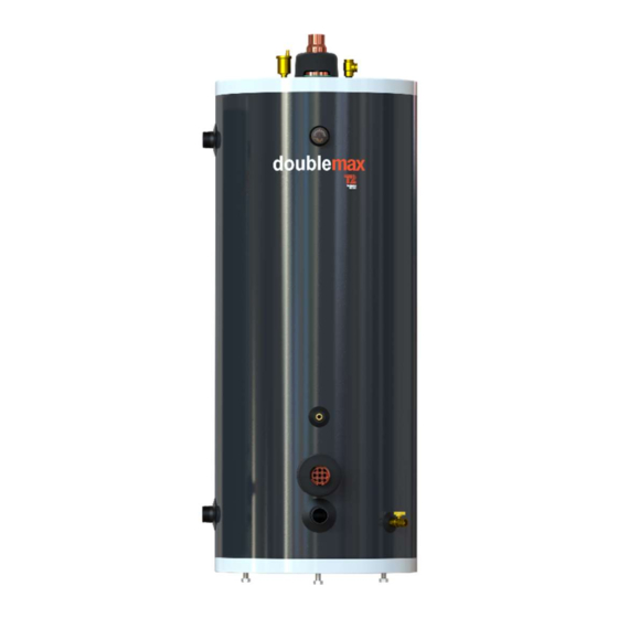
DoubleMax
Instantaneous indirect double-wall water heater
USE & CARE MANUAL
WITH INSTALLATION INSTRUCTIONS FOR THE CONTRACTOR
Your DoubleMax™ Instantaneous Indirect Double-Wall Water Heater has been carefully
assembled and factory tested to provide years of trouble-free service. In order to insure the
service intended, the following information is provided to enable proper installation, operation,
safety precautions and maintenance of this product.
It is imperative that all persons who are expected to install, operate or adjust this water heater
read the instructions carefully so that they may understand how to do so.
Any questions regarding the operation, maintenance, service or warranty of this water heater
should be directed to the entity from whom it was purchased.
When all installation steps have been completed, replace this installation manual in its original
envelope, and keep in a safe place for future reference.
THERMO 2000 Inc. reserves the right to modify at any time and without notice colors, components, materials, specifications or model
described in or shown in this document. DoubleMax™ is a trademark of Thermo 2000 Inc. Copyright © Thermo 2000 Inc. All rights
reserved.
THERMO 2000 INC.
TM
Revision: October 2023
Advertisement

Related Manuals for THERMO 2000 DoubleMax 120-9


Summary of Contents for THERMO 2000 DoubleMax 120-9
- Page 1 THERMO 2000 Inc. reserves the right to modify at any time and without notice colors, components, materials, specifications or model described in or shown in this document. DoubleMax™ is a trademark of Thermo 2000 Inc. Copyright © Thermo 2000 Inc. All rights reserved.
- Page 2 DoubleMax™ Use and Care Manual with Installation Instructions (October 2023) Page...
-
Page 3: General Safety Precautions
General Safety Precautions Be sure to read and understand the entire Use & Care Manual before attempting to install or operate this indirect water heater. Pay particular attention to the following General Safety Precautions. Failure to follow these warnings could cause property damage, bodily injury or death. Should you have any problems understanding the instructions in this manual, STOP, and get help from a qualified installer or technician. - Page 4 Introduction cause a boiler condensation condition. Too high WARNING an output rating may cause a boiler short cycling condition. In both cases, these conditions could The important safeguards and instructions affect the performance and life-time of the appearing in this manual are not meant to system.
- Page 5 LOCATION RESTAURANTS The water heater should be installed in a clean, If the water heater is to be installed in a restaurant dry location as close as practical to the boiler or or other location where the floor is frequently the heat source.
- Page 6 Check List of Mechanical Components for Proper Installation NON-PRIORITY SYSTEM PRIORITY SYSTEM A) If separate circulator for each zone A) If separate circulator for each zone 1 circulator per zone 1 circulator per zone 1 flow check per zone 1 flow check B) If only one circulator used by the B) If only one circulator used by the...
-
Page 7: Included Components
Included components The water heater will be shipped from the factory with the following components in a box: Ball valve 1/2 po Adjustable Aquastat ZMC200-BVP12NPT ZEL200-AQAJUSDM (separate box) Ball valve 3/4 po ZMC200-BVP34NPT 2 x Caps (Depends on model) ZFT380-CAP11/4 ZFT380-CAP11/2 Air vent ZFT380-CAP2... -
Page 8: Installation
Installation WARNING Use only clean copper or approved plastic pipe for water connections. Local codes or regulations The manufacturer’s warranty does not cover shall govern the exact type of material to be used. any damage or defect caused by installation attachment special To minimize heat loss during non-draw periods, a... - Page 9 Basic Piping Schematic Pump zoning Requirements: 1. The installation must conform to local, state, provincial and national codes. In any case where instructions conflict with the above, let those codes take precedence. 2. This is a basic piping schematic. It as to be adapted to your application. 3.
- Page 10 Basic Piping Schematic DoubleMax™ as a buffer tank – Additional connections Requirements: 1. The installation must conform to local, state, provincial and national codes. In any case where instructions conflict with the above, let those codes take precedence. 2. This is a basic piping schematic. It as to be adapted to your application. 3.
- Page 11 DOMESTIC HOT WATER TEMPERATURE & PRESSURE RELIEF VALVE BOILER WATER CONNECTIONS An automatic temperature & pressure relief valve This water heater may be connected individually, with a temperature probe of sufficient length must in multiples with others, or with an external be installed at the time of the installation.
- Page 12 corrosion that is associated with flue gas condensation. Use of additional connections Alternatively, when the boiler surfaces are hot The use of additional connections allows to use due to previous loads such as domestic hot water the DoubleMax™’s tank as a buffer tank to generation, the large temperature difference optimize runtimes and limits on/off cycling of the between the boiler and its return water can cause...
- Page 13 Velocities greater than 4 feet per second are often Pump flow rate = Boiler output TD 500 used on piping larger than 2 inches. Pump flow rate is express in U.S. gallons It is generally accepted that if proper air control is per minute or GPM.
- Page 14 Pressure loss from water flow in pipe fittings Piping system pressure drop calculation. and valves The pressure loss from friction in a closed piping In addition to the pressure loss in straight pipe, system is required to determine the required there will be pressure losses from turbulence and pump head.
- Page 15 PIPING SYSTEM PRESSURIZATION Pressure Vessel Code limits the maximum pressure on the boiler. Since it is a safety device, The objective of system pressure control is to limit it should not be considered an operating control. the pressure on all system equipment to its allowable working pressure, to maintain minimum Oxygen should be excluded from the system to pressure for all normal operating temperatures, to...
- Page 16 WIRING Wiring must conform to National Electrical Code and to state or local code requirements having jurisdiction. The water heater, when installed, must be electrically grounded in accordance with local codes, or, in the absence of local codes, with the National Electrical Code.
- Page 17 Circulator zoning wiring Zone valve zoning wiring Components must be wired to ensure that only Components must be wired to ensure that only the circulator for each zone is powered when the zone valve for a particular zone is powered demand for supply water occurs in that zone.
- Page 18 DoubleMax™ Use and Care Manual with Installation Instructions (October 2023) Page...
- Page 19 DoubleMax™ Use and Care Manual with Installation Instructions (October 2023) Page...
- Page 20 DoubleMax™ Use and Care Manual with Installation Instructions (October 2023) Page...
- Page 21 DoubleMax™ Use and Care Manual with Installation Instructions (October 2023) Page...
-
Page 22: Operation
Operation SAFETY PRECAUTIONS Leave all shutoff valves open. Return zone valve automatic operation. Before operating this water heater, be sure to read and follow these instructions, as well as Check system leaks repair. the warnings printed in this manual. Failure to do so can result in unsafe operation of the Purge air from the remaining zones, if necessary. - Page 23 connected fixtures. This provides constant water DANGER temperature under different working conditions. There is a Hot Water Scald Potential if the set When using models which are certified ASSE point is too high. 1017-1998 and, in addition, have successfully passed the cold water supply failure test (ASSE When this water heater is supplying general 1016-1996), loss of either hot or cold water to the purpose hot water requirements for use by...
-
Page 24: Maintenance
Maintenance Properly maintained, your water heater will Before manually operating the relief valve, provide years dependable, trouble-free make certain no one will be exposed to the service. It is recommended that a regular routine danger of coming in contact with hot water maintenance program established... -
Page 25: Troubleshooting System Problems
TROUBLESHOOTING SYSTEM PROBLEMS SYMPTOM POSSIBLE CAUSE ACTION Insufficient Install a pump or a valve-zoning panel with the domestic hot water domestic hot water priority feature. When System incapable of prioritizing boiler (boiler supplies demand occurs for domestic hot water, the water for domestic water use. -
Page 26: Replacement Parts List
Stop all domestic hot water requests. Wait until the double-wall tube reaches a temperature at which condensation will not occur. Dry the Heavy domestic hot water request is condensation and make a visual inspection. If going on causing condensation on the Water is dripping the there is still a leak, drain the domestic hot cold water input. - Page 27 Table 1: Friction Loss in Feet of Head Per 100 feet of Tube COPPER TUBE, TYPE "L" (nominal size in inches) Flow 1/2" 3/4" 1" 1-1/4" 1-1/2" 2" 2-1/2" 3" 4" Water U.S. 1.39 2.47 2.79 1.31 8.19 1.39 4.18 16.65 1.97 2.81...
- Page 28 Table 2: Friction Loss in Feet of Head Per 100 feet of Pipe SCHEDULE 40 STEEL PIPE (nominal size in inches) Flow 1/2" 3/4" 1" 1-1/4" 1-1/2" 2" 2-1/2" 3" 4" Water U.S. 1.06 1.39 2.11 4.77 1.20 1.21 3.17 9.98 1.81 2.50...
- Page 29 Table 3: Friction Losses Through Pipe Fittings & Valve Equivalent Feet of Straight Pipe for Fittings & Valves ( nominal size in inches) Fittings 1/2" 3/4" 1" 1-1/4" 1-1/2" 2" 2-1/2" 3" 4" 90° Elbow standard 1.6 ft 2.3 ft 2.7 ft 3.6 ft 4.5 ft...
- Page 30 Table 4: Friction Losses Through DoubleMax™ DoubleMax™ Use and Care Manual with Installation Instructions (October 2023) Page...
- Page 31 Spreadsheet 1: Pump sizing. System Flow Rate & Friction Losses Through DoubleMax™ piping circuit Step # 1 : Boiler Net Output Temperature Drop System Flow rate Flow rate thru TURBOMAX piping circuit BTU per hour US GPM °F Step # 2 : Flow rate Friction Loss in Feet...
- Page 32 Table 5: Water Content of DoubleMax™, Tubes, Pipes and Storage Tank DoubleMax™ Boiler Water Content Model Tank Volume DoubleMax™ 120-9 119 gallons US DoubleMax™ 80-5 80 gallons US DoubleMax™ 50-4 50 gallons US Water content of Copper tube and Steel pipe per 100 linear feet Pipe Copper tube Steel pipe...
- Page 33 Table 6: Expansion Tank Sizing 40 °F 40 °F 40 °F Lower system temperature 180 °F 200 °F 220 °F Higher system temperature Minimum operating pressure at tank 12. psig 15. psig 18. psig 30. psig 30. psig 30. psig Maximum operating pressure at tank Volume Volume of Diaphragm...
- Page 34 Table 7: Expansion Tank Sizing 50 °F 50 °F 50 °F Lower system temperature 180 °F 200 °F 220 °F Higher system temperature 12. psig 15. psig 18. psig Minimum operating pressure at tank 30. psig 30. psig 30. psig Maximum operating pressure at tank Volume Volume of Diaphragm...
- Page 35 Spreadsheet 2: Volume of Boiler Water in System & Expansion Tank Selection Pipe or Tube Volume in Pipe or Tube Boiler Water content Diameter Gallons per 100 feet Length (summation) Inches US Gallons Feet US Gallons Inches US Gallons Feet US Gallons ...
- Page 36 Thermo 2000 Inc. warranty to Installation in which the flow rate of liquid circulating in each coil exceeds 3 GPM US;...
Need help?
Do you have a question about the DoubleMax 120-9 and is the answer not in the manual?
Questions and answers