Advertisement
Quick Links
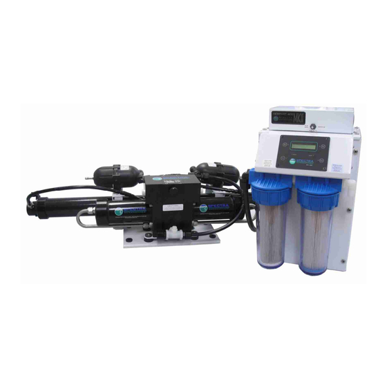
NEWPORT 400 Mk II
INSTALLATION & OWNER'S
MANUAL
Part 1..........Installation, Operation, Maintenance
Part 2....................... Programming and Controls
Spectra Watermakers, Inc.
20 Mariposa Road, San Rafael, CA 94901
Phone 415-526-2780 Fax 415-526-2787
www.spectrawatermakers.com
Feb 2012 mpc5000
1
Advertisement

Related Manuals for Spectra Watermakers NEWPORT 400 Mk II


Summary of Contents for Spectra Watermakers NEWPORT 400 Mk II
- Page 1 NEWPORT 400 Mk II INSTALLATION & OWNER’S MANUAL Part 1……..Installation, Operation, Maintenance Part 2………………….. Programming and Controls Spectra Watermakers, Inc. 20 Mariposa Road, San Rafael, CA 94901 Phone 415-526-2780 Fax 415-526-2787 www.spectrawatermakers.com Feb 2012 mpc5000...
- Page 3 Thank you for your purchase of a Spectra Newport system. Properly installed it will provide years of trouble free service. Please pay attention to the installation instructions and the sys- tem layout. Like any piece of mechanical equipment the system will require inspection and service from time to time.
- Page 4 Table of Contents Part 1 Page Number Installation Getting Started..............................5 Installation Basics.............................6 Component Placement............................7 Plumbing ................................10 Parker Tube Fitting Assembly Procedure ......................14 John Guest Super Speedfit ..........................15 Wiring................................16 MPC Tank Switch Wiring and operation .......................21 Membrane Pressure Vessel Relocation ......................39 Z Brane Installation ............................49 Operation New Systems Start Up and Testing........................23...
- Page 5 Getting Started Unpack the system and inspect it to make sure that it has not been damaged in shipment. Refer to the shipping list for your system to make sure you have received all of the compo- nents listed. Do not discard any packaging until you have found and identified all of the parts.
- Page 6 Installation Basics Thru-hull Not Supplied. Read the directions! Avoid tight hose bends and excessive runs. Use heavy gauge wire. Install feed pump as low as possible. Use a dedicated thru -hull with scoop type strainer. Flow Thru-hulls It is mandatory that a dedicated 3/4”...
- Page 7 Component Placement Refer to the Plumbing Diagrams Strainer Mount the strainer in an accessible area, close to the intake through - hull that can handle water spillage during service. Extra care during assembly must be taken to avoid air leaks from the strainer. Use the supplied “Quick Block”...
- Page 8 Clark Pump/Membrane Module Pressure Relief Valve The membrane maximum temperature specification is 120F. This module must be installed in an area that maintains a temperature below 120F (50C). A cool location is preferable. It may be placed as high in the boat as you desire. Make sure that the area around and under the pump does not have any water sensitive equipment.
- Page 9 Remote Control Panel The remote control panel can be mounted anywhere that is dry and convenient. Cut a 4 -9/16” (116 mm) wide by 2-7/8” (68mm) high opening for the panel. Locate in an area that is easily visible and easy to manipulate the but- tons.
- Page 10 System Piping schematic From the Clark pump brine dis- charge connector use the supplied 5/8 (15.9mm) clear braided vinyl hose to the brine overboard fitting. Mount the pressure gauge in the low pressure inlet gauge tee. Use the 1/2 inch nylon tubing between the feed pump module outlet and the Clark...
- Page 11 Note! When plumbing the Newport Pump Module route the feed water so that the front cover may be opened without removing the hose or tubing. Leave room on this side for attaching tubing and operat- ing the manual Feed water inlet from boost button on the diver- pump.
- Page 12 Product Water tubing Product water tubing is 1/4 “ (6.3mm) Parker tubing. See the Parker tube fitting assembly dia- gram on pg 14. Product water goes from the membrane into the pump module manifold where it passes through the flow meter, the salinity sensor and the diversion valve. If the salinity is good the diversion valve energizes and the product goes to the tank from the manifold product outlet.
- Page 13 Quick Disconnect Fitting Brine Discharge Route the Brine discharge from the quick disconnect fitting to a location above the waterline using the supplied 5/8” hose. Fresh Water Flush Run a feed line from the domestic cold pressure water system to the 1/2 hose barb on the fresh water flush assembly.
- Page 14 Parker Tube Fitting Assembly Procedure Spacer Single grab ring for 1/4" & 3/8" tube O-ring Use 2 grab rings for 1/2" tube Body Tubing Step 1: Dissemble fitting components 1/2" max Step 2: Install the Nut first then use the bevelled side of the Spacer to push the Grab Ring onto the tube no more than 1/2".
- Page 15 John Guest Super Speedfit...
- Page 16 DC Wiring Identify cables that are connected to the Newport Control System. Newport Mk II Systems have a Power Inlet harness with a terminal block, a 2 conductor boost pump cable, and a 50’ (15M) cable for the MPC -5000 display. A motor speed control sets the run speed and also slows the motor to the flush and service speeds.
- Page 17 Wiring (continued) Mount the main power terminal block in a junction box or on a bulkhead adjacent to the feed pump module. Make sure that this is a dry location well above bilge level and not subject to wa- ter spray. Route the control cable through the boat to the MPC display location.
- Page 18 WIRE SIZE CHART Newport Mk II DC System Wiring Wire Length FT. Meters AWG. SQ MM Mk II 12V 10.6 MkII 24V Meters AWG. SQ MM 10.6 Wire length is measured from source circuit breaker or fuse to control termi- nal block and back to the source again.
- Page 19 MPC Remote Control Display Panels There are currently two types of display options available: Liquid Crystal Diode (LCD) display, which is dark lettering on a backlit background, or Vacuum Florescent Display (VFD), which are bright characters on a dark background. The VFD display brightness can be adjusted using the Programming Function detailed in Part 2 of this manual.
- Page 20 Connection of Optional Accessories Use of any external devices not approved by the factory may cause permanent damage to the controller and is not covered by the Spectra warranty. Accessory outputs are lim- ited to 2 amps maximum load! Do not connect motors, pumps, etc to accessory outputs. Optional Z-brane System: Detailed instructions are included in the Z -Brane section.
- Page 21 Tank Switch Installation and Operation: There are two sets of terminals on the MPC -5000 PCB that can be used in four dif- ferent configurations to automatically start and stop the watermaker or to automatically stop the watermaker when the tank(s) are full without the auto start feature. These terminals are on the green ten pin connector and are labeled “Float Switch 1”...
- Page 23 New System Start-Up and Testing Use this procedure when starting a new watermaker for the first time and whenever the system contains preservative or cleaning compounds. Avoid running the system if the vessel is in contaminated water, such as in a dirty harbor or canal.
- Page 24 4. Press Auto Run Button The system will go into a start mode and the feed pump will start shortly after. The system should prime within 60-90 seconds. Check the strainer and the brine discharge for water flow. There should be no bubbles anywhere in the intake hoses and the feed pump should sound smooth after priming.
- Page 25 Service Prefilters and shut off the watermaker. Spectra watermakers MPC-5000 programming instructions can be found in section 2 of this manual. DO NOT ALTER THE FACTORY DEFAULT SETTINGS WITHOUT CONSULTING WITH A QUALIFIED TECHNICIAN FIRST!
- Page 26 Dry Testing With Artificial Ocean If it is not possible to test run the system with the boat in the water testing may be accomplished with an artificial ocean. Purchase enough salt to make 5 gallons (20 liters) of salt water. Salt water is 32,000ppm or 3% salt by weight.
- Page 27 Normal Start Up Using the Auto Run Button If the system contains preservative or cleaning chemicals follow the directions for New System Startup or Membrane damage will occur! Press the Auto Run button once and the system will prime and run for 1 hour. The display reads “AUTO RUN MODE”...
- Page 28 Flush Cycle Adjustment Before shipping from the factory the Newport watermaker flush cycle is set to factory default settings. Af- ter initial start up, and annually thereafter, the flush cycle should be checked. The water going overboard at the end of the flush cycle should not taste salty (<1000ppm). If the water at the end of the flush is still salty, or to minimize the use of fresh water during the flush cycle, follow these instructions to optimize the cycle.
- Page 29 Automatic Store Cycle Warning! Proper understanding of the Spectra flush system and the vessel’s fresh water sys- tem configuration is mandatory for extended Auto Store cycles. The flush cycles must not be allowed to drain all the fresh water from the vessel or damage to the vessel’s systems may oc- cur.
- Page 30 Manual Operation In the event of a component failure resulting in a shut down due to a false alarm, the failed component can be overridden using the Programming Function on the display. High Pressure, Service Prefilter, System Stalled (airlock), and Salinity Probe Failed can be defeated. The other safety shutdowns will still be activated.
- Page 31 Long Term Storage Procedures Watermakers are best run continuously. When not in use, biological growth in the membrane is the leading cause of membrane fouling. A warm environment will cause more growth than a cold environment. The auto fresh water flush system will greatly reduce biological growth but may not stop it completely in certain conditions.
- Page 32 Storage Procedure: Step 1: Flush the system twice. Push the “Auto Flush” button on the MPC -5000 display, when the first flush has been completed, press “Stop” to cancel the 5 day interval timer, then press “Auto Flush” again. ...
- Page 33 Storage & Winterizing Warning! Use only potable water antifreeze (Propylene Glycol). Do not use automotive antifreeze (Ethylene Glycol). Propylene Glycol is an effective biocide and antifreeze only at concentrations above 25%. Commercially available products range from 25 to 60 percent. They are usually labeled with a temperature rating.
- Page 34 Maintenance General Periodically inspect the entire system for leakage and chafe on the tubing and hoses. Repair any leaks you find as soon as practical. Some crystal formation around the Clark pump blocks is normal. Wipe down any salt encrusted areas with a damp cloth. The Seawater Strainer ...
- Page 35 If the membrane fails to respond to both cleanings, this is an indication of another problem with the system, or that it is time to replace the membrane. Contact Spectra Watermakers before removing a membrane. Membrane Cleaning For normal cleaning, the SC -3 Acid Cleaning Compound is used first, then the SC -2 Alkaline Cleaning Compound.
- Page 36 Note: Procedures are the same for the SC-2 and SC-3 cleaners Warning! The pressure relief valve on the Clark pump must be open for this procedure or membrane damage may result. Maximum pressure 50 psi. A Spectra Cleaning Compound (SC-2 or SC-3) must be mixed with fresh water at a ratio of 1 con- tainer of compound to 3 gallons (12L) of unchlorinated water to have the proper solution.
- Page 37 Salinity Cal window. Increase the calibration pa- rameter to increase the salinity reading. Conductivity calibration solutions are available from Spectra Watermakers if another method of calibration is necessary. These solutions are pre-made potassium chloride solutions with known salinity levels.
- Page 38 Additional filters, offshore cruising kit consisting of Clark pump seals, O-rings, tools and mem- brane cleaning chemicals. One replacement strainer screen, O -ring for strainer screen, O-rings for filter housing Part Number Spectra Watermakers parts list: SC-1 STORAGE CHEMICAL KIT-CHEM-SC1 SC-2 CLEANER...
- Page 39 Membrane Pressure Vessel Relocation Use ONLY Dayco Imperial Nylo-Seal 88-NSR-1/2 tubing for high pressure connections. Pay attention to the direction and flow path of the tubing before disassembly. Make sure that you reinstall the tubing in the same manner. Rotate the 90 degree high pressure tube fittings on the Clark pump for ideal tube runs.
- Page 40 Spectra High Pressure Tube Fitting Assembly Use ONLY Dayco Imperial Nylo -Seal 88-NSR-1/2 tubing for high pressure connections. Carefully fit and measure the tubing before cutting with a sharp razor knife or hose cutter and remove any burrs. Minimum tubing bend radius is 6”. Route tubing away from excessive heat sources and secure from vibration and chafe.
- Page 41 Spectra Watermakers Newport Troubleshooting Procedures SYMPTOMS PROBABLE CAUSE REMEDY Feed pump runs constantly, Manual override switches Turn off manual switch on will not turn off in “on” position control box Feed pump runs with loud - Intake blocked - Check thru-hull valve...
- Page 42 Spectra Watermakers Newport Troubleshooting Procedures Error Messages SYMPTOMS PROBABLE CAUSE REMEDY “System stalled” - pressure relief valve open - Close pressure relief valve - intake thru-hull closed - Check thru-hull (“system stalled” may alarm - air locked system - Check flow meter wiring at con-...
- Page 43 Operation and Repair Bulletins The following documents are sections of our complete service bulletin set. These are available on our website www.spectrawatermakers.com MEMBRANE CARE Membrane life is affected by a large number of factors and is somewhat unpredictable. A big commercial plant running 24/7 will get 10 to 12 years out of a set of membranes. But they do all kinds of fancy chemical injections and never shut the thing off.
- Page 44 MEMBRANE CLEANING WITH DETERGENT If the membrane has been fouled with oil it may be possible to save it by cleaning it with dish soap such as Joy. Don’t use anything that may contain bleach. You will need quite a lot of chlorine free fresh water.
- Page 45 PURGE MODE BYPASS Whenever the control power (12 or 24 volt DC) has been shut off the system will prompt you through the purge mode when it is turned back on. This is because the only time the MPC-5000 should be turned off is after the system has been pickled. Purge Mode prompts the operator to open the pressure relief and then runs seawater through the system for 20 minutes to clear away the chemicals.
- Page 46 BAD SMELLING PRODUCT WATER The reverse osmosis membrane is permeable by many gases including hydrogen sulfide, the gas that causes rotten eggs to smell the way they do. If there are bad odors in the feed water they will go through the membrane and the product water will be affected. Usually the source of the odor is from the decay of planktonic creatures trapped in the sea strainer and prefilters These tiny oxygen loving creatures soon suffocate and die inside the prefilter...
- Page 47 All Newport 400 Mk II Spectra Watermakers are equipped with a fresh water flush module. This module includes a charcoal filter to remove any chlorine in the fresh water that might damage the membrane.
- Page 48 CHARCOAL FILTERS The function of the charcoal filter element, p/n FT -FTC-CC, is to remove any chlorine in the fresh water flush water supply. It also removes any particulate matter. The charcoal filter we use removes 99.7% of the chlorine. Beware when buying other charcoal filters. If they don’t specify the percentage of chlorine removed, don’t use them.
- Page 49 Z-BRANE OPERATION MANUAL...
- Page 50 Z-Brane will not prevent freezing so that in cold climates Propylene Glycol is still required. ANODE INSTALLATION Spectra Watermakers ship the High Pressure Module with the White Z -brane electrodes(s) re- moved from their socket(s) to prevent shipping damage. Before the High Pressure Module is mounted the anodes should be installed.
- Page 51 WIRING The Z-Brane system is integral with the watermaker unit and only requires continuous 12Vor 24V DC power to be operative. Note: There is no reason to open the transformer enclosure. Do not service this unit without disconnecting the power source! There may be high voltage present.
- Page 52 Operation During normal operation the Red LED should be on . Power needs to be supplied to the Z - Brane unit at all times that you wish to have the bio -fouling protection. We recommend that your watermaker be flushed after each use not only to protect the membrane but to prevent corrosion in the feed water system.
- Page 54 End block B HP-TB-VEB-B1 Valve block HP-TB-VB End block A Composite cylinder HP-TB-VEB-A1 and base Brine out HP-CYL-CCA Pressure relief valve HP-TB-BV Center block HP-CB-CB10 Feed in Stainless steel tube HP-CYL-SST Cylinder ring HP-CYL-R Clark Pump Front View End Cap HP-CYL-EC End block A Valve block...
- Page 55 5/16"-3 1/4" SS AH Bolts HD-CPS-5/16X3 Relief Valve O-Ring SO-HPP-RV Annular Rings HP-TB-AR Spool Assembly KIT-HP-10VSA Relief Valve HP-TB-BV Annular Ring O-Rings Mount inside Valve Block SO-HPP-AR Valve Block 5/16"- 2 3/4" SS A.H. bolts HD-CPS-5/162.75 Reset button and O-ring End block B Piston O-ring SO-HPP-SP, PS20...
- Page 56 Valve port seals SO-HPP-VP Pilot valve port seals SO-HPP-PLP Piston rod HP-CYL-7/8R Center block cylinder O-rings SO-HPP-ECCB Pilot spool O-rings (4) Mount inside block SO-HPP-PV HP-CB-PVS Pilot spool HP-CB-PPS Pilot valve pin Pilot orifice SO-HPP-PS Pin seal O-rings HP-CB-PO HP-CB-PVPS Pin seals Center block HP-CB-PVCR...
- Page 57 1/2" SS tube S.S compression Piston with seal HP-CYL-SST fittings HP-CYL-PT PL-MTS-3/8X1/2S Composite cylinder and base HP-CYL-CCA SO-HPP-ECCB End cap O-ring Cylinder end cap HP-CYL-EC Cylinder Ring HP-CYL-R Cylinder Assembly...
- Page 58 10% CLARK PUMP PARTS LIST PART DESCRIPTION USAGE HP-CB-CB10 CENTER BLOCK HP-CB-INS CENTER BLOCK INSERT HP-TB-VB VALVE BODY HP-TB-BV BLEED VALVE HP-TB-VEB -A1 VALVE END BLOCK A 1 -1/4" HP-TB-VEB -A2 VALVE END BLOCK B 1 -1/4" HP-CB-PVPS PILOT VALVE PIN SEAL HP-CB-PPS PILOT VALVE PIN HP-CB-PVCR...
- Page 59 NEWPORT-400 MK II FT-STN-6 6" STRAINER (LARGE) PL-BSH-3/4X1/4N PL-VLV-3/4PVC 3/4" X 1/4" HEX BUSH- 3/4"NPT X 3/4"FPT 1 -WAY ING REDUCER NYL PVC VALVE FT-FHW-3PCS BLUE COLLAR FILTER HOUSING WRENCH PL-MFF -1/4X1/4 1/4"NPT X 1/4"FPT ELBOW FITTING NYL PL-NP-1/4N 1/4" NPT CLOSE NIPPLE PL-PRG-1/4P 1/4"...
- Page 60 NEWPORT-400 MK II PL-HP-1/2N 1/2" HEX PLUG NY- PL-TEE -1/2X1/2T PL-ACC-TK 1/2"NPT X 1/2" TUBE ACCUMULATOR TANK BRANCH TEE FM-PVB-PBE PLATE BRACKET END PL-HP-3/8 3/8" HEX PLUG NYLON KIT-HP10 HIGH PRESSURE PUMP 10% FOR N.P.ASSM PL-NLT-1/2HP PL-MTE -1/2X1/2P 1/2" HIGH PRESSURE TUBE 1/2"NPT X 1/2"TUBE FIT- (DAYCO) TING ELL.
- Page 61 NEWPORT-400 MK II PL-MFF -3/4X3/4 3/4"MPT X 3/4"FPT ELBOW FITT. PL-VLV-3W3/4 3/4" 3-WAY VALVE PL-HBE-3/4X3/4 3/4" NPT X 3/4" HOSE BARB ELL NYLON PL-HS-3/4VN 3/4" VINYL HOSE PL-CLP-10SS #10 HOSE CLAMP EL-FP-BPLDC824 300-1000 BOOSTER PUMP DC 8 -24V FM-NPC-SVBM NEWPORT II SERVICE & BOOST MODULE PL-FHB-3/4X3/4 3/4"FPT X 3/4 HOSE BARB ST.
- Page 62 NEWPORT-400 MK II EL-SWT-TG-DPDT EL-SWT-TSBHC TOGGLE SWITCH DP/DT TOGGLE SWITCH BOOT SEAL FM-MPC-MPCB MPC BOX EL-MPC-PCBDP MPC-5000 CIRCUIT BOARD PL-HS-3/4VN PL-HS-3/4SH 3/4" VINYL HOSE 3/4" REINFORCE SUCTION HOSE PL-HS-5/8VN 5/8" VINYL HOSE PL-NLT-1/2HP PL-HS-1/2VN 1/2" HIGH PRESSURE 1/2" VINYL HOSE TUBE (DAYCO)
Need help?
Do you have a question about the NEWPORT 400 Mk II and is the answer not in the manual?
Questions and answers