
Subscribe to Our Youtube Channel
Related Manuals for Thermal Arc FABRICATOR 252i


Summary of Contents for Thermal Arc FABRICATOR 252i
- Page 1 252i FabricatOr ® Multi prOcess welding inverter Operating Manual Revision: AC Issue Date: May 8, 2012 Manual No.: 0-5155 Operating Features:...
- Page 2 WE APPRECIATE YOUR BUSINESS! Congratulations on your new Thermal Arc product. We are proud to have you as our customer and will strive to provide you with the best service and reliability in the industry. This product is backed by our extensive warranty and world- wide service network.
- Page 3 While the information contained in this Manual represents the Manufacturer’s best judgment, the Manufacturer assumes no liability for its use. Operating Manual Number 0-5155 for: Thermal Arc Fabricator 252i Inverter Power Supply Part Number W1004400 Thermal Arc Fabricator 252i Inverter System...
-
Page 4: Table Of Contents
TABLE OF CONTENTS SECTION 1: SAFETY INSTRUCTIONS AND WARNINGS ............1-1 1.01 Arc Welding Hazards ..................1-1 1.02 General Safety Information for Victor CS Regulator .......... 1-5 1.03 Principal Safety Standards ................1-7 1.04 Symbol Chart ....................1-8 1.05 Precautions De Securite En Soudage A L’arc ..........1-9 1.06 Dangers relatifs au soudage à... - Page 5 Cleaning the Feed Rolls ................... 5-7 SECTION 6: KEY SPARE PARTS ................6-1 6.01 Tweco Spraymaster 250 MIG Gun ..............6-1 6.02 Fabricator 252 Power Supply Replacement Panels ........6-2 APPENDIX 1: OPTIONS AND ACCESSORIES ............A-1 APPENDIX 2: FABRICATOR 252i CIRCUIT DIAGRAM ..........A-2...
-
Page 7: Safety Instructions And Warnings
SAFETY INSTRUCTIONS FABRICATOR 252i SECTION 1: SAFETY INSTRUCTIONS AND WARNINGS WARNING PROTECT YOURSELF AND OTHERS FROM POSSIBLE SERIOUS INJURY OR DEATH. KEEP CHILDREN AWAY. PACEMAKER WEARERS KEEP AWAY UNTIL CONSULTING YOUR DOCTOR. DO NOT LOSE THESE INSTRUCTIONS. READ OPERATING/INSTRUCTION MANUAL BEFORE INSTALLING, OPERATING OR SERVICING THIS EQUIPMENT. -
Page 8: Safety Instructions
FABRICATOR 252i SAFETY INSTRUCTIONS 15. Keep all panels and covers securely in place. 3. Use protective screens or barriers to protect others from flash and glare; warn others not to watch the arc. 4. Wear protective clothing made from durable,... - Page 9 SAFETY INSTRUCTIONS FABRICATOR 252i 6. Be aware that welding on a ceiling, floor, bulkhead, 1. Keep your head out of the fumes. Do not breathe or partition can cause fire on the hidden side. the fumes. 7. Do not weld on closed containers such as tanks or 2.
- Page 10 FABRICATOR 252i SAFETY INSTRUCTIONS 7. Keep protective cap in place over valve except when 3. Have only qualified people remove guards or cylinder is in use or connected for use. covers for maintenance and troubleshooting as necessary. 8. Read and follow instructions on compressed gas cylinders, associated equipment, and CGA 4.
-
Page 11: General Safety Information For Victor Cs Regulator
SAFETY INSTRUCTIONS FABRICATOR 252i 1.02 General Safety Information for Victor CS Regulator LEAD WARNING Fire Prevention This product contains chemicals, includ- Welding and cutting operations use fire or combustion ing lead, or otherwise produces chemicals as a basic tool. The process is very useful when properly known to the State of California to cause controlled. - Page 12 FABRICATOR 252i SAFETY INSTRUCTIONS Ventilation Compressed Gas Cylinders The Department of Transportation (DOT) approves the design and manufacture of cylinders that contain gases WARNING used for welding or cutting operations. Ade quately ventilate welding, heating, and 1. Place the cylinder (Figure 1-1) where you will cutting work areas to prevent accumula- use it.
-
Page 13: Principal Safety Standards
SAFETY INSTRUCTIONS FABRICATOR 252i 1.03 Principal Safety Standards 4. NEVER use compressed gas cylinders without a pressure reducing regulator attached to the Safety in Welding and Cutting, ANSI Standard Z49.1, cylinder valve. from American Welding Society, 550 N.W. LeJeune Rd., 5. -
Page 14: Symbol Chart
FABRICATOR 252i SAFETY INSTRUCTIONS 1.04 Symbol Chart Note that only some of these symbols will appear on your model. Wire Feed Function Single Phase Wire Feed Towards Workpiece With Three Phase Output Voltage OFF. Three Phase Static Frequency Converter- Welding Gun... -
Page 15: Precautions De Securite En Soudage A L'arc
SAFETY INSTRUCTIONS FABRICATOR 252i 1.05 Precautions De Securite En Soudage A L’arc MISE EN GARDE LE SOUDAGE A L’ARC EST DANGEREUX PROTEGEZ-VOUS, AINSI QUE LES AUTRES, CONTRE LES BLESSURES GRAVES POSSIBLES OU LA MORT. NE LAISSEZ PAS LES ENFANTS S’APPROCHER, NI LES PORTEURS DE STIMULATEUR CARDIAQUE (A MOINS QU’ILS N’AIENT CONSULTE UN MEDECIN). - Page 16 FABRICATOR 252i SAFETY INSTRUCTIONS 9. N’enroulez pas de câbles électriques autour de votre corps. AVERTISSEMENT 10. N’utilisez qu’une bonne prise de masse pour la mise à la terre de la pièce à souder. LE RAYONNEMENT DE L’ARC PEUT BRÛLER LES YEUX ET LA PEAU; LE BRUIT PEUT 11.
- Page 17 SAFETY INSTRUCTIONS FABRICATOR 252i 2. Portez des lunettes de sécurité approuvées. Des écrans latéraux sont recommandés. AVERTISSEMENT 3. Entourez l’aire de soudage de rideaux ou de cloisons LE SOUDAGE PEUT CAUSER UN INCENDIE pour protéger les autres des coups d’arc ou de OU UNE EXPLOSION l’éblouissement;...
- Page 18 FABRICATOR 252i SAFETY INSTRUCTIONS 8. Lisez et respectez les consignes relatives aux bouteilles de gaz comprimé et aux équipements AVERTISSEMENT connexes, ainsi que la publication P-1 de la CGA, identifiée dans la liste de documents ci-dessous. LES ETINCELLES ET LES PROJECTIONS BRULANTES PEUVENT CAUSER DES BLES- SURES.
-
Page 19: Informations Générales De Sécurité
SAFETY INSTRUCTIONS FABRICATOR 252i 5. Utilisez la polarité correcte (+ et –) de l’accumulateur. AVERTISSEMENT DES PIECES EN MOUVEMENT PEUVENT AVERTISSEMENT CAUSER DES BLESSURES. LA VAPEUR ET LE LIQUIDE DE REFROID- Des pièces en mouvement, tels des ventila- ISSEMENT BRULANT SOUS PRESSION teurs, des rotors et des courroies peuvent PEUVENT BRULER LA PEAU ET LES YEUX. - Page 20 FABRICATOR 252i SAFETY INSTRUCTIONS 4. Gardez un extincteur approuvé du bon type et de D Protection Personnelle la bonne taille dans la zone de travail. Inspectez-le Les flammes de gaz produisent une radiation infrarouge régulièrement pour vous assurer qu’il est en état de qui peut avoir un effet néfaste sur la peau, et particu-...
-
Page 21: Principales Normes De Securite
SAFETY INSTRUCTIONS FABRICATOR 252i Mise en Garde AVERTISSEMENT Ouvrez la vanne de bouteille légèrement. Les bouteilles sont sous haute pression. Manip- Si vous l’ouvrez trop en grand, la bouteille ulez-les avec précautions. Des accidents sérieux pourrait se renverser. Quand vous ouvrez/ peuvent résulter d’une mauvaise manutention... -
Page 22: Graphique De Symbole
FABRICATOR 252i SAFETY INSTRUCTIONS 1.09 Graphique de Symbole Seulement certains de ces symboles apparaîtront sur votre modèle. Déroulement du Fil Sous Tension Mono Phasé Alimentation du Fil Vers la Pièce de Fabrication Hors Tension Trois Phasé Hors Tension Tri-Phase Statique... -
Page 23: Declaration Of Conformity
SAFETY INSTRUCTIONS FABRICATOR 252i 1.10 Declaration Of Conformity Manufacturer: Thermadyne Industries Address: 82 Benning Street West Lebanon, New Hampshire 03784 The equipment described in this manual conforms to all applicable aspects and regulations of the ‘Low Voltage Directive’ (European Council Directive 73/23/EEC as amended by Council Directive 93/68/EEC) and to the National legislation for the enforcement of this Directive. - Page 24 FABRICATOR 252i SAFETY INSTRUCTIONS This Page Intentionally Blank SAFETY INSTRUCTIONS AND WARNINGS 1-18 Manual 0-5155...
-
Page 25: Section 2: Introduction
Notes will be shown in italics. Additional copies of this manual may be purchased by contacting Thermal Arc at the address and phone number for your location listed in the inside back cover of this manual. Include the Owner’s Manual number and equip- ment identification numbers. -
Page 26: Symbol Chart
FABRICATOR 252i INTRODUCTION 2.04 Symbol Chart Note that only some of these symbols will appear on your model. Wire Feed Function Single Phase Wire Feed Towards Workpiece With Three Phase Output Voltage OFF. Three Phase Static Frequency Converter- Welding Gun... -
Page 27: Description
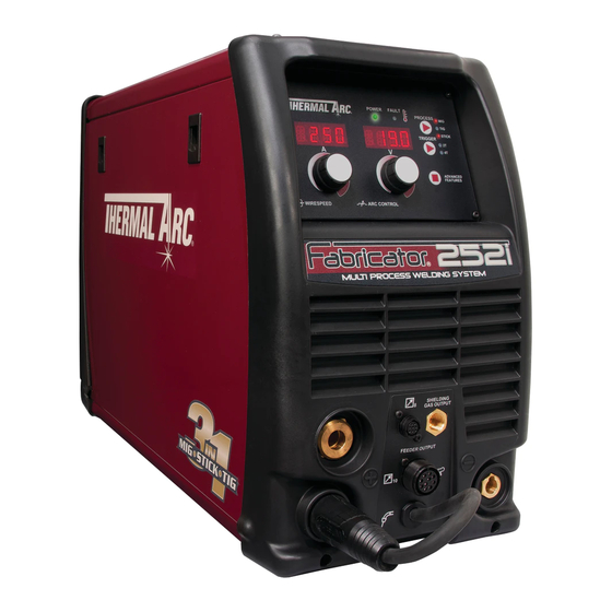
INTRODUCTION FABRICATOR 252i 2.07 Transportation Methods 2.05 Description The Thermal Arc Fabricator 252i is a self contained single phase multi process welding power source that is capable of performing MIG (GMAW/FCAW), STICK (SMAW) and WARNING Lift TIG (GTAW) welding processes. The Fabricator 252i is ELECTRIC SHOCK can kill. -
Page 28: Packaged Items
FABRICATOR 252i INTRODUCTION 2.08 Packaged Items Fabricator 252i Part No. (W1004401) - Fabricator 252i Power Supply - 15 ft Tweco® Spray Master 250 Amp MIG Gun - Contact tips (1 each) • .030" (0.8 mm) • .035" (0.9 mm) • .045" (1.2 mm) - Victor® Argon Regulator / Gauge & 10 ft. (3M) Hose -Tweco WeldSkill 200 Amp electrode holder with 13 ft. -
Page 29: Duty Cycle
6 minutes of the 10 minute period the Welding Power Source must idle and be allowed to cool. With Factory Fitted Supply Cord and Plug TIG (GTAW) MIG (GMAW) Safe Operating Region STICK (SMAW) Welding Current Max (amps) Art # A-10666 Figure 2-3: Fabricator 252i Duty Cycle with Upgraded Supply Lead and Plug Manual 0-5155 INTRODUCTION... -
Page 30: Specifications
250A @ 40%,20V 200A @ 60%, 18V 150A @ 100%, 16V Table 2-1: Fabricator 252i Specification NOTE Due to variations that can occur in manufactured products, claimed performance, voltages, ratings, all capacities, measurements, dimensions and weights quoted are approximate only. Achievable capacities and ratings in use and operation will depend upon correct installation, use, applications, maintenance and service. -
Page 31: Section 3: Installation Operation And Setup
A. In areas, free from moisture and dust. WARNING B. Ambient temperature between 32° F to 104° F. The Fabricator 252i must be electrically con- nected by a qualified electrical trades-person. C. In areas, free from oil, steam and corrosive gases. -
Page 32: Electromagnetic Compatibility
208-230/50A 40% @ 250A 40% @ 250A 40% @ 230A Table 3-1: Input Power Source Leads for Fabricator 252i WARNING ELECTRIC SHOCK can kill; SIGNIFICANT DC VOLTAGE is present after removal of input power. DO NOT TOUCH live electrical parts. - Page 33 INSTALLATION/SETUP FABRICATOR 252i 2. Maintenance of Welding Equipment B. Assessment of Area The welding equipment should be routinely maintained Before installing welding equipment, the user shall make according to the manufacturer’s recommendations. All an assessment of potential electromagnetic problems in access and service doors and covers should be closed the surrounding area.
-
Page 34: Power Source Controls, Indicators And Features
FABRICATOR 252i INSTALLATION/SETUP 3.06 Power Source Controls, Indicators and Features POWER FAULT ® LIFT TIG STICK ADVANCED Left Knob Right Knob FEATURES WIRESPEED ARC CONTROL Art # A-10503 Figure 3-1: Fabricator Control Panel Art # A-10504 Figure 3-2: Fabricator Front Connections WARNING DO NOT TOUCH the electrode wire while it is being fed through the system. - Page 35 INSTALLATION/SETUP FABRICATOR 252i 2. Fault Indicator 5. Advanced Features Button Advanced Features The yellow fault indicator will be illuminated when any of the faults are detected. ALL Faults will illuminate the indicator Press and release the Advanced Features button to enter 3.
- Page 36 FABRICATOR 252i INSTALLATION/SETUP 6. Left Knob: Amperage Control (Wirespeed) required output settings for a basic range of MIG welding applications. The value may also be adjusted while a weld is in progress – if this occurs, the left display will briefly...
- Page 37 INSTALLATION/SETUP FABRICATOR 252i 8. Left Digital Display 9. Right Digital Display MIG Mode MIG Mode This digital meter is used to display the pre-set (preview) This digital meter is used to display the pre-set (preview) Wirefeed Speed in Inches Per Minute (IPM) in MIG mode...
- Page 38 FABRICATOR 252i INSTALLATION/SETUP 11. Remote Control Socket The 8 pin Remote Control Socket is used to connect remote control devices to the welding power source. To make connections, align keyway, insert plug, and rotate threaded collar fully clockwise. Trigger Switch...
- Page 39 INSTALLATION/SETUP FABRICATOR 252i 12. 10 Pin Accessories Socket The 10 pin Accessories Socket is used to connect remote devices such as a spool gun to the welding power source. To make connections, align keyway, insert plug, and rotate threaded collar fully clockwise.
-
Page 40: Advanced Features Details
FABRICATOR 252i INSTALLATION/SETUP 14. Negative Welding Output Terminal Select the weld process (Control No 3) you wish to view Advanced Features for. The negative welding terminal is used to connect the welding output of the power source to the appropri-... - Page 41 INSTALLATION/SETUP FABRICATOR 252i Process STICK If the welder is in Advanced Features mode and the Weld Process Selection button (Control No 3) is pressed, the welder will exit Advanced Features mode, saving any change made, and change to the next weld process function in the sequence: MIG, LIFT TIG, STICK.
- Page 42 FABRICATOR 252i INSTALLATION/SETUP Right Display Function Left Display (Factory De- Limits Comments fault Values) LOCL = Local control of the Wirespeed MIG Operator and Voltage with the machines controls. MIG/CNTL LOCL LOCL - REMT Controls REMT = Remote control of the Wirespeed and Voltage with an accessory device.
- Page 43 INSTALLATION/SETUP FABRICATOR 252i Right Display Function Left Display (Factory De- Limits Comments fault Values) Provides Arc On Hours that the power source has Arc Hour Accu- welded. The number displayed is in hours and mulated Run- 0.0 – 9999.9 read only. It will rollover to 0 once 10,000 hours time have been reached.
- Page 44 FABRICATOR 252i INSTALLATION/SETUP "Right Display Function Left Display (Factory De- Limits Comments fault Values)" In “2T” (unlatched), the unit will enter down slope mode as soon as the trigger switch is released (ie if Down Slope is set to 5.0 S, the unit will ramp down from the present welding current to zero over 5 seconds).
-
Page 45: Attaching The Tweco Mig Gun
INSTALLATION/SETUP FABRICATOR 252i Right Display Function Left Display (Factory De- Limits Comments fault Values) Hot Start is used to improve the start character- Hot Start HOT/STRT OFF – ON istics for STICK electrodes, e.g. low hydrogen electrodes. Hot Start Time is the time that the Hot Start... -
Page 46: Installing A 12.5 Lb Spool (8" Diameter)
FABRICATOR 252i INSTALLATION/SETUP 4. If equipped, align the keyways of the MIG Gun Switch connector pigtail with the 8 pin receptacle to the right of the MIG Gun cable and plug them together. Secure by turning the locking ring to the right (clockwise ). Refer to Figure 3-8. -
Page 47: Installing A Standard Spool (12" Diameter)
INSTALLATION/SETUP FABRICATOR 252i 3.10 Installing a Standard Spool (12" diameter) As delivered from the factory, the unit is set for a 33 lb. or 12" spool. Installation of wire spool. Refer to Figure 3-10. 1. Remove Wire Spool Hub Retaining Clip. Grasp the loop and pull. -
Page 48: Inserting Wire Into The Feed Mechanism
FABRICATOR 252i INSTALLATION/SETUP 3.11 Inserting Wire into the Feed Mechanism WARNING ELECTRIC SHOCK CAN KILL! Make certain the input power is disconnected from the power source before proceeding. DO NOT reattach the input power until told to do so in these instructions. -
Page 49: Feed Roller Pressure Adjustment
INSTALLATION/SETUP FABRICATOR 252i 3.12 Feed Roller Pressure Adjustment NOTE Before attempting to set the drive roller pressure you must select GMAW mode on the front panel. See earlier in section 3 for information on how to select this feature. Once selected it will allow the activation of the drive roll when the trigger on the MIG Gun is activated. -
Page 50: Changing The Feed Roll
NOTE Installation of all styles of feed rolls for the Fabricator 252i are identical. WARNING The welding wire is electrically Hot if it is fed by depressing MIG Gun switch. Electrode contact to work piece will cause an arc with MIG Gun switch depressed. -
Page 51: Input And Output Wire Guide Installation
INSTALLATION/SETUP FABRICATOR 252i 3.15 Input And Output Wire Guide Installation NOTE .035" / .045" (0.9 / 1.2 mm) feed rolls and guides are installed from the factory. Other sizes need to be purchased separately. Input Wire Guide - Install (the shorter one) by loosening the input guide lockscrew and inserting the guide into the hole in the feedhead assembly. -
Page 52: Wire Reel Brake
FABRICATOR 252i INSTALLATION/SETUP 3.16 Wire Reel Brake The wire reel hub incorporates a friction brake which is adjusted during manufacture for optimum braking. If it is considered necessary, adjustment can be made by turning the tri-lobe nut inside the open end of the wire reel hub. - Page 53 INSTALLATION/SETUP FABRICATOR 252i SPECIFIC PROCEDURES for the use of regulators are listed below. 1. NEVER subject the regulator to inlet pressure greater than its rated inlet pressure. 2. NEVER pressurize a regulator that has loose or damaged parts or is in a questionable condition. NEVER loosen a connection or attempt to remove any part of a regulator until the gas pressure has been relieved.
- Page 54 FABRICATOR 252i INSTALLATION/SETUP Installation 1. Remove cylinder valve plastic dust seal. Clean the cylinder valve outlet of impurities that may clog orifices and damage seats before connecting the regulator. Crack the valve (open then close) momentarily, pointing the outlet away from people and sources of ignition.
-
Page 55: Set-Up Mig (Gmaw) Welding With Gas Shielded Mig Wire
3.18 Set-up MIG (GMAW) Welding with Gas Shielded MIG Wire The Fabricator 252i is supplied with a Tweco 250 AMP air-cooled MIG Gun. The Tweco MIG Gun is designed with an ergonomic handle and fewer parts to cause performance problems. The Tweco MIG Gun uses standard readily available Tweco consumable parts. - Page 56 FABRICATOR 252i INSTALLATION/SETUP When using a non shielded wire, you need to have an external gas source attached to the unit. For most Non Shielded Wire, connect the Work Lead to the negative - terminal and connect the MIG Gun polarity lead to the positive + terminal.
-
Page 57: Set-Up For Mig (Fcaw) Welding With Gasless Mig Wire
3.19 Set-up for MIG (FCAW) Welding with Gasless MIG Wire The Fabricator 252i is supplied with a Tweco 250 AMP air-cooled MIG Gun. The Tweco MIG Gun is designed with an ergonomic handle and fewer parts to cause performance problems. The Tweco MIG Gun uses standard readily avail- able Tweco consumable parts. -
Page 58: Set-Up For Lift Tig (Gtaw) Welding
FABRICATOR 252i INSTALLATION/SETUP 2. Check that the MIG wire size, contact tip, MIG Gun liner and drive roll groove are all the same size before fitting the MIG wire into the Power Source. 3. Connect the MIG Gun Polarity Lead to the negative welding terminal (-). If in doubt, consult the MIG electrode wire manufacturer. - Page 59 INSTALLATION/SETUP FABRICATOR 252i NOTE The following set up is known as Straight Polarity or DC Electrode Negative. This is commonly used for DC LIFT TIG welding on most materials such as steel and stainless steel. 1. Switch the ON/OFF Switch (located on the rear panel) to OFF.
-
Page 60: Set-Up For Stick Metal Arc Welding (Smaw)
FABRICATOR 252i INSTALLATION/SETUP 3.21 Set-up for STICK Metal Arc Welding (SMAW) WARNING Before any welding is to begin, be sure to wear all appropriate and recommended safety equipment. NOTE The following set up is known as DC Electrode Positive or reverse polarity. Please consult with the STICK electrode manufacturer for specific polarity recommendations. -
Page 61: Basic Welding Guide
BASIC WELDING FABRICATOR 252i SECTION 4: Shielding Gas Nozzle (Optional) (Optional) BASIC WELDING GUIDE Molten Metal Flux Cored Molten Electrode Slag Slag 4.01 MIG (GMAW/FCAW) Basic Welding Solidified Technique Base Metal Weld Metal Two different welding processes are covered in this sec-... - Page 62 FABRICATOR 252i BASIC WELDING Travel Speed 5° to 15° The speed at which the molten pool travels influences Longitudinal Angle the width of the weld and penetration of the welding run. MIG Welding (GMAW) Variables Direction of 90° Travel Most of the welding done by all processes is on carbon Transverse steel.
- Page 63 BASIC WELDING FABRICATOR 252i Establishing the Arc and Making Weld Beads Gas Nozzle Before attempting to weld on a finished piece of work, it Contact Tip (Tube) Tip to is recommended that practice welds be made on a sample Electrode Wire...
-
Page 64: Mig (Gmaw/Fcaw) Welding Troubleshooting
FABRICATOR 252i BASIC WELDING Electrode Wire Size Selection The choice of Electrode wire size and shielding gas used depends on the following: • Thickness of the metal to be welded • Type of joint • Capacity of the wire feed unit and Power Source • The amount of penetration required • The deposition rate required • The bead profile desired • The position of welding • Cost of the wire 4.02 MIG (GMAW/FCAW) Welding Troubleshooting... - Page 65 BASIC WELDING FABRICATOR 252i Problem 2 - Inconsistent Wire Feed WARNING Disengage the feed roll when testing for gas flow by ear. Wire feeding problems can be reduced by checking the following points. FAULT CAUSE 1 Feed roller driven by motor in the Wire spool brake is too tight.
- Page 66 B Low primary voltage B Contact supply authority. C Fault in power source C Have an Accredited Thermal Arc Service Provider test then replace the faulty component. 8 Arc does not have The MIG Gun has been Connect the MIG Gun to the positive (+) welding...
-
Page 67: Stick (Smaw) Basic Welding Technique
BASIC WELDING FABRICATOR 252i 4.03 STICK (SMAW) Basic Welding C. Cast Iron Technique Most types of cast iron, except white iron, are weld- able. White iron, because of its extreme brittleness, Size of Electrode generally cracks when attempts are made to weld it. - Page 68 FABRICATOR 252i BASIC WELDING Joint Preparations In many cases, it will be possible to weld steel sections without any special preparation. For heavier sections and for repair work on castings, etc., it will be necessary to cut or grind an angle between the pieces being joined...
- Page 69 BASIC WELDING FABRICATOR 252i Open Square Butt Single Vee Butt Joint Not less than 70° Joint 1/16” (1.6mm) max Gap varies from 1/16” (1.6mm) to 3/16” (4.8mm) depending on plate thickness 1/16” (1.6mm) Not less than Single Vee Butt Joint...
- Page 70 FABRICATOR 252i BASIC WELDING Striking the Arc If the travel is too fast, the bead will be narrow and strung out and may even be broken up into individual globules. Practice this on a piece of scrap plate before going on to If the travel is too slow, the weld metal piles up and the more exacting work.
- Page 71 BASIC WELDING FABRICATOR 252i Heavy plate will require several runs to complete the Art # A-07700_AB joint. After completing the first run, chip the slag out and clean the weld with a wire brush. It is important to do this to prevent slag being trapped by the second run.
- Page 72 FABRICATOR 252i BASIC WELDING Art # A-07702 Art # A-07704 Figure 4-28: Overhead Fillet Weld Figure 4-26: Multi Run Vertical Fillet Weld Distortion Distortion in some degree is present in all forms of welding. In many cases it is so small that it is barely...
- Page 73 BASIC WELDING FABRICATOR 252i weld is at a high temperature and hence rather soft, C. Restraint of Parts and, by expanding, pushes against the cooler, harder Forcible restraint of the components being welded is metal further away, and tends to bulge (or is "upset".
- Page 74 FABRICATOR 252i BASIC WELDING Art # A-07710_AB Block Sequence. The spaces between the welds are filled in when the welds are cool. Figure 4-34: Welding Sequence Art # A-07711_AB Figure 4-35: Step back Sequence Art # A-07428_AB Figure 4-36: Chain Intermittent Welding...
-
Page 75: Stick (Smaw) Welding Troubleshooting
ENi-Cl Suitable for joining all cast irons except white cast iron. Stainless Steel E318L-16 High corrosion resistances. Ideal for dairy work etc. Table 4-4: Thermal Arc Electrode Selection Chart 4.04 STICK (SMAW) Welding Troubleshooting FAULT CAUSE REMEDY 1 Welding current... - Page 76 FABRICATOR 252i BASIC WELDING 3 Non-metallic par- A Non-metallic particles may A If a bad undercut is present clean slag out and ticles are trapped be trapped in undercut cover with a run from a smaller gauge electrode. in the weld metal.
-
Page 77: Tig (Gtaw) Basic Welding Technique
BASIC WELDING FABRICATOR 252i 5 Portions of the A Small electrodes used on A Use larger electrodes and preheat the plate. weld run do not heavy cold plate. fuse to the surface B Welding current is too low. B Increase welding current. - Page 78 Easier Ceriated 2% steel, copper, alumi- starting, Wider current Grey num, magnesium and range, Narrower more their alloys concentrated arc. Table 4-9 NOTE The Fabricator 252i Inverter is not suited for AC TIG welding. BASIC WELDING 4-18 Manual 0-5155...
-
Page 79: Tig (Gtaw) Welding Problems
BASIC WELDING FABRICATOR 252i TIG Welding Filler Rods Base Metal DC Current DC Current Tungsten Filler Rod Argon Gas Joint Type Thickness for Mild for Stainless Electrode Diameter (if Flow Rate Steel Steel Diameter required) 0.040” 35-45 20-30 0.040” 1/16”... - Page 80 FABRICATOR 252i BASIC WELDING 6 Electrode melts or oxidizes A TIG Torch lead connect- A Connect TIG Torch lead to negative weld- when an arc is struck. ed to positive welding ing terminal. terminal. B No gas flowing to weld- B Check the gas lines for kinks or breaks ing region.
- Page 81 9 Arc start is not smooth. A Tungsten electrode is A Select the right size electrode. Refer to too large for the weld- Table 4-7 Thermal Arc Electrode Selection ing current. Chart. B The wrong electrode B Select the right electrode type. Refer to...
- Page 82 FABRICATOR 252i BASIC WELDING This Page Intentionally Blank BASIC WELDING 4-22 Manual 0-5155...
-
Page 83: Section 5: Power Source Problems And Routine Service Requirements
Power board indicates Over B. Ensure that air vents are not blocked/ temperature fault condition of obstructed power components C. Consult an Accredited Thermal Arc Service Provider. Input Power Fault Signal from Power board A. Check input power connections and cables... - Page 84 A. Welding may still be possible, but no weld Fault parameter NVROM. setting changes can be saved. B. Consult an Accredited Thermal Arc Service Provider. Unknown PCB Fault Welder control board cannot Consult an Accredited Thermal Arc Service identify an attached inverter Provider.
-
Page 85: Routine Service And Calibration Requirements
There are extremely dangerous voltage and power levels present inside this Inverter Power Source. Do NOT attempt to open or repair unless you are an accredited Thermal Arc Service Provider. Disconnect the Welding Power Source from the Mains Supply Voltage before disassembling. - Page 86 Note that due to the dangers of stray output currents damaging fixed wiring, the integrity of fixed wiring sup- plying Thermal Arc welding power sources should be inspected by a licensed electrical worker in accordance with the requirements below - 1.
- Page 87 PROBLEMS/SERVICE FABRICATOR 252i B. Calibration Requirements Where applicable, the tests outlined in Table 5-4 below shall be conducted by an accredited Thermal Arc service agent. Testing Requirements Output current (A) to be checked to ensure it falls within applicable Thermal Arc power source specifica-...
-
Page 88: Cleaning The Welding Power Source
6 Months Bring the unit to an authorized Thermal Arc Service Provider to remove any accumulated dirt and dust from the interior. This may need to be done more frequently under exceptionally dirty conditions. -
Page 89: Cleaning The Feed Rolls
PROBLEMS/SERVICE FABRICATOR 252i 5.04 Cleaning the Feed Rolls Clean the grooves in the drive rolls frequently. This can be done by using a small wire brush. Also wipe off, or clean the grooves on the upper feed roll. After cleaning, tighten the feed roll retaining knobs. - Page 90 FABRICATOR 252i PROBLEMS/SERVICE Notes PROBLEMS AND ROUTINE SERVICE Manual 0-5155...
-
Page 91: Section 6: Key Spare Parts
REPLACEMENT PARTS FABRICATOR 252i SECTION 6: KEY SPARE PARTS 6.01 Tweco Spraymaster 250 MIG Gun Art # A10554 Figure 6-1: Tweco Spraymaster 250 MIG Gun TWECO MIG TORCH PARTS ITEM PART NO. DESCRIPTION 20709S Tweco Spraymaster 250 Mig Gun 1620-1340... -
Page 92: Fabricator 252 I Power Supply Replacement Panels
FABRICATOR 252i REPLACEMENT PARTS 6.02 Fabricator 252 Power Supply Replacement Panels Art # A-10784 Figure 6-2 FABRICATOR 252i POWER SOURCE SPARE PARTS (Panels/Sheet Metal) ITEM PART NUMBER DESCRIPTION W7005323 Latch,Slide W7005366 Door, 252I W7005314 Panel,Rear,252I W7005367 Panel, Side, 252I W7005303... - Page 93 REPLACEMENT PARTS FABRICATOR 252i Art # 10332 Figure 6-3 FABRICATOR 252i POWER SOURCE SPARE PARTS (LEFT SIDE) ITEM PART NUMBER DESCRIPTION W7005311 Spool Hub Assembly W7005353 Wire Drive Assembly, 250i. (Does not include motor) 375838-002 Guide, Inlet 0.6-1.6mm See Appendix 1...
- Page 94 FABRICATOR 252i REPLACEMENT PARTS Art # A-10668 Figure 6-4: Right side and Front Replacement Parts FABRICATOR 252i POWER SOURCE SPARE PARTS (RIGHT SIDE AND FRONT) ITEM PART NUMBER DESCRIPTION W7005330 PCB, 252i Main Power W7005318 Circuit Breaker, 50A (On Off Switch)
-
Page 95: Appendix 1: Options And Accessories
Torch switch & remote current control with 8 pin plug Gas Hose,12.5ft,Male 5/8-18UNF W4013900 Roll Cage, 252i W4015101 Large HD Cart,Single Cylinder,211i-252i W4015001 Large HD Cart, Dual Cylinder, 211i-252i W4015002 Basic Utility Cart, Single Cylinder, 211i-252i W4014700 Adapter Cable for Miller® Spool Gun SG200M30AJC Table A-1: Options and Accessories... -
Page 96: Appendix 2: Fabricator 252I Circuit Diagram
FABRICATOR 252i APPENDIX APPENDIX 2: FABRICATOR 252i CIRCUIT DIAGRAM NOTE 1 LINE BREAKER FERRITE EMI BOARD LOAD FRONT PANEL VIDENT SOL+ POT_RETURN TRIG_SOL_RTN WFSPOT2 VBIAS TRIG2 MOTOR+ MOTOR- VPOT2 AUX TRIG VPOT1 WFSPOT1 POT_RETURN VBIAS TRIG_RETURN TRIG1 FRONT PANEL CONTROL BOARD... - Page 97 APPENDIX FABRICATOR 252i CHASSIS GND NOTE 1 BRIDGE + BRIDGE - COMMON MODE CHOKE BRIDGE / MOV BOARD GND PRI HI-POT TEMP SW HI-POT TRANSFORMER Art # A-10334 Revision Date Thermadyne World Headquarters PROTOTYPE 07/12/2011 16052 Swingley Ridge Road, Suite 300...
- Page 98 FABRICATOR 252i APPENDIX Notes APPENDIX Manual 0-5155...
-
Page 99: Statement Of Warranty
Statement of Warranty Effective 08/01/2011 This warranty supersedes all previous THERMADYNE® warranties. LIMITED WARRANTY: THERMADYNE® warrants that its products will be free of defects in workmanship or material. Should any failure to conform to this warranty appear within the time period applicable to the THERMADYNE®... - Page 100 Warranty SCHeDULe 5 Years Parts* / 3 Years Labor ArcMaster, Excelarc, Fabricator, Fabstar, PowerMaster Portafeed, Ultrafeed, Ultima 150, WC 100B * 5 years on the Original Main Power Transformer and Inductors not mounted on PCBoards. * 3 years on Power Supply Components 2 Years Parts and Labor Unless specified Auto-Darkening Welding Helmet (electronic Lens), ** 1 Month Harness Assy Victor Regulator for Fabricator 181i (No labor)
- Page 102 THE AMERICAS Denton, TX USA U.S. Customer Care Ph: 1-800-426-1888 (tollfree) Fax: 1-800-535-0557 (tollfree) International Customer Care Ph: 1-940-381-1212 Fax: 1-940-483-8178 Miami, FL USA Sales Office, Latin America Ph: 1-954-727-8371 Fax: 1-954-727-8376 Oakville, Ontario, Canada Canada Customer Care Ph: 1-905-827-4515 Fax: 1-800-588-1714 (tollfree) EUROPE Chorley, United Kingdom...
Need help?
Do you have a question about the FABRICATOR 252i and is the answer not in the manual?
Questions and answers