
Related Manuals for Vulcan Fitness 53040

Summary of Contents for Vulcan Fitness 53040
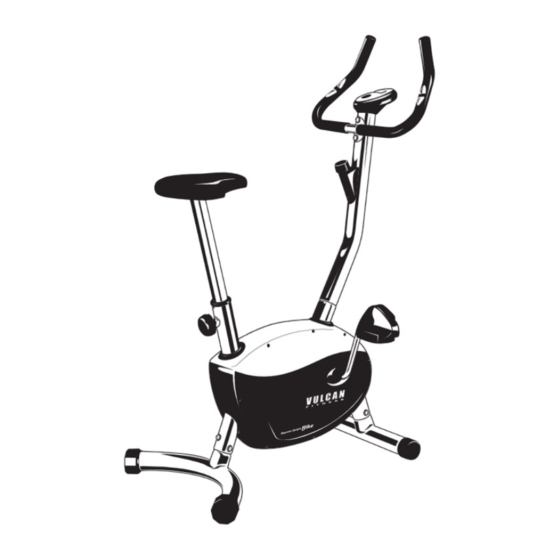
- Page 1 Bike Model No. 53040 *Artist expression, actual product may vary from illustration.
-
Page 2: Read This First
York Way, Daventry, Northants, NN11 4YB, England complete, no liability can be accepted for any errors or Tel: (01327) 701800 omissions. Vulcan Fitness reserves the right to change the Help desk Tel: (01327) 701824 specifications of the hardware and software described Fax: (01327) 706704 herein at any time without prior notice. -
Page 3: Safety Precautions
READ THIS FIRST Safety Precautions WAR N I N G Before using the equipment, please ensure that you read Your product is intended for use in clean dry the safety precautions described below. Always ensure that conditions. You should avoid storage in excessively the equipment is operated correctly. -
Page 4: Table Of Contents
Table of contents Read This First .............. 02 - 03 purchasing a • Disclaimer/Customer Support ........02 • Safety Precautions ............03 VULCAN FITNESS Table Of Contents ............... 04 equipment. Introduction ................05 Assembly Instructions ..........06 - 08 You have chosen a high quality, safe and innovative piece •... -
Page 5: Introduction
INTRODUCTION • Magnetic tension upright cycle • Adjustable saddle in height • Smooth, quiet, durable, compact and comfort • Extra large LCD • 5KG cast iron flywheel, belt drive • Magnetic system with dial tension knob • Heavy duty one piece crank system Vulcan Magnetic Upright Bike | INSTRUCTION MANUAL •... -
Page 6: Assembly Instructions
ASSEMBLY INSTRUCTIONS Getting Started Place all parts from the box in a cleared area and position Part No. 19 x 1 them on the floor in front of you. Remove all packing ROUND KNOB (Ø60 X 88MM X M10 X Ø8) materials from your area and place them back into the box. -
Page 7: Assembly Instructions
ASSEMBLY INSTRUCTIONS Step 1 Step 2 Attach the Front Stabilizer (4) to the tube of the Main Attach the Rear Stabilizer (16) to the tube of the Main Frame (1) with three M8 x 16 Bolts (41) and ø8 Curve Frame (1) with four M8 x 16MM Bolts (41) and ø8 Curve Washer (46). -
Page 8: Assembly Instructions
ASSEMBLY INSTRUCTIONS Step 4 A. Insert the Hand Pulse Wires (62) into the hole on the Handlebar Support (27) and then pull them out of the top end of the Handlebar Support (27). Attach the Handlebar (25) onto the Handlebar Support (27) with two M8 x 16 Bolts and ø8 Curve Washers (46). -
Page 9: Operational Instructions
OPERATIONAL INSTRUCTIONS Operating Instructions: Adjusting the tension control knob: To increase the load, turn the tension control knob in a clockwise direction. To decrease the load, turn the tension control knob in a counterclockwise direction. Adjusting the rear stabilizer end cap: Turn the rear stabilizer end cap on the rear stabilizer as needed to level the bike. -
Page 10: Troubleshooting
TROUBLESHOOTING Troubleshooting Guide: • Verify that all bolts and nuts are locked properly and the turning parts are free of damage and should be able to turn freely. • Clean the equipment with soap and a slightly damp cloth only. Please do not use any solvents to clean the equipment. PROBLEM POTENTIAL CAUSES CORRECTIONS... -
Page 11: Fitness Guide
FITNESS GUIDE Conditioning Guidelines: How you begin your exercise program depends on your physical condition. If you have been inactive for several years or are out of shape, start slowly and increase your workout gradually. Increase your workout intensity gradually by monitoring your heart rate while you exercise. -
Page 12: Warranty
This warranty does not extend to any product that has been damaged or rendered defective: (a) as a result of accident, misuse, abuse or lack of reasonable care; (b) by the use of parts not manufactured by Vulcan Fitness or sold by Vulcan Fitness;... - Page 13 Vulcan Magnetic Upright Bike | INSTRUCTION MANUAL • 13...
-
Page 14: Part List
PART LIST 14 • Vulcan Magnetic Upright Bike | INSTRUCTION MANUAL... - Page 15 PART LIST KEY NO. DESCRIPTION KEY NO. DESCRIPTION MAIN FRAME (534 X 116 X 424) BRACKET (35 X 18 X 14 X 2) FRONT STABILIZER END CAP (Ø66 X 40) FLYWHEEL AXIS (Ø10 X 140) REAR STABILIZER END CAP (Ø50) SPACE (Ø13 X Ø10.5 X 20) FRONT STABILIZER (Ø50 X 1.5 X 400) PRESSING BELT WHEEL...
- Page 16 © 2008 VULCAN FITNESS...
Need help?
Do you have a question about the 53040 and is the answer not in the manual?
Questions and answers